Drill String Failures and Prevention
1/20
There's no tags or description
Looks like no tags are added yet.
Name | Mastery | Learn | Test | Matching | Spaced | Call with Kai |
|---|
No analytics yet
Send a link to your students to track their progress
21 Terms
Types of Drill Stem Failure
❑ When a component cannot perform its function
❑ Complete separation of two members of DS (parting)
❑ Leak (washout)
Location of failures
Tube body
Tool Joint
Threads
On any drill stem component
Group 1 - Failure Mechanism
Mechanisms of failure that can be stopped:
❑ Tension
❑ Torsion
❑ Combination of Tension and Torsion
❑ Collapse Pressure
❑ Burst Pressure
Tensile Failures
When tensile loads > capacity of the weakest component in the drill stem (drill pipe)
When connection was made up beyond recommended torque
When tensile loads > ultimate tensile strength
Surface of break at 45 degrees to axis of pipe
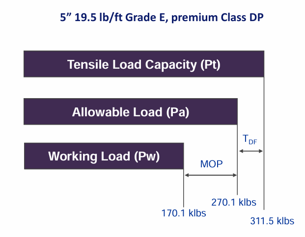
Mitigation method for tensile failures
Select DP that is capable of carrying the anticipated loads plus a Margin of Over-pull plus a design factor.
Use a marking system that shows tube weight and grade.
Make sure that the rig weight indicator is calibrated properly and does not exceed the allowable tensile load.
Torsional Failures
Occur in form of stretched pin or belled box
Occur in the tool joint
Mitigation method for torsional failures
Select tool joint ID and OD so that the maximum makeup torque exceeds the maximum anticipated torsion.
Check tool joints to ensure that they meet with all the dimensional requirements.
Make sure torque application device is working and calibrated properly.
Use API tool joint compound with a FF between 0.95 and 1.05 or compensate the applied torque accordingly.
Make up connections to recommended torque.
Combination of Tension and Torsion Failures
Occur while fishing or pulling on stuck pipe
Burst and Collapse Failures
If pressure loading exceeds capacity
Burst - happen high in the hole
Collapse - happen deep in the hole when pipe is evacuated for drill stem testing
Group 2 - Failure Mechanisms
Mechanisms of failure that cannot be stopped but can be controlled:
❑ Fatigue
❑ Split Box
❑ Sulfide Stress Cracking
❑ Stress Corrosion Cracking
Fatigue Failures
When cyclic stress with the peak stress higher than 40% UTS (ultimate tensile strength)
When stress concentrators raise the peak stress locally
Corrosive environment
Fracture toughness
Sources of Cyclic Loads in Fatigue Failures
Rotating pipe in a dog leg
One side in tension, one in compression
Addition and subtraction of forces create cyclic loading
Rotating BHA through a hole diameter change
Stabilizer stick/slip
Rotating pipe in a washout
Bit whirl
Bit bounce
Prevention method for fatigue failures
Early detection of Vibrations & Washouts
Starting with good materials and component design
Reducing cyclic stresses and stress concentrations
Plan the trajectory with the lowest dogleg severity
Avoid practices that create unplanned doglegs, specially in vertical holes.
Invest in straightening trips to lower Dogleg severity.
Stabilize the BHA, especially if hole enlargement around the BHA is a problem.
Keep the Neutral point below the top of the BHA.
Keep drill-pipe compression less than critical buckling load in high angle wells
Monitor vibration. Optimize BHA configurations, WOB, RPM.
Consider rotating the string more slowly, by means of introducing a mud motor to the BHA, only if hole cleaning and directional objectives allow.
Reducing the corrosiveness of the environment
Ensuring good rig site operating practices
Following an inspection program
Corrosion Failures
Reduction in the wall thickness of tubulars
Occurs due to electrochemical reactions with corrosive agents
Pitting - a highly localized metal loss which penetrates the wall of the tubular
3 patterns of corrosion:
Uniform wall thickness reduction
Localized patterns of metal loss
Pitting - leads to eventual failure
Factors affecting corrosion rate
Higher temperature
Higher flow rate, especially if abrasive solids present
Higher concentration of corrosive agents (O2, H2S and CO2)
Prevention method for corrosion
Oxygen
pH
CO2 and Chlorides
H2S (Reduce or prevent H2S)
exposure of high tensile steels to partial pressure H2S > 0.05 psi can lead to catastrophic failure
metal becomes brittle and will break suddenly without warning
Inhibitors
Sulfide Stress Cracking

Prevention method for sulfide stress cracking failures
Keep H2S out of the mud system
drilling overbalanced
keeping pH high
using H2S scavengers
using OBM
Control the metallurgy
use different grade pipe
Drill String Failure Prevention - ADIOS
A - Attributes: These are the metallurgical properties and dimensions that are built into each drill string component at manufacturing. E.g.: strength, toughness
D - Design: Drill stem design is selecting components and configuring assemblies to accomplish the drilling objective (to provide a drill string that will carry the loads and resist failure)
I - Inspection: Drill Stem components, unless new, have been exposed to handling damage and an unknown amount of cumulative fatigue damage.
O - Operation: The Drilling operation presents many opportunities to overload and misuse the drill stem.
S - Surroundings: The chemical and mechanical environment surrounding the drill stem can have major effect on failure probability.
Symptoms of Poor Drilling Performances

Optimization to mitigate overload and fatigue failures
Improve hydraulics
efficient cooling and lubrication of drill bit and BHA
reduces friction and heat buildup (prevent material degradation and fatigue)
enhance cutting removal (reduce stress on DS)
Reduce side loads
by optimizing well trajectory and using stabilizers (to reduce bending stress and wear)
Reduce curvature index (dogleg severity)
smoother wellbore path (reduce bending loads)
Reduce stability index
by proper bha design and weight distribution (avoid vibrations and improve stability)
Reduce torque and drag
TD leads to twisting failures
by using proper lubricants, centralizers and wellbore conditioning (to reduce mechanical resistance)
Improve hole cleaning
poor HC leads to cuttings buildups
by efficient mud programs and optimal annular velocity (to prevent excessive loads on the DS)