Ch 4 - Logical Database Design and the Relational Model
1/64
There's no tags or description
Looks like no tags are added yet.
Name | Mastery | Learn | Test | Matching | Spaced | Call with Kai |
|---|
No analytics yet
Send a link to your students to track their progress
65 Terms
Determinant
The attribute on the left-hand side of the arrow is a functional dependency. Its value determines the value of other attributes
Functional dependency
A constraint between two attributes or two sets of attributes in which the value of one attribute is determined by (in practice, known based on) the value of another attribute.
The value of one attribute (the determinat) determines the values of another attribute
Transitive dependency.
A functional dependency between two (or more) non key attributes
Recursive foreign key.
A foreign key in a relation that references the primary key values of that same relation
Normalization.
The process of decomposing relations with anomalies to produce smaller, well-structured relations
Composite key.
A primary key that consists of more than one attribute
Candidate key.
An attribute, or combination of attributes, that uniquely identifies a row in a relation/table
Each non-key field is a functionally dependent on every candiate key
Normal form
A state of a relation that results from applying simple rules regarding functional dependencies (or relationships between attributes) to that relation
Partial functional dependency.
A functional dependency in which one or more non-key attributes (such as Name) are functionally dependent on part (but not all) of the primary key
Enterprise key.
A primary key whose value is unique across all relations
Surrogate primary key
A serial number or other system assigned non-intelligent primary key for a relation
Composite key
A key made up of more than one column
Secondary key
One or a combination of fields for which more than one record may have the same combination of values
Data type.
Each unit of a detailed coding scheme recognized by system software, such as a DBMS (database management system), for representing organizational data
erd vs eerd vs transform ERD vs Normalization (Print out notes)
ER Model
A conceptual schema to depict a database
ER diagram (ERD)
Visual representation in a database
EERD
Builds upon ERD by including more complex concepts like generalization, specialization and aggregation
Normalization
Aims to organize data structures to reduce redundancy
1NF removes repated group, 2NF lessons redundancy, 3NF reduces data duplications
Important properties of tables/relations
Each relation in a database has a unique name.
An entry at the intersection of a row and a column must be atomic (meaning it can not be further divided) and a single value.
Each row must be unique.
Each attribute/column within a table must have a unique name.
The sequence (order) of the attributes is not significant (i.e. attributes can be in any order).
The sequence of rows in a table is not significant.
Data structure
Tables (relations), rows, columns
Data manipulation
Powerful SQL operations for retrieving and modifying data
Data Integrity
Mechanisms for implementing business rules that maintain integrity of manipulated data
Relation
•A relation is a named, two-dimensional table of data.
•Consists of rows (records) and columns (attribute or field)
Note: All relations are in 1st Normal form
Requirements for a table to qualify as a relation:
–It must have a unique name.
–Every attribute value must be atomic (not multivalued, not composite).
–Every row must be unique (can’t have two rows with exactly the same values for all their fields).
–Attributes (columns) in tables must have unique names.
–The order of the columns must be irrelevant.
–The order of the rows must be irrelevant.
Relation vs Relationship
Relation
A table that follows certain rules and refers to actual relational database architecture
Relationship
A conceptual term hat refers to how entities relate to each other
The E-R concept of relationship will be implemented by primary and foreign keys connecting the database’s relations
Correspondence w/ E-R Model
Relations (tables) = entity types and many to many relationship types
Rows = entity instances and with many-to-many relationship instances
Columns = attributes
The word relation (in relational database) is not the same as the word relationship (E-R model)
Keys
Keys are to databases as identifiers are to E-R models
Can be simple or composite
Primary keys
Unique identifiers of the relation
Examples:
Employee numbers, social security, numbers, etc
This guarantees that all rows are unique
Foreign keys
Identifiers that enable a dependent relation (on the many side of a relationship) to refer to its parent relation (on the one side of the relationship)
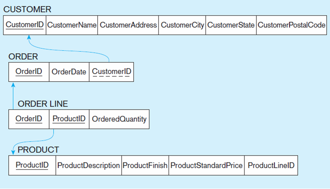
EER Notation
Solid Underlines = Primary Key
Dashed underlines = Foreign Key
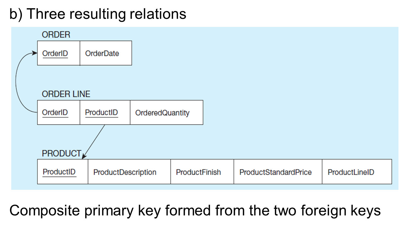
Composite Primary Key = Order Line (Order ID and Product ID) which are foreign keys to the other relations (Order and Product)
Foreign and Primary Key for 1:N Relations
The relation on the many side of the 1:N relationship will have a foreign key that corresponds with the primary key of the relation on the one side
Foreign and Primary key for M:N relationship between
Must implement a separate relation, often called an “intersection table” or a “junction table”
Domain Contraints
Allowable values for an attribute (includers data types and restrictions on values)
Entity Integrity
No primary key attribute may be null. All primary key fields MUST contain data values
Referential Integrity
Rules that maintain consistency between the rows of two related tables
Foreign key value (on relation of the many side) MUST match a primary key value in the relation of the one side (or the foreign key can be null)
For example: Delete Rules
Specify how such deletions can be controlled within the database
Restrict, Cascade, Set-To-Nul
Delete Rules: Restrict
Don’t allow delete of “parent” side if related rows exist in “dependent side”
Delete Rules: Cascade
Automatically delete “dependent” side rows that correspond with the “parent” side row to be deleted"
Delete Rules: Set-to-Null
Set the foreign key in the dependent side to null if deleting from the parent side→ not allowed for weak entities
Referential Integrity (EXAMPLE)
Referential integrity constraints are drawn via arrows from dependent to parent table
Rules for designing relational databases based on E-R and EER data models
Steps
1) Construct E-R or EER model
2) Create logical mode (relational database design)
Rules
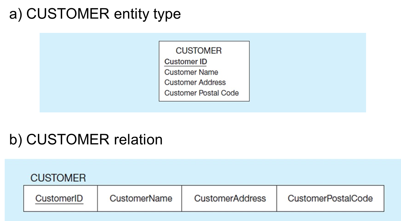
Simple attributes: E-R attributes map directly onto the relation
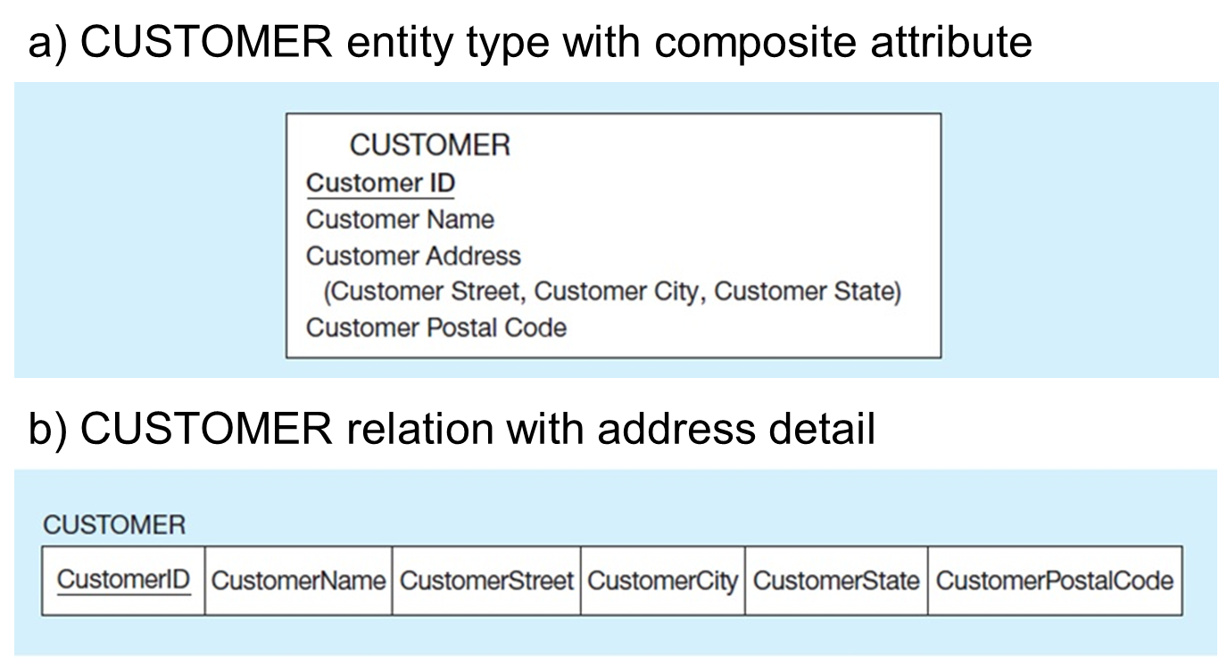
Composite attributes; Use only their simple, component attributes
Multivalued attributes: Become a separate relation with a foreign key taken from the superior entity
Mapping Simple Attributes
Mapping Composite Attribute
Mapping a Multivalued Attribute
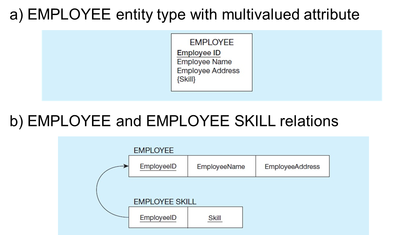
Multivalued ex: {skill} must be converted to separate relations in the logical database design
no such thing as multivalued attribute in relational databases
There is a one-to-many relationship in the final database structure. The employee skill relation has a composite primary key (Employee ID and Skill). The EmployeedID portion of this composite primary key is also a foreign key to the Employee table (many side)
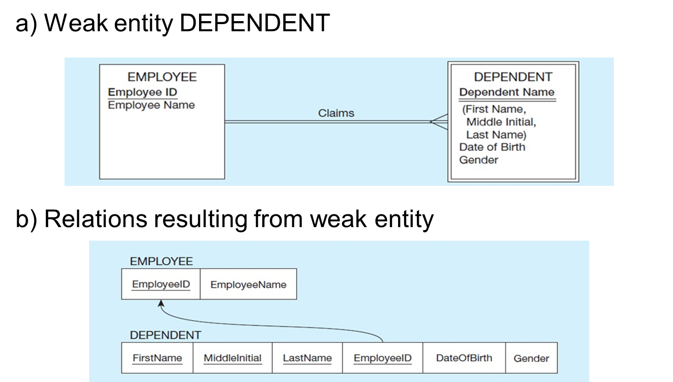
Mapping Weak Entities
Become separate relation (table) with a foreign key taken from the superior entity
Primary key composed of:
Partial identifier of weak entity
Primary key of identifying relation (strong entity)
Weak entity cannot exist without its corresponding strong entity. So, the domain constraint for the foreign key should NOT allow null value if DEPENDENT is a weak entity
Mapping Binary Relationships
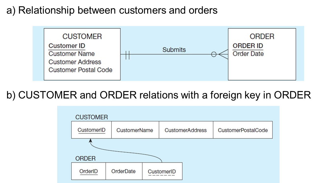
One-To-Many
Primary key on the one side become a foreign key on the many side
Many to many
Create a new relation with the primary keys of the two entities as its primary key
One-to-one
Primary key on mandatory side becomes a foreign key on optional side
Mapping 1:N Relationship (EXAMPLE)
Identifying the functional depenedies (which value gets it value from another attribute)
Which attribute could be used to uniquely identify the value of another attribute
Mapping an M:N Relationship
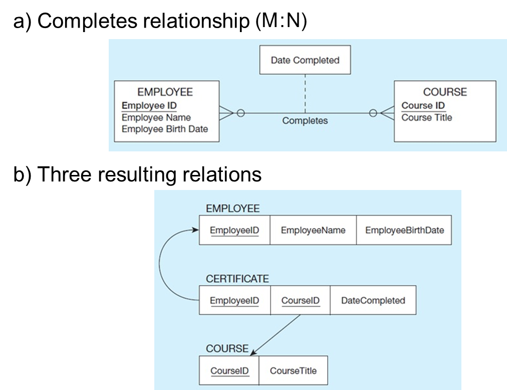
Must create separate relation (table) often called intersection table or junction table
new table’s primary key is a composite (employee ID and course ID)
Mapping a Binary 1:1 Relationship
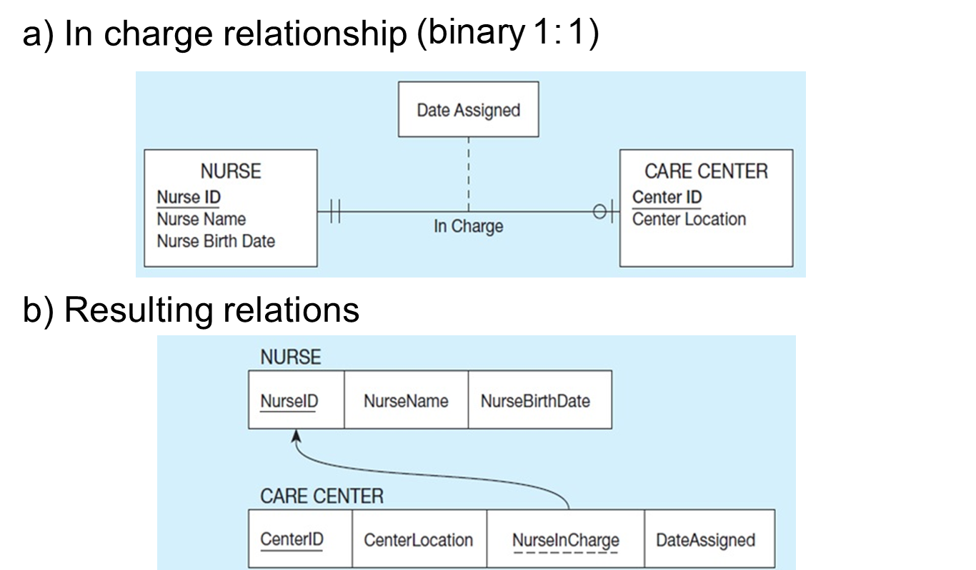
Foreign key in this relationship is NurseInCharge and goes into Care Center
Because of the mandatory one in the relationship, this must mean that the NurseInCharge field can never have a null value
Mapping Associative Entities
Identifier Not Assigned
Default primary key for the association relation is composed of the primary keys of the two entities (as in M:N relationship)
Identifier Assigned
It is natural and familiar to end users
Default identifier may not be unique
Mapping an Associative entity with an Identifier
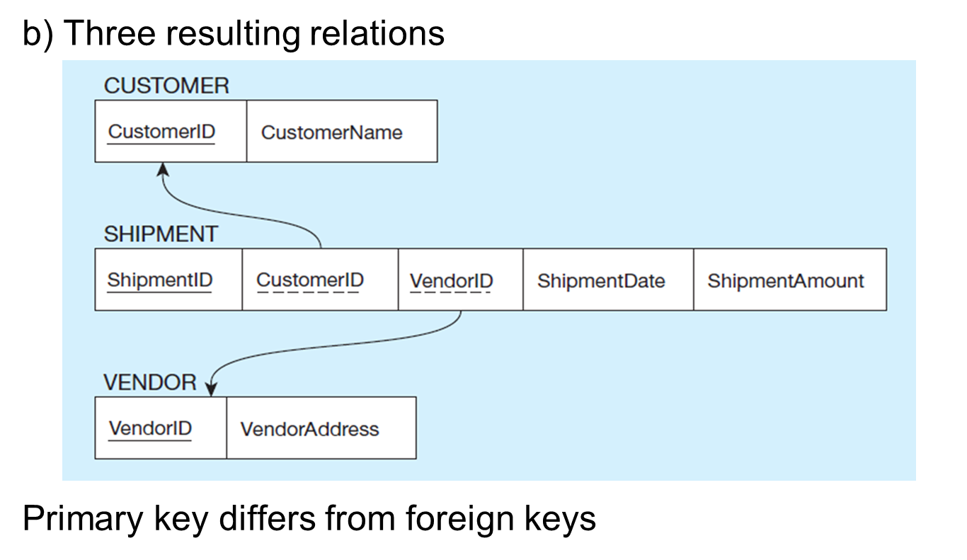
The resulting intersection relation are not part of the primary key
So it is possible to have multiple shipments from the same vendor to the same customer
Mapping Unary Relationships
One to many
Recursive foreign key in the same relation
Many-to-Many
One for the entity type
One for an associative relation in which the primary key has two attributes, both taken from the primary key of the entity
Example of Mapping a Unary 1:N Relationship
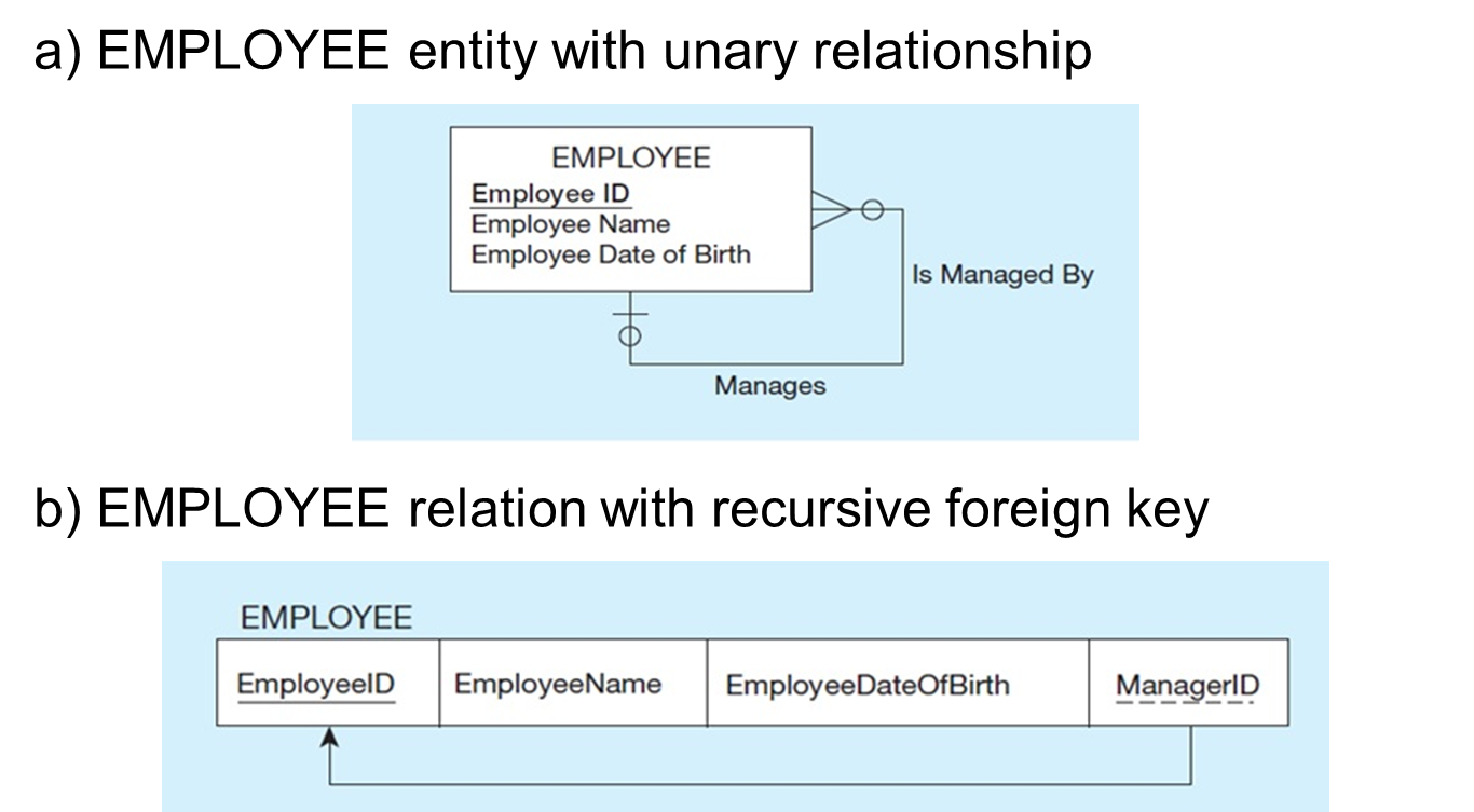
The E-R diagram involves a one-to-many relationship. Thus, the foreign key is in the same table as the primary key. “recursive key”
Optional relationship means not every employee has a supervisor. ManagerID field could be null
This structure is an example of storing hierarchies. Enables the representation of a supervisor who has subordinates, and these subordinates could in turn manage other subordinates, etc
Example of Mapping a Unary M:N Relationship
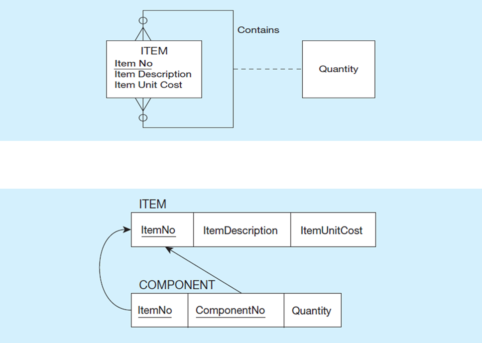
Many to many always requires a separate table (relation)
Mapping Ternary (and n-ary) Relationships
One relation for each entity and one for the associative entity
Associative entity has foreign keys to each entity in the relationship
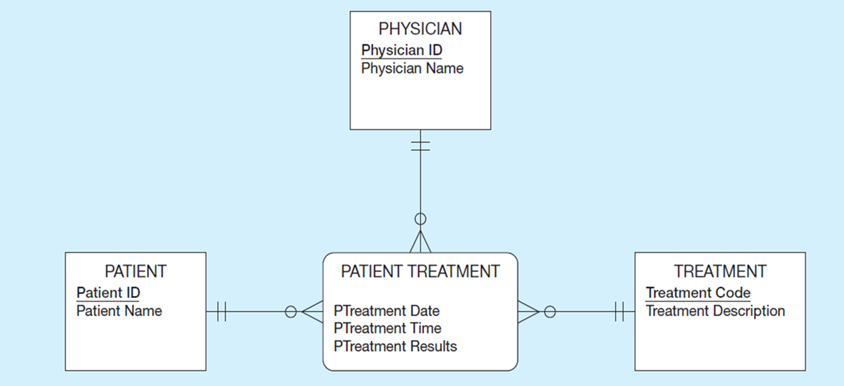
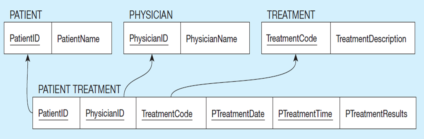
Primary Key Must be UNIQUE
Therefore needs more than just three foreign keys (explains why date and time are part of the primary key)
Physician may give the same treatment to the same patient multiple times, but only one at each date/time
Surrogate key preferable for large composite primary key
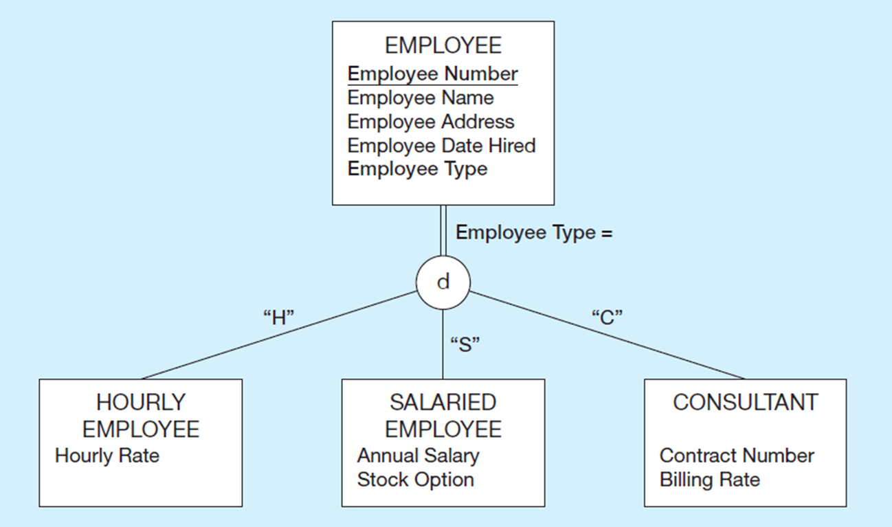
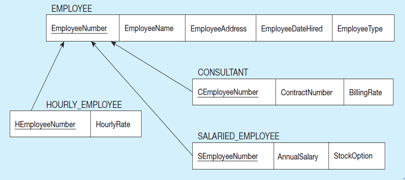
mapping supertype/subtype relationships
One relation for supertype and for each subtype
Supertype attributes (including identifier and subtype discriminator) go into supertype relation
Subtype attributes go into each subtype; primary key of supertype relation also becomes primary key of subtype relation
1:1 relationship established between supertype and each subtype, with supertype as primary table
Data Normalization
•Primarily a tool to validate and improve a logical design so that it satisfies certain constraints that avoid unnecessary duplication of data
•The process of decomposing relations with anomalies to produce smaller, well-structured relations

Well Structured Relations
Relations that contain minimal data redundancy and allow users to insert, delete, and update rows without causing data inconsistencies
Insertion Anomaly
adding new rows forces user to create duplicate data
Deletion Anomaly
deleting rows may cause a loss of data that would be needed for other future rows
Modification Anomaly
changing data in a row forces changes to other rows because of duplication
Steps in Normalization
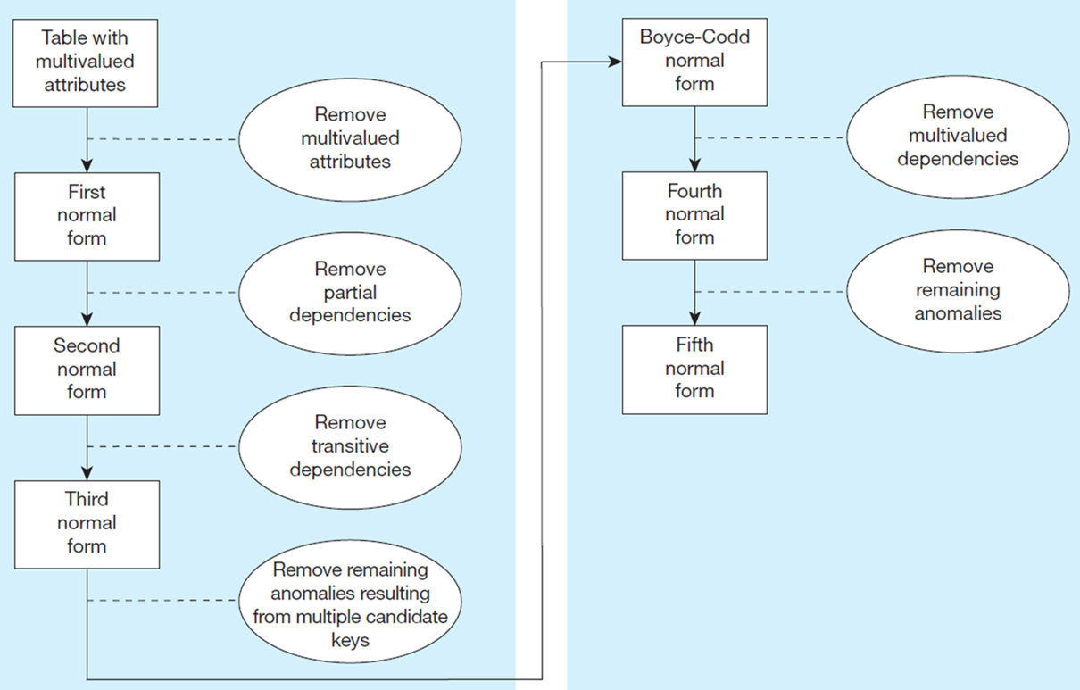
First Normal Form
•No multivalued or compositie attributes
•Every attribute value is atomic
•Fig. 4-25 is not in 1st Normal Form (multivalued attributes) → it is not a relation.
•Fig. 4-26 is in 1st Normal form.
All relations are in 1st Normal Form.

Not a relation

relation
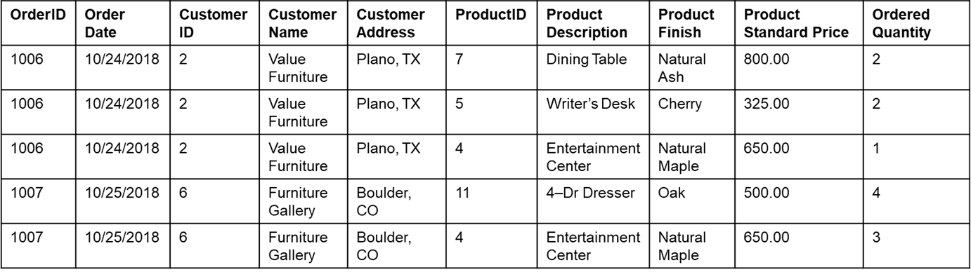
Second Normal Form
•1N F plus every non-key attribute is fully functionally dependent on the ENTIRE primary key
–Every non-key attribute must be defined by the entire key, not by only part of the key
No partial functional dependencies
1)Must be Normal form 2) Identify the primary key of the table and ensure each attribute is fully dependent on the ENTIRE primary key. (NO PARTIAL FUNCTION DEPENDIES). Could make into separate tables if data does not depend. Make several tables for everything that is not functionally dependent
2)Every attribute mut be fully dependent of the primary key of the table

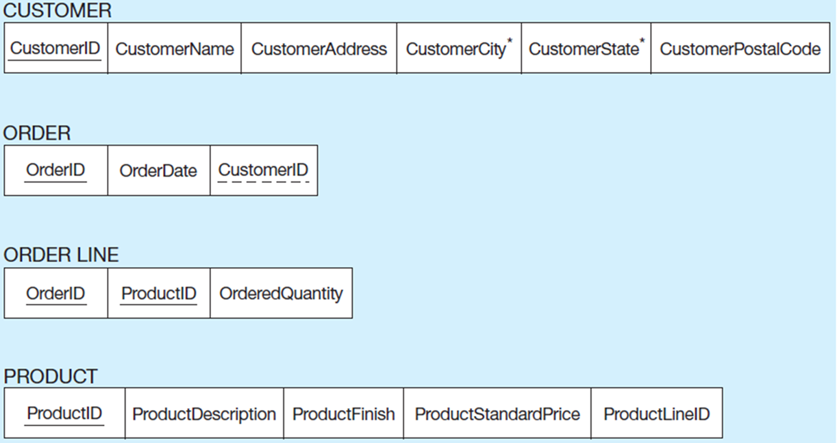
Not in 2NF
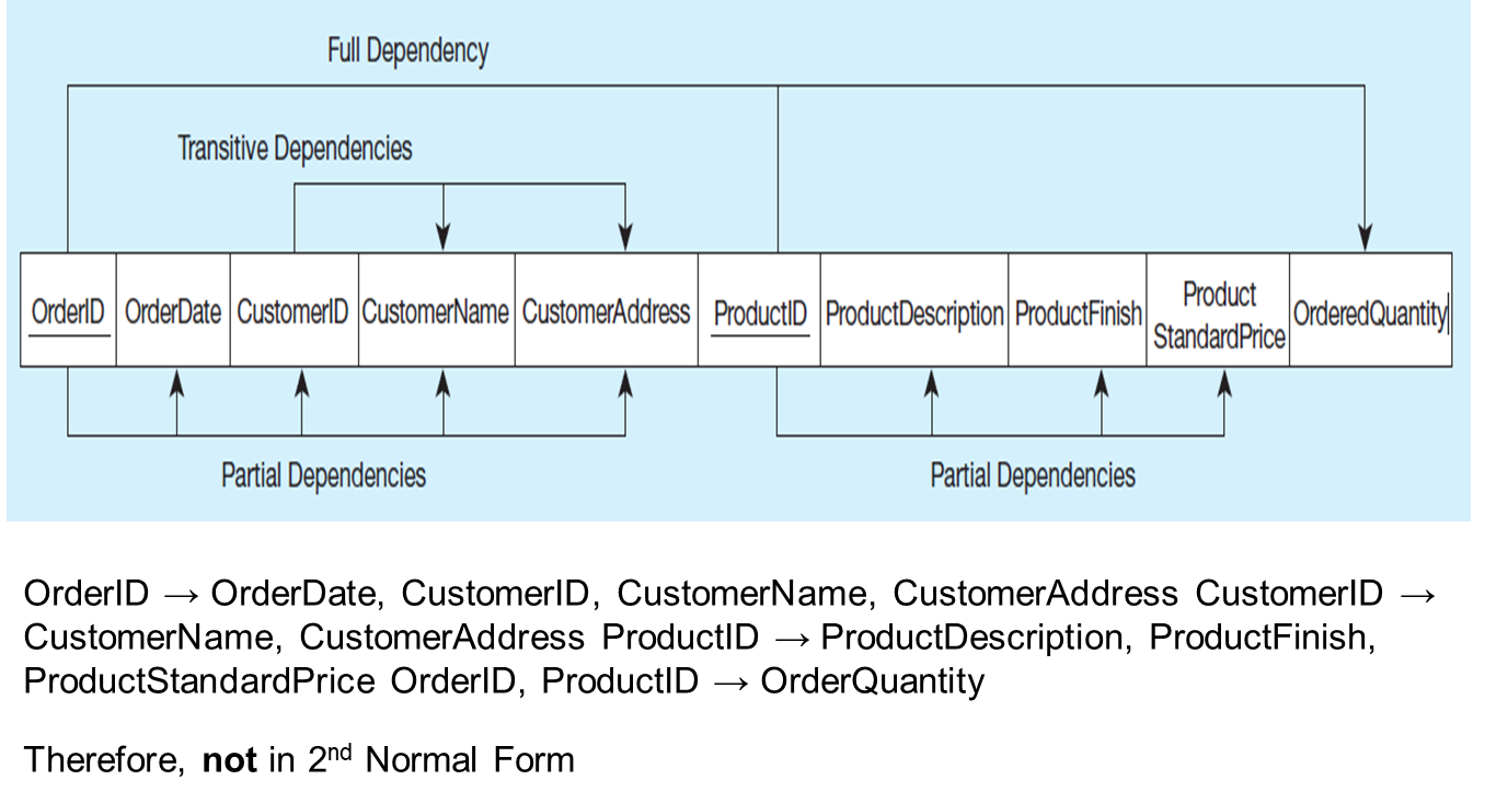
Remove the partial dependencies by splitting table into three, one for orders, one for products, and one for order line
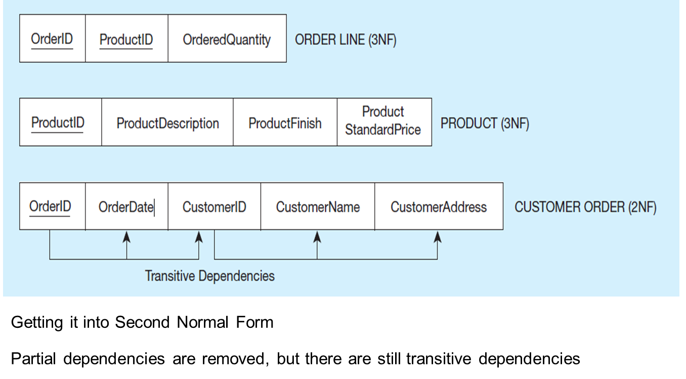
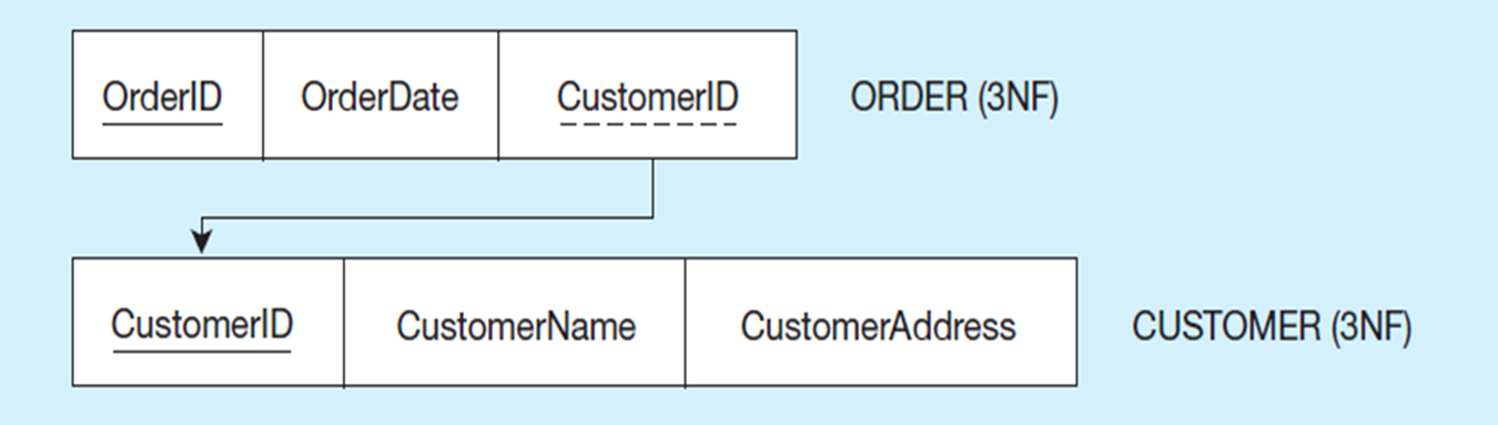
Third Normal Form
•2N F PLUS no transitive dependencies (functional dependencies on non-primary-key attributes)
•Note: This is called transitive, because the primary key is a determinant for another attribute, which in turn is a determinant for a third
•Solution: Non-key determinant with transitive dependencies go into a new table; non-key determinant becomes primary key in the new table and stays as foreign key in the old table
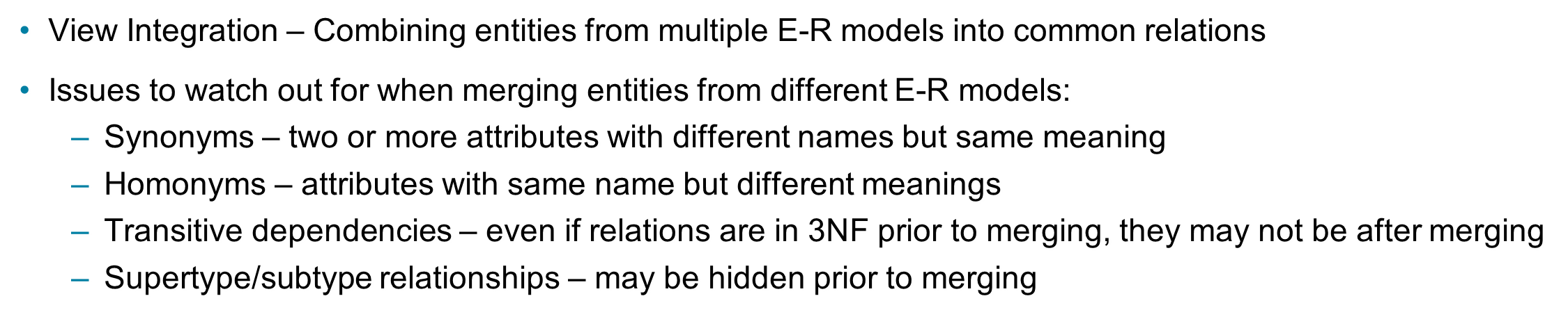
Merging Relations
•View Integration – Combining entities from multiple E-R models into common relations
•Issues to watch out for when merging entities from different E-R models:
–Synonyms – two or more attributes with different names but same meaning
–Homonyms – attributes with same name but different meanings
–Transitive dependencies – even if relations are in 3N F prior to merging, they may not be after merging
–Supertype/subtype relationships – may be hidden prior to merging