AS: MODULE2
1/19
There's no tags or description
Looks like no tags are added yet.
Name | Mastery | Learn | Test | Matching | Spaced |
|---|
No study sessions yet.
20 Terms
Beams
Structural members that carry transverse loads and are subjected to bending.
Statically Determinate Beams
eams where the number of unknown reaction components can be determined using the static equilibrium equations.
Equilibrium of Structures
– A structure is in equilibrium if it remains at rest when subjected to a system of forces and couples.
Static Equilibrium Equations
The three equations of equilibrium:
ΣFX = 0 (Sum of forces in the x-direction)
ΣFY = 0 (Sum of forces in the y-direction)
ΣM = 0 (Sum of moments)
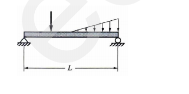
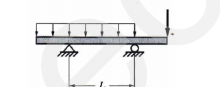
Simple Beam
A beam supported by a hinged reaction at one end and a roller support at the other end.
Overhanging Beam
A beam supported by a hinged and roller reaction, with either or both ends extending beyond the supports.
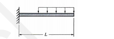
Cantilever Beam
A beam supported at one end only, with a suitable restraint to prevent rotation of that end.
Concentrated Load
A load acting over a very small distance and assumed to act at a single point.
Uniformly Distributed Load (UDL)
A load spread evenly over a length of a beam.
Uniformly Varying Load (UVL)
A load that is triangular in shape, where the intensity increases or decreases at a constant rate.
Positive Shear
A shear force that causes the left section of a beam to move upward relative to the right section.
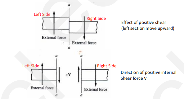
How to solve the shear value
If the summation of external forces is from left to right, upward forces is positive
If the summation of external forces is from right to left, downward forces is positive
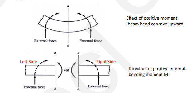
Positive Moment
A bending moment that causes a beam to bend concave upward at the section.
How to solve the bending moment value
I
f the summation of moment is from left to right, clockwise is positive
If the summation of moment is from right to left, counter clockwise is positive
shear force diagram
s a graphical representation showing the variation of the shear force along the
beam. It is drawn directly below the loading diagram.
bending moment diagram
is a graphical representation showing the variation of the bending
moment along the beam. It is drawn directly below the shear diagram.
Relationships between the load and shear diagrams
The slope of the shear diagram at a section along a beam is equal to the load intensity at the section.
2. The change in shear force between two sections along a beam is equal to the total load between tHe two sections.
Relationships between the shear and the moment diagrams
1. The slope of the moment diagram at a section along a beam is equal to the value of the shear force at
the section.
2. The change in bending moment between two sections along a beam is equal to the area under the
shear diagram between two sections.
Shear Diagram
The following procedure may be followed for sketching the shear diagram:
1. Draw the shear diagram directly below the loading diagram and use the same horizontal scale.
2. Starting at the left end, compute the shear at various controlling sections by adding the load on the next segment to the shear of the previous section.
3. Plot points on the shear diagram using the shear of each controlling section as the ordinate.
4. Connect the adjacent points plotted. Keep in mind that the slope of the shear diagram is equal to the load intensity. Find the location of the point of zero shears or the point where shear force
changes sign.
Moment Diagram
Draw the moment diagram below the shear diagram using the same scale.
Find areas under the shear diagram.
Add these areas step by step to get moment values.
Plot the moment values on the diagram.
Connect points smoothly with lines or curves.
Maximum or minimum moment occurs where shear is zero or changes sign.