week 9 simulation stuff
1/44
There's no tags or description
Looks like no tags are added yet.
Name | Mastery | Learn | Test | Matching | Spaced |
|---|
No study sessions yet.
45 Terms
Planning overview- combine machine parameters w…
individual patient data to customize and optimize treatment
Requires machine data, input of patient data, calculation algorithm
Produces output of data in a form which can be used for treatment (the 'treatment plan')
Radiotherapy is a localized treatment of cancer
know not only the dose but also the accurate volume where it has been delivered to.
applies to tumor as well as normal structures - the irradiation of the latter can cause intolerable complications. Again, both volume and dose are important.
What You Need to Know for Planning
Where the tumor is (location)
How big and what shape it is (volume & shape)
If it’s spreading nearby (secondary targets)
Where important organs are (critical structures)
Size & shape of those organs
How sensitive those areas are to radiation (radiobiology)
To find the tumor (target), we use diagnostic tools, like:
Basic tools:
Palpation (feeling the lump)
X-ray
Ultrasound
Advanced scans:
MRI
PET
SPECT
Planning scans:
CT scan
Simulator radiograph (used to help line things up for treatment)
Minimum Patient Data Needed
Target location: Where the tumor is
Patient outline: Shape and size of the body (for beam planning)
Simulator tools:
Laser system (for marking/positioning)
Optical Distance Indicator (ODI) — measures distance from machine to patient
Note: Some of these functions can now be done directly on the treatment machine too!
Role of Simulation
Used 2 times:
Plan it – Get patient info (tumor, body outline)
Check it – Make sure the plan works (verification)
Also for:
Reference images (to check setup later)
Can be replaced by virtual sim or other scans
Virtual Simulation
Treatment fields for
Uses CT scans + machine info to plan treatment
Done with software on a computer (not a real machine)
Virtual sim helps to
A CT scan of the patient is taken.
The scan is loaded into special software.
The team uses the software to:
Outline (contour) the tumor and organs.
Place the radiation beams in the best directions.
Add blocks/shields to protect healthy areas.
Plan where the skin marks (tattoos or stickers) go.
Simulator Film
Uses wires to outline the treatment field
Shows anatomy + field location + size
Shows shielding areas
Used as a reference image to check setup later
Patient Marking
Marks are placed to line up the patient with the beam
Connects the patient’s position to the machine’s coordinates
Helps make sure the beam hits the same spot every time
Combining Modalities – Easy Version
Look at scans side-by-side
Each scan shows different details
MR angiogram: shows blood vessels
MR image: shows soft tissues
Image Fusion – Easy Version
Combines images from scans like MRI or PET with CT
Why?
MRI/PET = better detail
CT = better location accuracy
Lets you outline anatomy on any scan and see it on the CT
To make a treatment plan, we need info about the beam and how it’s used:
Beam description: QUALITY and energy
Beam geometry: Machine angles (gantry, table, isocenter)
Field definition: How the beam is shaped (collimators, blocks, MLC)
Physical modifiers: Wedges, compensators
Dynamic modifiers: Moving parts like dynamic wedge, arcs, IMRT
Dose normalization: Sets the reference point for dose calculation
Machine Data for Planning – Easy Version
What’s needed depends on:
How complex the treatment is
What tools/resources you have to get the data
Data can come from:
Published sources
Your own measurements
Important: All data must be verified before using in planning!
Machine Data Acquisition – Easy Version
Data comes from:
The vendor or
Publications (like BJR 17 & 25)
But it must be verified first!
Done by a physicist using:
Dosimetry tools like water phantom, ion chambers, film, etc.
Documentation is a must — everything has to be recorded
Start of treatment planning is
Where beam is directed
Size beam
Shape
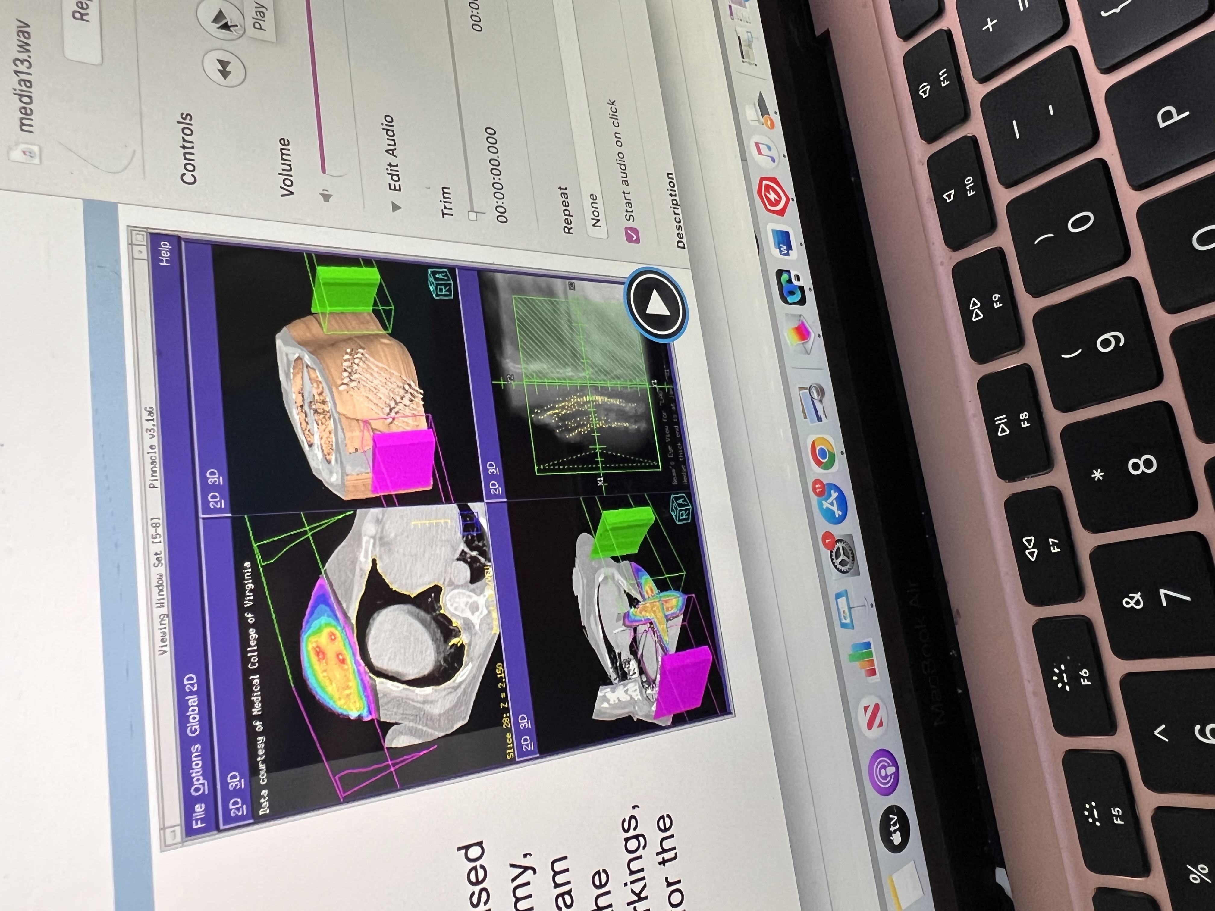
Beam’s Eye View (BEV):
A simulated image based on CT data that shows what the radiation beam “sees” as it enters the patient.
It represents the patient’s anatomy and defined treatment volumes from the beam’s perspective.
Helps with accurate beam alignment and planning.
Digital Reconstructed Radiographs (DRRs):
Images created from CT data that simulate an X-ray view of the patient.
Field placement and arrangement relative to patient
Based on Beam’s Eye View (BEV).
Include divergence-corrected anatomy (accounting for how the beam spreads).
Help guide patient setup and treatment accuracy.
Tools for Optimization:
These tools help shape the dose to match the tumor while protecting normal tissue:
Optimize treatment by bettering it by knowing
• Radiation quality – energy/type affects depth
• Entry point – angle to avoid critical structures
• # of beams – more beams = better dose shaping
• Field size – fits tumor, limits normal tissue
• Blocks – block beam from healthy tissue
• Wedges – tilt dose for even coverage
• Compensators – adjust dose for body shape
Beam Placement & Shaping – Approach
Many factors come into play w beam shaping
Entry point – where beam enters the body
• Field size – outline of the beam on the surface
• Blocks – shapes beam in to avoid normal tissue
• Wedges & Compensators – modify dose
Modern 3D mplanning incorporates additional strategies to enhance dose conformity and protect healthy tissues
Beam placement is a 3d approach need to know if
Multiple beams: Utilizing several beam angles to distribute the dose more evenly.
• Dynamic delivery: Adjusting beam intensity during treatment, as seen in Intensity-Modulated Radiation Therapy (IMRT).
• Non-coplanar beams: Delivering beams from different planes to better target complex tumor shapes.
• Dose compensation: Using advanced algorithms to modulate dose distribution, not just compensating for missing tissue.
• Biological planning: Considering tumor biology and tissue response to optimize treatment.
Dose-Volume Histogram (DVH
Key Features of an Optimal Target DVH:
• High Coverage at Prescribed Dose: Most of the target volume receives the intended radiation dose.
• Steep Drop-Off Beyond Prescribed Dose: The volume receiving doses higher than prescribed decreases rapidly, minimizing exposure to surrounding healthy tissues.
In radiation therapy, an ideal DVH helps visualize how radiation dose is distributed across different tissues.
Tumor (Target Volume)
High Dose to All: The entire tumor should receive the prescribed dose to ensure effective treatment.
• Homogeneous Dose: The dose should be evenly distributed within the tumor to avoid underdosing or overdosing specific areas
Critical Organ (Organ at Risk)
Low Dose to Most of the Structure: The majority of the critical organ should receive minimal radiation to reduce the risk of damage.
These DVH characteristics aim to maximize tumor control while minimizing exposure to surrounding healthy tissue
2D Conventional Radiotherapy
• Imaging: Utilizes orthogonal X-rays (anterior-posterior and lateral views).
• Planning: Based on anatomical landmarks; does not require CT scans.
• Beam Arrangement: Simple setups like the 4-field box technique, often used in emergencies (e.g., spinal cord compression).
• Limitations: Less precise targeting; higher exposure to surrounding healthy tissues.
3D Conformal Radiation Therapy (3DCRT)
• Imaging: Relies on CT scans to create a three-dimensional representation of the tumor and surrounding anatomy.
• Planning: Forward planning—clinicians manually design beam arrangements to conform to the tumor shape.
• Beam Arrangement: Multiple fixed beams shaped to match the tumor’s geometry.
• Advantages: Improved targeting compared to 2D; better sparing of normal tissues
Intensity-Modulated Radiation Therapy (IMRT)
Imaging: Advanced imaging (CT, MRI) for precise tumor and organ delineation.
• Planning: Inverse planning—computer algorithms optimize beam intensities to achieve desired dose distributions.
• Beam Arrangement: Multiple beams with varying intensities; can include dynamic delivery methods.
• Advantages: Highly conformal dose distributions; excellent sparing of critical structures; suitable for complex tumor shapes.
IMRT Delivery Technique
• Step-and-Shoot: Delivers radiation in multiple static segments; the beam is turned off while the multileaf collimator (MLC) adjusts between segments.
• Sliding Window (Dynamic MLC): Continuously moves MLC leaves during radiation delivery, allowing for more refined dose modulation.
In radiation therapy, once the target volume, beam orientation, and shape are determined, the next step is
calculate the appropriate beam-on time or monitor units (MUs) to deliver the prescribed dose to the target.
Forward Planning
Application: Commonly used in 3D Conformal Radiation Therapy (3DCRT).
• Process:
• The planner manually selects beam parameters, including angles, shapes, and modifiers.
• After calculating the resulting dose distribution, adjustments are made iteratively to achieve the desired coverage of the target while sparing healthy tissues.
• Characteristics:
• Relies heavily on the planner’s expertise and experience.
Inverse Planning
Utilized in IMRT to enhance dose conformity to complex tumor shapes.
• Process:
• The planner defines the desired radiation dose for the tumor and sets dose limits for nearby healthy structures.
• The planning system calculates the optimal intensity patterns for the radiation beams, adjusting the multileaf collimator (MLC) positions accordingly.
• This iterative process continues until the best possible plan is achieved, balancing effective tumor targeting with the protection of normal tissues.
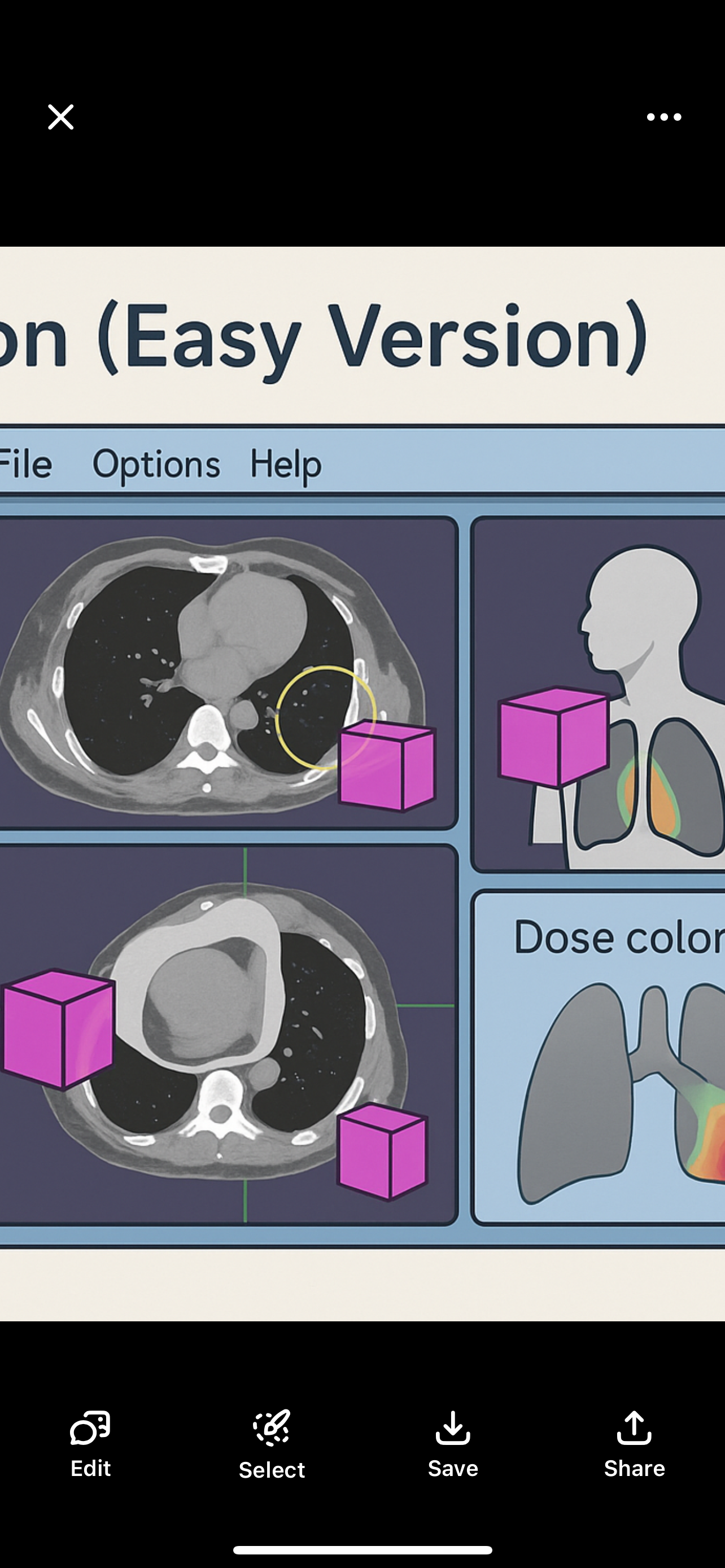
dose displsu options
ose display options
Dose interacting with patient cooor wash or dose painting
Diff colors diff percentages of dosesinilar to isodose lines
Photon beams
diverge and electron beams bulge at depth.
• This makes it hard to line up adjacent fields perfectly.
• If not careful, it can cause underdose or overdose at the junction
Used when: adjacent fields
• Fields are large or irregular
• Different beam energies are needed
• Treating previously radiated areas
Example: 10 MeV electrons used for deeper targets.
Abutting Fields – Simple & Easy
• Happen at the skin surface or deeper
• If they touch at the skin, beams overlap more at depth (due to divergence)
• Can cause hot spots (too much dose where they meet)
• Overlap can start just below the surface
• Always check tissue tolerances to avoid damage
Gaps – Simple & Easy
• Gap = space between two fields at the skin
• Fields meet (abut) at depth
• Used to avoid overdose where beams would overlap
• Lower dose is okay near the skin
• Helps spare tissue at depth by reducing hot spots
Feathering – Simple & Easy
• Feathering moves the junction during treatment to spread out dose
• Helps avoid hot spots (overdose) and cold spots (underdose) at field edges
• Prevents damage where dose exceeds normal tissue tolerance
• Gap area alone may not treat the tumor well
To avoid divergence:
• Use different jaws (e.g., close Y jaw in supraclav field)
• Adjust gantry, collimator, or couch angle to match field edges correctly
Abutting Fields: examples
• Bilateral Head & Neck with supraclavicular fossa field
• Tangential breast fields with supraclav field
gaps examples
• Craniospinal axis treatments (brain + spine)
• Mantle & para-aortic fields for lymphoma
Craniospinal Irradiation – Simple & Easy
What it treats:
• Whole brain and spinal cord (craniospinal axis)
Technique:
• 2 lateral brain fields
• 1 or 2 posterior spine fields
Positioning:
• Usually prone
• May need 3 spine fields if patient is long
• Use gaps at skin to avoid overdose
• May need feathering to blend junctions
Blocks:
• Help reduce divergence and protect normal tissue
Why Magnification Factor Matters:
• Helps adjust field size when no gradicule is used
• Tracks tumor changes (like shrinking or weight loss)
Key Points:
• Magnification Factor = correction used to get real size
• Depends on:
• Distance from object to source
• Distance from object to film
• It’s a measured ratio (like 1.05 or 1.10) to adjust for enlargement
Beam Divergence – Simple & Easy
• As the beam leaves the linear accelerator, it spreads out (diverges)
• More SSD = more divergence (due to inverse square law)
• Bigger field size = more divergence
Why We Account for Divergence:
• To know where the beam will go
• To protect nearby critical structures
• To adjust angles (collimator, couch, gantry) for better alignment
• Can use half-beam block (set one Y jaw to 0) to stop divergence on one side
Note:
• There is no divergence at the central axis (center of the beam)