Fluorescence of anthracene
 Call Kai
 Learn
Learn Practice Test
 Spaced Repetition
 Match
Match Flashcards
 Knowt Play
1/27

There's no tags or description
Looks like no tags are added yet.
Name | Mastery | Learn | Test | Matching | Spaced | Call with Kai | Chat |
|---|
No analytics yet
Send a link to your students to track their progress
28 Terms
fluorescence
light that is emitted by molecules after they are excited to upper (excited) electronic states, as they relax down to the ground electronic state; keeps the same spin orientation
linear combination of atomic orbitals - molecular orbital (LCAO-MO)
one model that describes the allowed energy levels of molecule
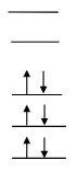
ground state (S0)
each molecular orbital contains 2 electrons, with their spins paired
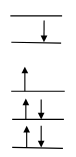
first excited state (S1)
obtained by promoting one electron from the highest occupied MO to the lowest unoccupied MO
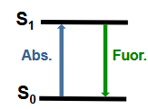
Fluorescence steps
1. A molecule absorbs a photon: Ground state (S0) + photon → singlet excited state (S1)
2. The excited state decays back to the ground state by emitting a photon: S1 → S0 + photon
3. There are a number of other, non-radiative pathways of decay of S1 to S0. (S1 → S0 + heat (No Fluorescence!))
4. The non-radiative processes compete with fluorescence.
High fluorescence intensity (yield)
Rate constant of fluorescence >> non-radiative rate constants
Low fluorescence intensity
Non-radiative rate constants >> rate constant of fluorescence
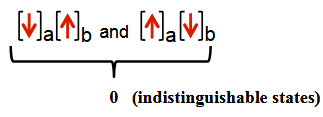
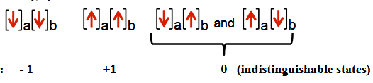
Singlet (1S) state
Only one spin state is possible with total spin angular momentum = 0
number of possible spin states (multiplicity)
2S + 1
triplet (3T) state
three distinguishable spin states, so that the possible values of the angular momenta are +1, 0, and -1
Radiative transitions
involve the absorption or emission of photons; energy of emission is always lower that that of absorption
Non-radiative transitions
excited state energy is dissipated in the form of heat; Excitation energy in excited states Sn is lost by collision with other molecules in their environment (e.g., solvent), or dissipation through internal vibrations that occur on a timescale of picoseconds to sub-nanoseconds thus generating heat; also called internal conversion; faster in liquids and solids than in gases
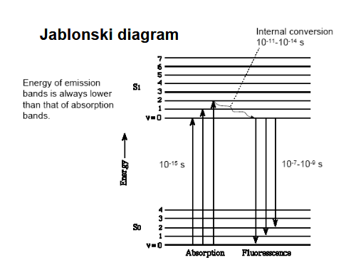
Jablonski diagram
describes and illustrates energy conversions in molecular energy levels; possible to excite the electron to higher molecular orbitals by shining light of higher and higher energy (shorter and shorter wavelength) on the molecule; Each state has a series of vibrational sublevels
Kasha’s rule
in almost all cases, emission is observed only from S1, the first excited state; If a molecule were excited to S3, for example, it would relax very quickly (within about 1 ps) to S1 before emitting: internal conversion; first order kinetics, like radioactive decay
phosphorescence
emission of light from T1 (first excited triplet state) to S0; spin flips
intersystem crossing (ISC)
process by which triplet states are usually populated from excited singlet states; enhanced by anything which favors spin flipping (spin-orbital coupling), such as the presence of “heavy atoms”; much longer lifetime and wavelengths than fluorescence
mirror symmetry
absorption: almost all of the molecules will be in the lowest vibrational state of S0 and we get a series of absorptions to different vibrational levels of S1
fluorescence: the molecule most always relaxes back to the lowest vibrational level of S1 before fluorescing. (Kasha’s rule.) However, once in that level, we can get emission to different vibrational levels of S0
highest energy emission band roughly corresponds to the lowest energy absorption band; this band is called (0,0).
symmetry will not be exact, because
(1) The vibrational spacings in the ground state and excited states will not be exactly the same
(2) The (0,0) in absorption will not correspond exactly to the (0,0) in emission
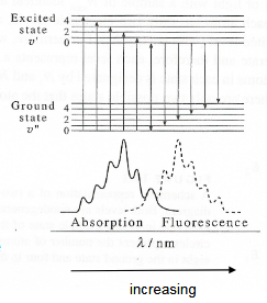
vibrational energy spacing
excited electronic state can be estimated from the absorption spectrum, and ground electronic state can be estimated from the fluorescence spectrum
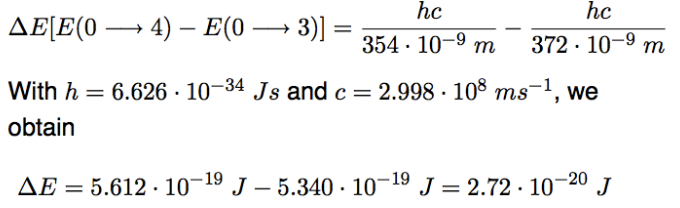
∆E = (4 + 1/2)hν′ − (3 + 1/2)hν′ = hν′
λ04 (S0, v = 0 −→ S1, v′ = 4) = 354 nm
λ03 (S0, v = 0 −→ S1, v′ = 3) = 372 nm
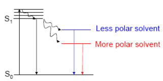
Stokes shift
emission is red-shifted; solvent before absorption stabilises ground state’s dipole/dispersion THEN rearrange themselves to stabilise excited state → lower the energy of excited singlet before emission
all fluorescence is strongly solvent dependent, but polar fluorophores are more solvent dependent
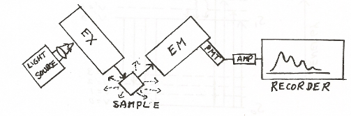
experimental setup
2 monochromators; adjust both the wavelength of excitation and wavelength of emission
To measure a fluorescence spectrum, we would set the excitation monochromator at some wavelength where the sample absorbs strongly, and then scan the fluorescence monochromator
vice versa for absorption spectra
(1) The “shape” of the fluorescence spectrum, i.e. relative numbers of fluorescence quanta at different wavelengths, should be independent of the excitation wavelength.
(2) The shape of the fluorescence spectrum should qualitatively resemble the shape of the absorption spectrum (remember: fluorescence intensity will be proportional to the amount of absorbed light).
Quenching
reacts with the fluorophore molecule in the excited state, and stimulates its decay to the ground state by a radiationless transition mechanism: the excited state energy is converted to heat and the fluorescence is ‘quenched’
fluorophores
molecules that are capable of emitting fluorescence after photoexcitation; sensitive to solvent and quenchers
Dynamic quenching
involves diffusional collisions between fluorophore and Quencher
S 1 + Q → S0 + Q + heat
static quenching
quencher forms a complex with the fluorophore before photoexcitation. The fluorescence quantum yield (Φ) is also diminished.
S0 + Q → [S0 ..Q]
[S0 ..Q] + hν → [S1 ..Q] → [S 0 ..Q] + heat
rate constants of decay
Radiative decay (fluorescence), rate constant kF
Non-radiative intersystem crossing, kISC
Non-radiative internal conversion to the ground state, kIC
Radiative decay from phosphorescence, kP
Non-radiative: Quenching, kQ
overall rate constant, kTOT , is the sum of all the individual rate constants
Flourescence quantum yield
phi0 = kF/k0 = tau0kf
observed fluorescence liftime in absence of quencher
tau0 = 1/k0 ~ 1 - 500 ns
Stern-Volmer equation
F0/F = 1 + tau0 kq[Q] = phi0/phiF
thus, plotting F0/F vs. [Q] = linear relationship w/ intercept of 1 = [Q]=0 and slope tau0 kq
![<p>F<sub>0</sub>/F = 1 + tau<sub>0</sub> k<sub>q</sub>[Q] = phi<sub>0</sub>/phi<sub>F</sub><br>thus, plotting F<sub>0</sub>/F vs. [Q] = linear relationship w/ intercept of 1 = [Q]=0 and slope tau<sub>0</sub> k<sub>q</sub></p>](https://knowt-user-attachments.s3.amazonaws.com/3eb341cb-9456-44a8-98fb-1a28df89a5e5.png)