Fluid & Heat transport KNW1
1/53
There's no tags or description
Looks like no tags are added yet.
Name | Mastery | Learn | Test | Matching | Spaced | Call with Kai |
|---|
No analytics yet
Send a link to your students to track their progress
54 Terms
IFT experiment
pull a frame out of a soap solution
measure the additional force required to pull the frame back by the distance ∆x
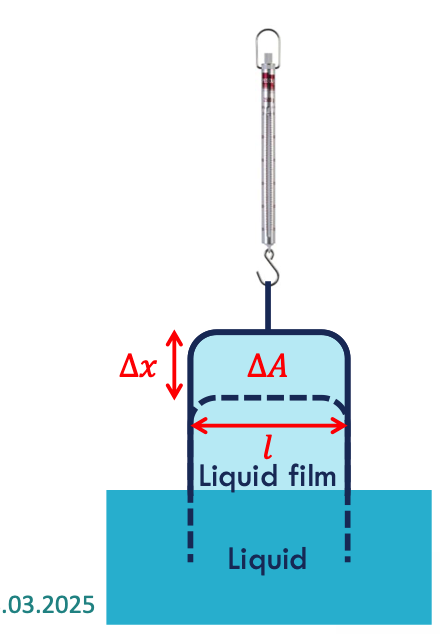
interfacial tension
the work required to enlarge the interface = The tension between two fluids
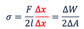
The factor 2 in the denominator comes from the two interfaces of a fluid film. The creation of two interfaces requires twice the work. [N/m]
Water-air system: ~73 mN/m
oil-brine system: 1 – 45 mN/m
surface tension
the tension at a liquid-air interface
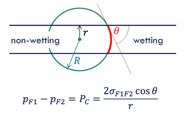
capillary pressure
the pressure between two immiscible fluids in a tube, resulting from the interactions of forces between the fluids and solid walls of the tube.
→ requirements for pressure difference between two immiscible fluid phases
interfacial tension
reason to form a curvature (contact of solid surface and wetting phase)
wettability
the tendency of one fluid to adhere to a solid in the presence of another fluid
wetting phase
When two immiscible fluids are in contact with a solid surface, one fluid is more strongly attracted than the other (contact angle on the denser side)
𝜃 = 0 → we have a complete water wet system
𝜃 < 90° → water wet
𝜃~90° → the system is intermediate or neutral wet
𝜃 > 90° → oil wet system
yong formula
𝛾𝐹1𝑆 = 𝛾𝐹2𝑆 + 𝜎𝐹1𝐹2 cos 𝜃
Laplace formula
∆𝑝 = 𝜎(1/𝑅1+ 1/𝑅2) = 𝜎𝐶
wetting factors
temp
oil brine composition
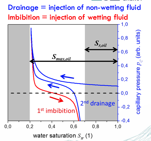
Capillary Pressure Curve
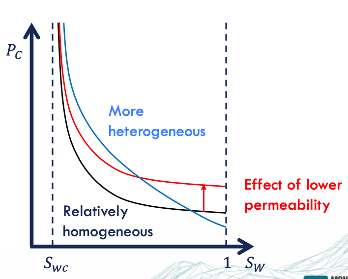
primary drainage = the pore size distribution (!) → the largest pores are invaded first - the smaller the pore throat, the higher the pressure required for the fluid to enter
Pc factors
low permeability = smaller pore throat = high Pc
high heterogeneity = wider pore throat = high Pc
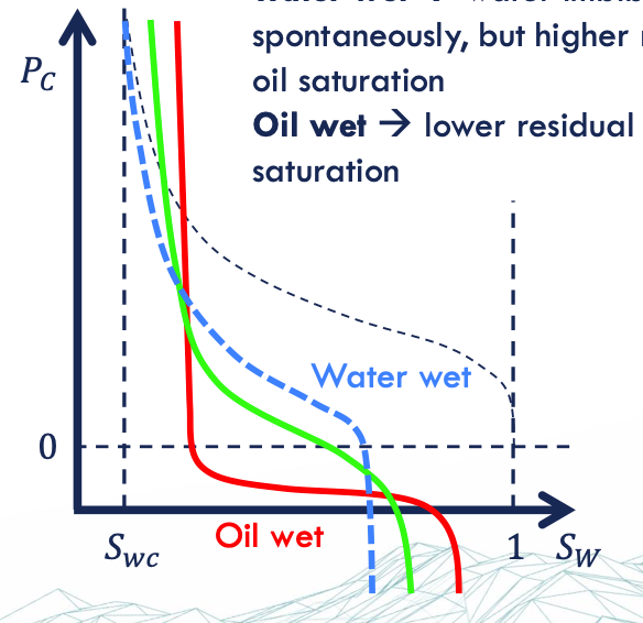
water wet = high Sor → spontaneous imbibition
oil wet = low Sor
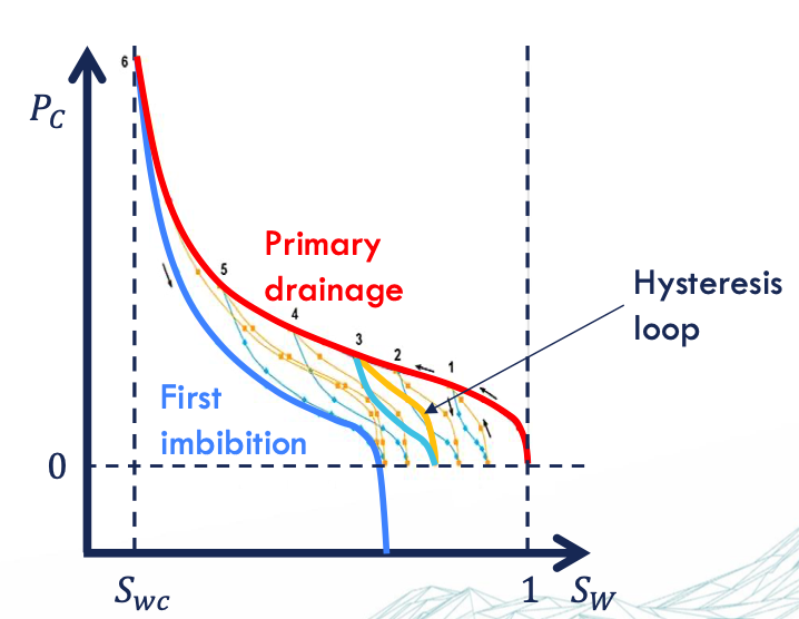
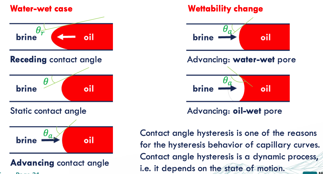
reasons of hysteresis
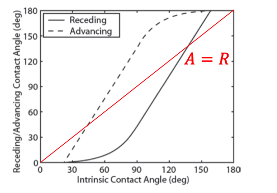
contact angle = receding vs advancing → depends on the state of motion
trapping mechanism
irreversible changes of interfacial area = dissipation
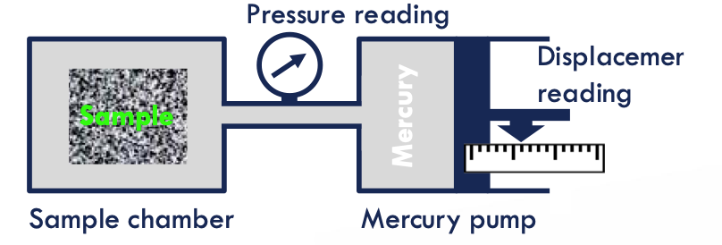
MICP measurements
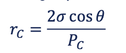
approximate the distribution of pore volume accessible by throats of given effective radii
place the sample in the equipment → evacuate the sample chamber
Pressure is increased in steps and the mercury intrusion volume is measured
Measurement up to 60,000 psi mercury pressure
Can handle irregularly shaped samples
Samples must be mechanically stable.

miscible displacement
both fluids are miscible in all proportions → single-phase flow with varying viscosity depending on mass fraction of mixture → the mixture has the full cross section in the pore space available for flow → no relative permeability effects, and no capillary pressure; mixing by diffusion and dispersion

immiscible displacement
no mutual phase participation and an interfacial tension (IFT) between the fluids
IFT leads to capillary pressure and relative permeability effects as function of fluid saturation 𝑆𝑤
the individual phases are not mixing in a miscible sense, but capillary pressure leads to dissipation

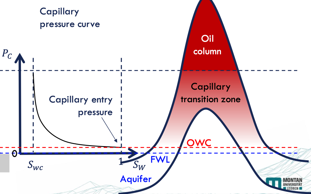
capillary pressure saturation functions
Saturation distribution of fluids in the pore space → Relative permeability
The saturation distribution in the reservoir
relative permeability saturation function
The microscopic displacement efficiency
The macroscopic sweep efficiency
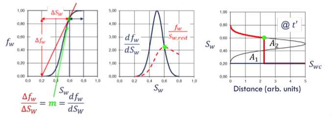
Pc + rel permeability saturation functions
The success of all oil and gas recovery operations
CO2 storage capacity and flow capacity
Production characteristics of a deep geothermal system (water-steam)
relative permeability curve functions
determines macroscopic saturation profile → the displacement efficiency.
Residual oil saturation provides → Ultimate recovery (after infinite time)
Curvature provides → Time scale of displacement, Injection pressure vs. injection rate
Saturations + hysteresis provide → Trapping potential
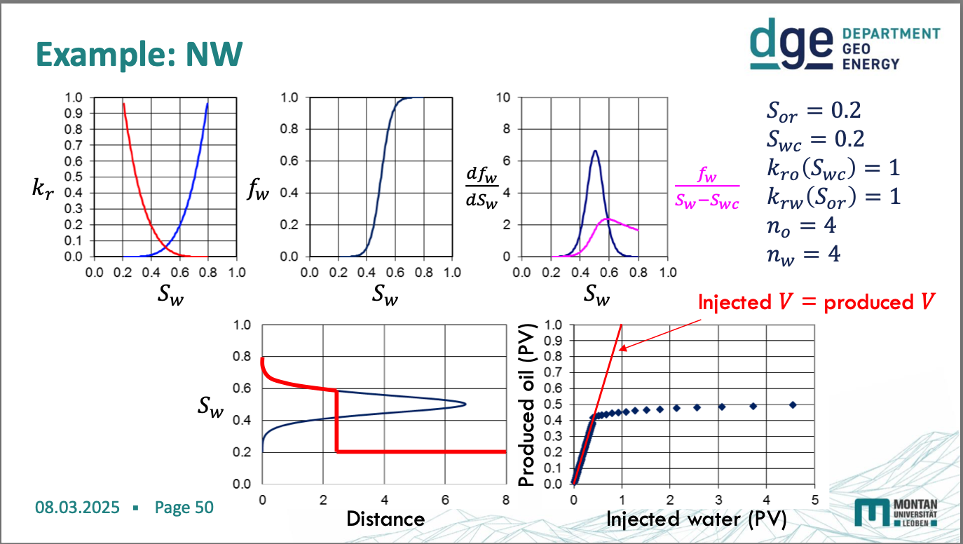
non-wetting diagrams
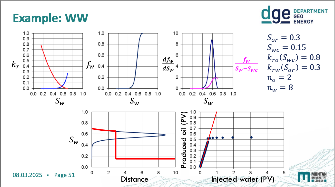
water wetting diagrams
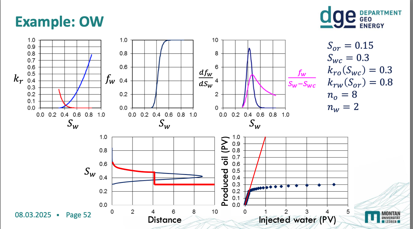
oil wetting diagram
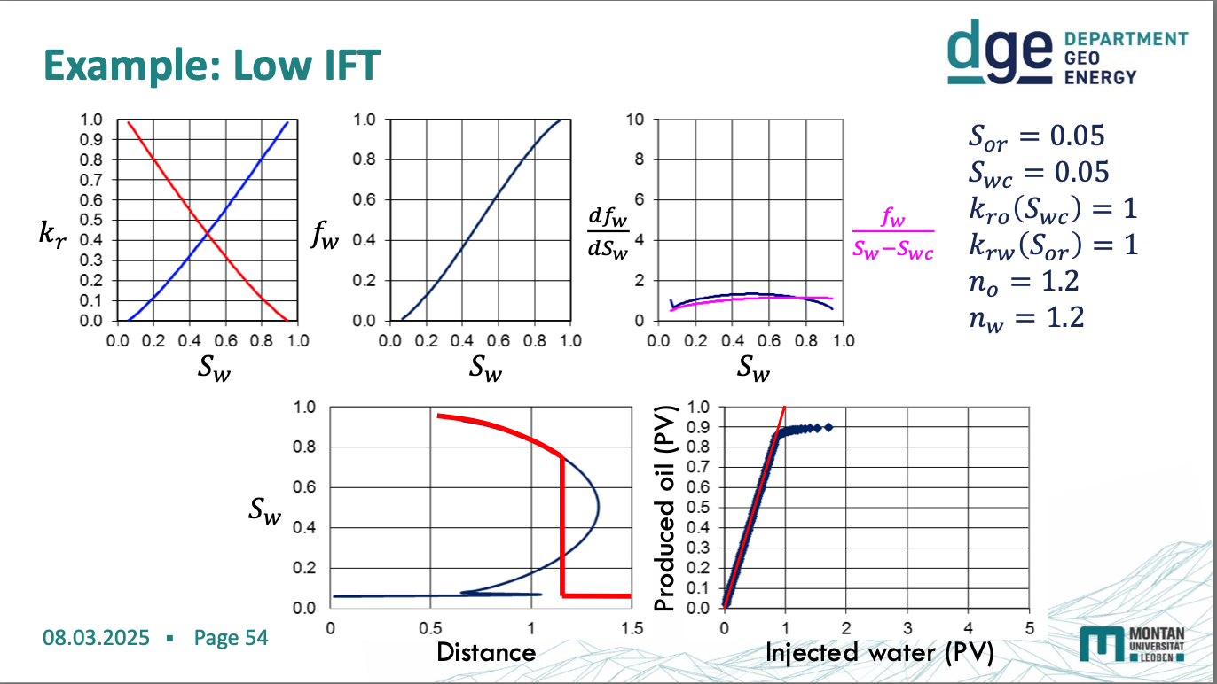
high IFT diagram
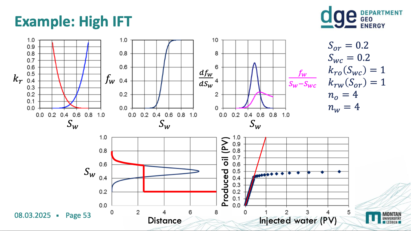
low IFT diagrams
navier stockes eq
describes the flow of incompressible newtonian fluids

steady state equation
hagen poseuille law
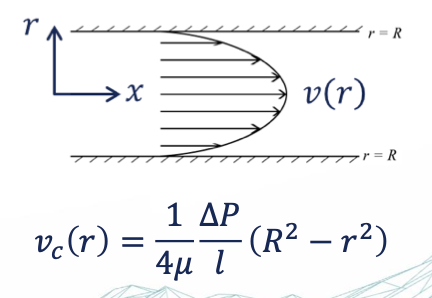
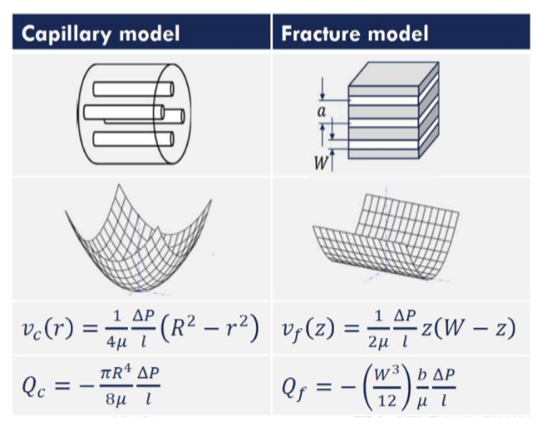
calculate the flow velocity in a single capillary (relative permeability)
gives the pressure drop (in an incompressible and Newtonian fluid) in laminar flow
flowing through a long cylindrical pipe with constant cross section
For viscous flow through a capillary tube with no-flow boundary conditions → flow velocity = 0 at
the wall
If the tube is small enough, a parabolic velocity field is forming at steady state
young Laplace eq
which capillary is occupied with which fluid phase (capillary pressure)
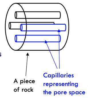
capillary bundle model (CBM)
a bundle of straight capillaries with a circular cross section of different ID, which represents the distribution of pore throats & Pc
→ explain the capillary transition zone in a hydrocarbon reservoir.
advantages:
simple w/ well defined geometry → symmetrically study flow in porous media & illustrate the meaning of certain complex concepts e.g. rel permeability
porosity formula
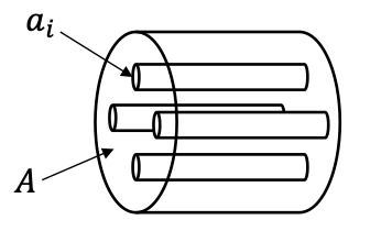
porosity = ∑ai/A
the volumetric flux (Q) is proportional to the open cross section
Q = qA = vavgøA = vavg∑ai = vavgnai
volumetric flux
discharge of a volume per time
Q = dV/dt [m3/s]
Darcy velocity
an average or equivalent velocity through a porous medium's volume, which includes both the solid matrix and the pore space through which water flow takes place
q = Q/A [m/s]
real/interstitial velocity
the speed at which the molecules of fluid are progressing in the direction of movement.
v = q/ø [m/s]
burdine equation
derive the relationship between capillary pressure and relative permeability in porous media by:
generalising the Hagen-Poiseuille law to capillaries of arbitrary cross section → extends the law to capillaries of arbitrary cross-section, making it more applicable to real-world porous media.
introducing tortuosity to describe the flow in tortuous capillaries → modifies the flow equations to reflect the actual resistance faced by fluids.
using the Young-Laplace law to couple the Poiseuille flow to the capillary pressure → links capillary pressure to fluid movement by integrating it with Poiseuille’s flow equation.
using empirical evidence to determine the shape of the relative permeability curves → connects to the Brooks-Corey model, which provides a power-law relationship between relative permeability and saturation.
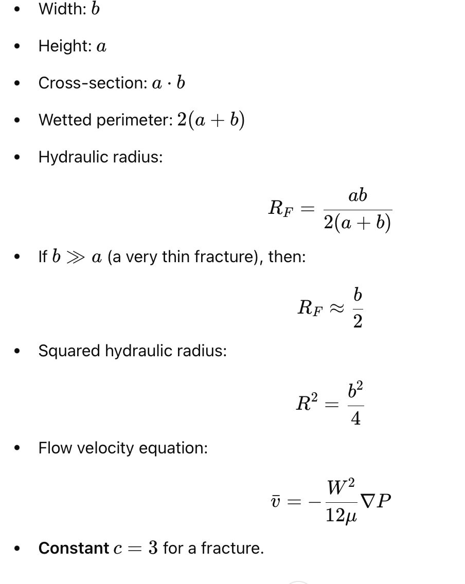
hydraulic radius, R → generalised hagen poiseuille eq
Hagen-Poiseuille equation describes laminar flow of an incompressible, Newtonian fluid through a cylindrical capillary:
Q=(πr4/8μL)ΔP
R = cross section area/ wetted perimeter => arbitrary cross section
Hagen-Poiseuille extreme cases
classical capillary = circular tube
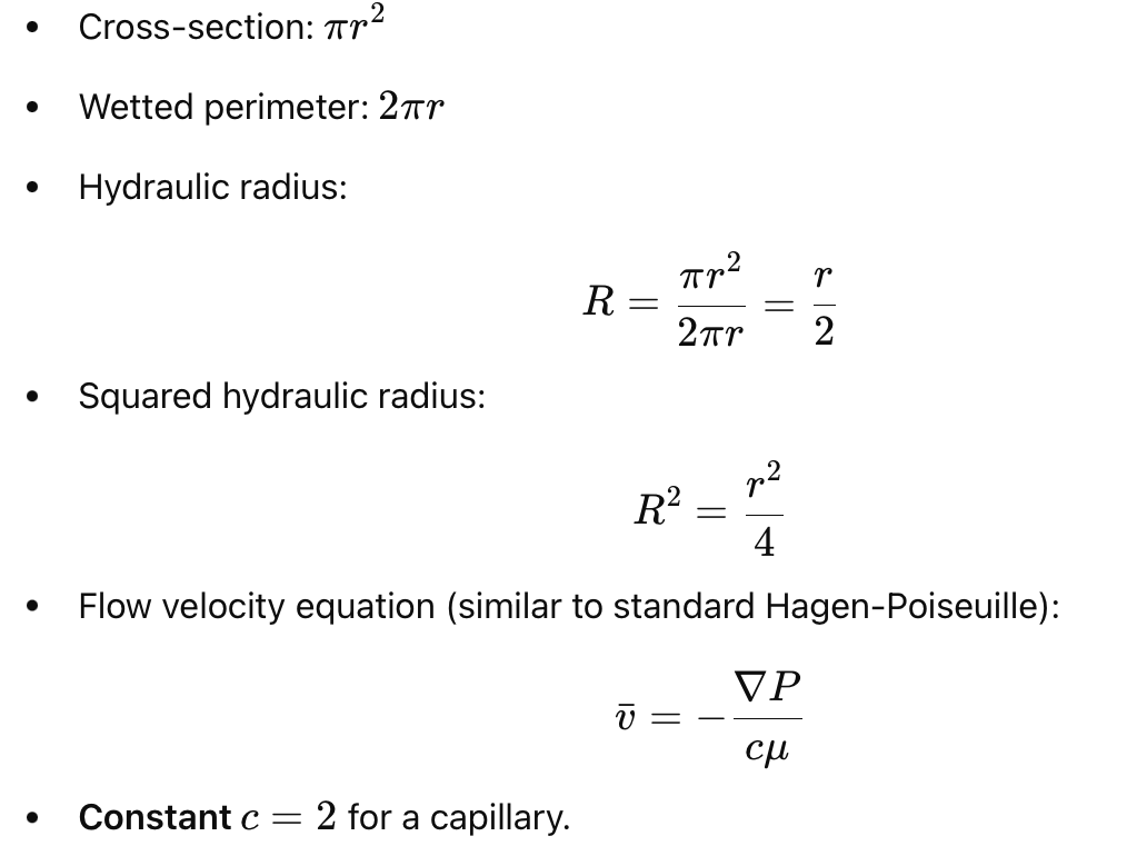
fracture flow = parallel plate approximation
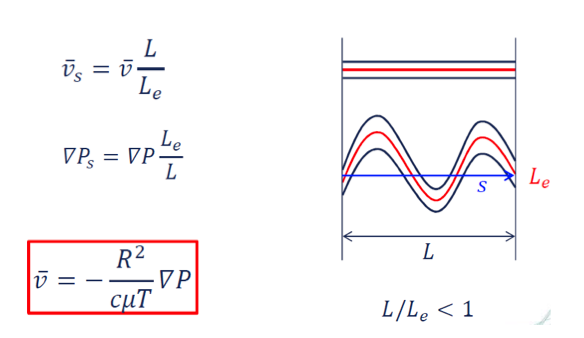
tortuosity
how fluid flow in porous media deviates from a straight path due ti the complex geometry of the rock structure
Straight velocity is smaller than the local velocity on a tortuous path
Straight driving force most be larger than the local driving force on a tortuous path
!! actual average velocity 𝑣𝛼 is double to the interstitial velocity 𝑣 at a given volume flow 𝑄 or Darcy velocity 𝑞 !!

capillary pressure effects
inetrfacial properties
microscopic hydraulic properties
microscopic rock structure
leverett function
a way of expressing capillary pressure in dimensionless form, originally proposed for intergranular clean sands, relating 𝑃c to porosity, permeability, IFT, and contact angle. It removes these properties from the 𝑃c(𝑆w) curve and makes curves of the same rock type comparable – different rock types
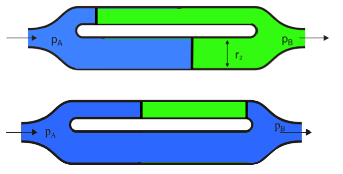
viscous dominated flow
external force → the pressure difference is given from the outside (viscous pressure drop) = cause of flow
the fluid flows against the pressure difference.
large scale flow
he flow velocity is greater in the large diameter channel → oil is bypassed and trapped in the smaller pores.

capillary dominated flow

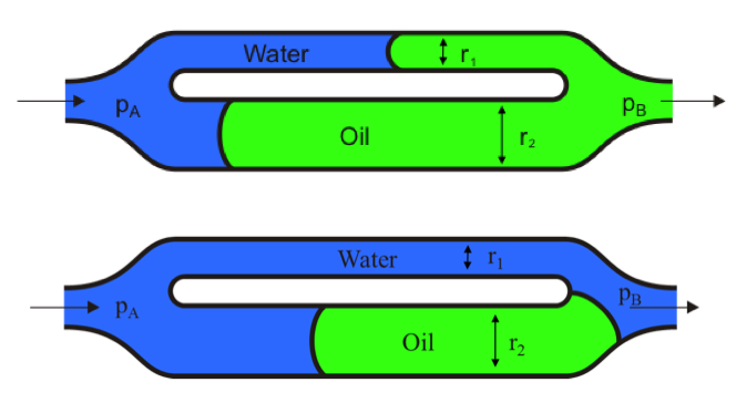
intrinsic force → the pressure difference across the oil/water interface = effect of capillary force
act on small pore scale
Imbibition is driven by capillarity, which is stronger in the smaller channel → some oil is bypassed and trapped in the larger channel.
jamming effect
when oil droplets become trapped in capillary tubes due to interfacial forces.
trapped oil
When oil is present in a capillary tube surrounded by water, it may become trapped because the pressure required to push it through is higher than typical viscous forces. → These trapped oil droplets are isolated and no longer experience continuous pressure from the bulk oil phase.
snap off model

how the non-wetting phase (oil) becomes disconnected into isolated droplets during imbibition (when the wetting phase, water, invades a porous medium).
In water-wet (WW) systems, water preferentially coats the pore walls, forming a thin water film around the oil phase.
As more water enters the pores, capillary-driven flow moves water into pore throats (narrower regions between larger pore bodies).
When water accumulates in pore throats, it creates high capillary pressure contrasts between the pore throat and the larger pore body.
A large capillary pressure difference (PCPC) between the pore throat and pore body is required for snap-off.
If the pore size to pore throat size ratio is greater than 2, the pressure contrast becomes large enough to break the continuity of the oil phase.
This causes the oil column to snap, isolating the non-wetting phase (oil) into individual droplets or ganglia.
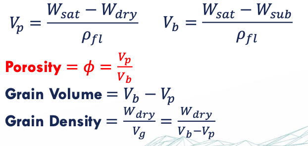
porosity
ratio of pore volume to bulk volume 0<ø<1
ø = Vp/Vb
archimedes’ principle
Any body partially or completely submerged in a fluid is buoyed up by a force equal to the weight of the fluid displaced by the body
archimedes experiment
Weigh clean and dry sample → 𝑊 𝑑𝑟𝑦
Saturate sample with e.g. toluene or chloroform under vacuum → weigh sample → 𝑊 𝑠𝑎𝑡
Submerge sample in in the same fluid → weigh submerged sample → 𝑊 𝑠𝑢𝑏
oswald viscometer
determines flow through a capillary, following Hagen Poiseuille´s law by measuring the time it takes the fluid level to decrease form A to B
→ 𝜇 = 𝑐𝑡

viscometers
Ostwald viscometer
falling ball viscometer
Viscometers for Complex Rheology
Rotational viscometer with two co-axial cylinders- the fluid sample is in the annulus space in between the cylinders.

core flooding conditions
laminar flow regime
no reaction between fluid and rock
single fluid phase
multi rate core flooding
Injection rates (𝑄): set by the pump and are typically very accurate using high precision displacement pumps.
Core geometry (𝐴 and 𝐿): measured before the experiment very accurately.
Fluid viscosity: it is important to take experimental temperature into account – measurement typically very accurate.
The differential pressure measurement depends on the quality and calibration of the device → multi rate measurements are required to eliminate offsets of the pressure gauges and for higher precision.
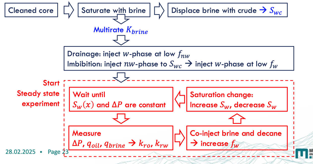
The Steady-State Method
two immiscible liquids are simultaneously injected into a core in a specific ratio and at a constant total flow rate until a flow equilibrium
The steady state is reached when the pressure difference across the core and the saturation profile in the core are constant over time

after the steady state is reached and saturation and pressure measurements have been taken, the water/oil injection ratio is adjusted to reach a new fractional flow and a new saturation state.


saturation monitoring
monitoring production the volume of produced fluid

X-ray shadowgraphy - in-situ saturation monitoring

Preparation of an Steady State Experiment
