UT 200 - Artifacts
1/94
There's no tags or description
Looks like no tags are added yet.
Name | Mastery | Learn | Test | Matching | Spaced | Call with Kai |
|---|
No analytics yet
Send a link to your students to track their progress
95 Terms
causes of artifacts
physics of ultrasound
operator errors
improper equipment operation or settings
violation of imaging assumptions
equipment malfunction
imaging assumptions
sound travels in a straight line
sound travels directly to the reflector and back
sound travels in soft tissue at exactly 1540 m/s
reflections arise only from structures positioned in the beam’s main axis
imaging plane is very thin
strength of the reflection is related to the characteristics of the tissue creating the reflection
axial resolution artifact occurs when
long pulse strikes two closely spaced structures, where one is in front of the other, and the two structures combine into one form
for axial resolution artifacts, the images are closer than what size?
½ SPL
different names for axial
longitudinal, axial, range, depth
is axial resolution constant with depth?
yes
how to minimize axial resolution artifacts
transducer design: shorter pulses = higher frequency transducer and increased damping material
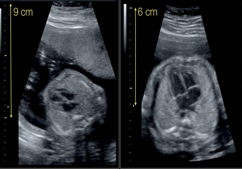
which image has a greater axial resolution and why?
the image on the right; it uses a higher frequency probe which results in greater axial resolution
lateral resolution artifacts occur when
a pair of side-by-side reflectors are closer than the width of the sound beam, thus appearing as one
definition of lateral resolution
ability to resolve two structures positioned perpendicular to the sound beam
other names for lateral resolution
longitudinal, azuthimal, transverse, angular
where is lateral resolution artifacts least likely to occur
at the focus of the sound beam where the beam is smallest
the third dimension is dependent on
slice thickness or elevation
reflectors in the 3rd dimension appear as
sludge or debris
slice thickness artifact is due to
transducer design
how to improve slice thickness artifacts
making the imaging planes thinner through focusing with acoustic material (mechanical) or harmonic imaging
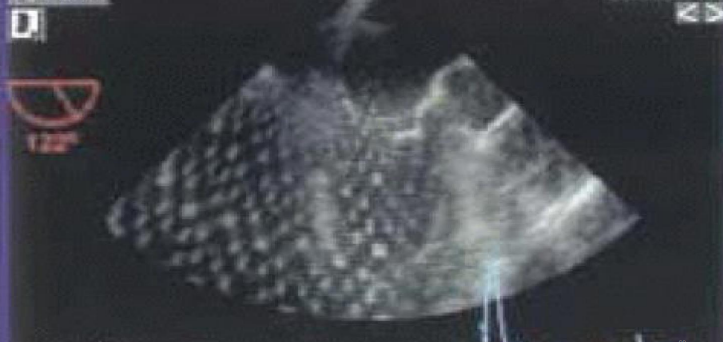
what type of artifact?
slice thickness artifact
acoustic speckle looks
bright grainy speckled appearance; like a pseudo tissue texture
acoustic speckle results from
constructive and deconstructive interference of small wavelets
what depths are degraded by acoustic speckle
shallow depths; low contrast structures near the transducer are more difficult to image
what can be used to reduce acoustic speckle
standoff pads
on a machine, what can operators turn on reduce acoustic speckle
speckle reduction
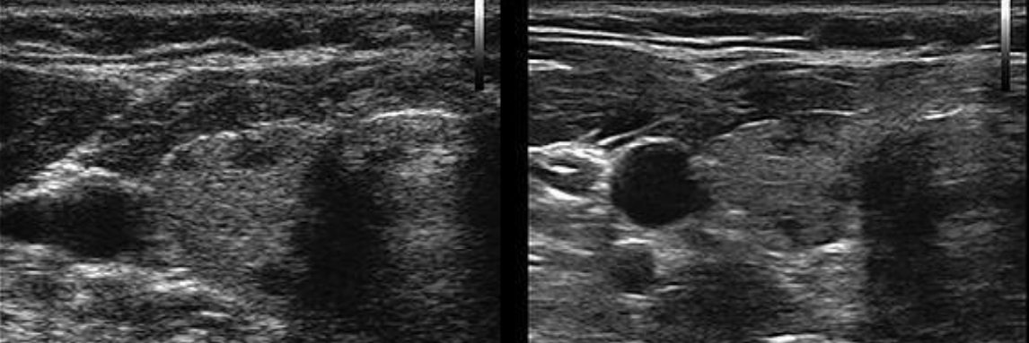
what type of artifact is this and what did we use to fix it on the image to the right
acoustic speckle; turned on speckle reduction on the machine
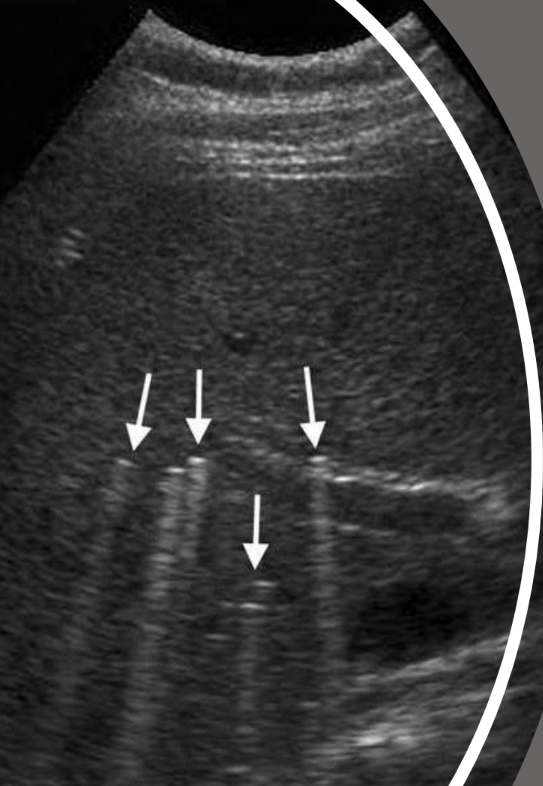
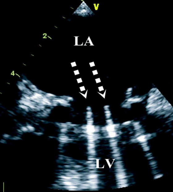
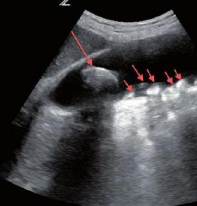
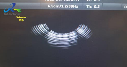
reverberation is caused by
bouncing of sound waves between two strong reflectors positioned parallel to the ultrasound beam
if there’s reverberation artifact, how many reflections will you see?
multiple
in reverberation artifacts, how are the reflections arranged
in a ladder; each reflection is located at ever-increasing depths
what are the two types of reverberation artifacts?
comet tail
ring down
what type of artifact is this?
reverberation artifact
what is the difference in reflection location in slice thickness artifacts and reverberation artifacts?
slice thickness artifacts occur at the posteriorly
reverberation artifacts occur anteriorly
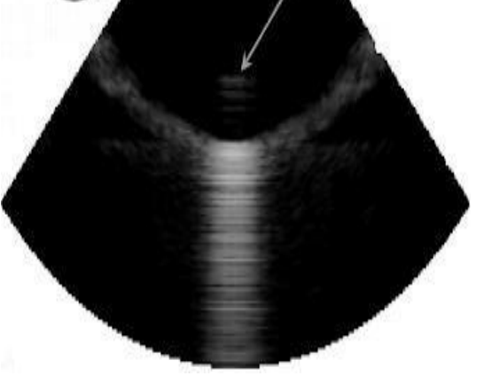
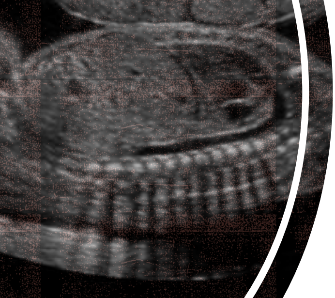
what type of artifact is this?
ring-down artifact
where do ring-down artifacts occur?
in air sacs, caused by small air bubbles
what type of artifact is this?
comet tail artifact
what are comet tail artifacts caused by?
mechanical objects within the body
how do we rectify ring-down artifacts?
changing our scanning angle
refraction artifacts occur when
the ultrasound beam changes direction (bends) during transmission after striking a boundary obliquely with 2 different propagation speeds
where is the duplicated structure seen on an image for refraction artifacts?
side by side at the same depth as the real structure (lateral displacement)
how to rectify refraction artifacts?
changing the scanning angle
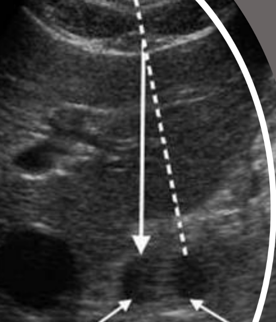
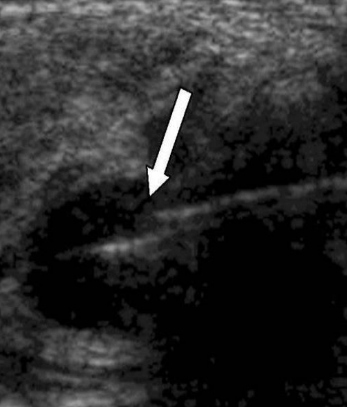
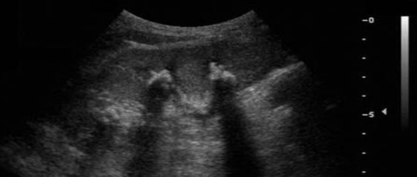
what type of artifact is this?
refraction artifact
would you be able to distinguish the refraction artifact from the real structure using Doppler?
NO. both structures will fill with color and spectral dopplers signal within both
multipath artifact occurs when
sound pulses glance off a second structure on the way to and from the primary reflector
where is the artifact reflector placed in a multipath artifact?
deeper than its correct position (axial displacement)
how to rectify multipath artifacts?
changing the scanning angle
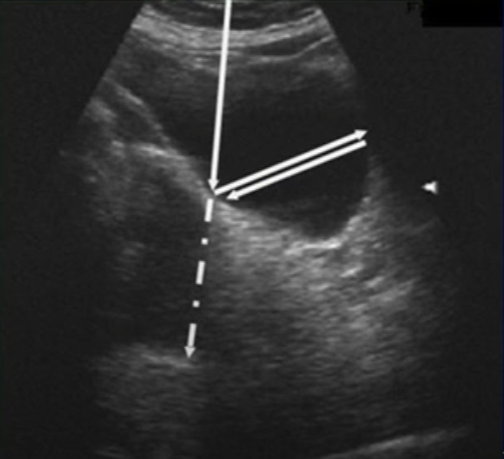
what type of artifact is this?
multipath artifact
mirror image artifact occurs when
sound reflects off a strong reflector (mirror) and is redirected towards a second structure
what kind of structure does a mirror image artifact create?
a weaker duplicate structure deeper on the opposite side of the reflector
how are mirror artifacts rectified?
changing the scanning angle
what type of artifact is this?
mirror image artifact
what types of transducers create side lobes and grating lobes?
side lobes - single crystal transducer
grating lobes - arrayed (multicrystal) transducers
where are the fake reflections placed in lobe artifacts?
placed at the correct depth but incorrect lateral position
what type of artifact is this?
side lobe artifact
are grating lobes seen much these days? why or why not?
no, they’re not common
subdicing (splitting the crystals) and apodization (exciting center elements with higher voltages than outer elements)
range ambiguity occurs when
echoes from one pulse return after another pulse has been transmitted
how do we rectify range ambiguity artifacts?
increasing the depth or lowering PRF
what do range ambiguity artifacts look like?
a grayish haze near the transducer
what kind of artifact is this?
range ambiguity artifact
what happens when sound waves travel through mediums with a propagation speed that ISNT 1540 m/s
systems displays the structures at incorrect depths
what type of artifact appears as “split” or “cut?”
propagation speed error artifacts
propagation speed errors are also known as
range error artifacts
if propagation speed >1540 m/s, echo returns —— and assumes the structure is —— than where it really is
faster; shallower
if propagation speed is <1540 m/s, echo returns —— and assumes the structure is —— than where it really is
later; deeper
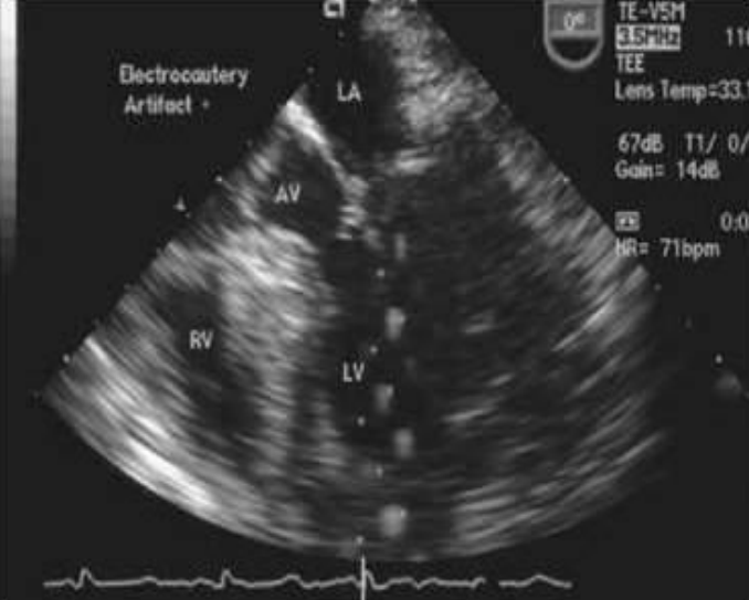
what type of artifact is this?
propagation speed error artifact
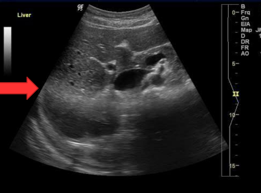
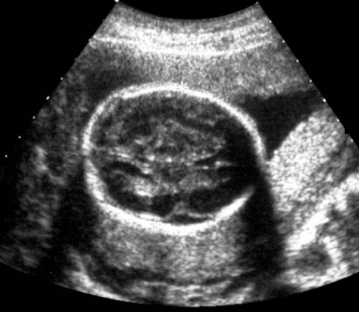
acoustic shadowing occurs when
the attenuation is higher in the tissue above the shadow than in the surrounding tissue
for acoustic shadowing, the sound beam must hit a —— attenuating/reflecting structure, such as:
highly
bone, calcified plaque, metal objects, etc.
T or F: for acoustic shadowing, sound beams are mostly reflected back to the transducer, with little transmission
true
clean shadowing is characterized by:
posterior to calcification or bone
high levels of absorption/reflection
NO transmission
dirty shadowing is characterized by:
posterior to air-filled structures
high percentage of reflection
small percentage of transmission
what type of artifact is this?
clean acoustic shadowing
what types of artifacts can be diagnostic?
acoustic shadowing
acoustic enhancement
what type of artifact is this?
clean acoustic shadowing
what type of artifact is this?
clean acoustic shadowing
what type of artifact is this?
dirty acoustic shadowing
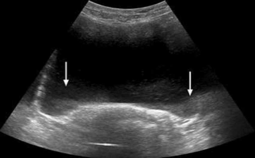
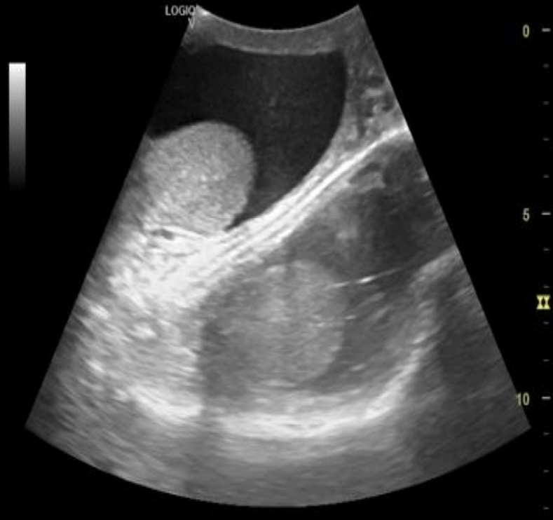
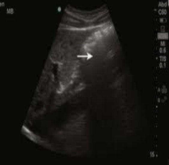
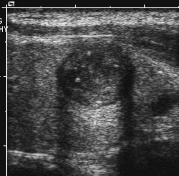
acoustic enhancement appears as
a hyperechoic region beneath tissues with low/weakly attenuating structure; abnormally increased brightness posteriorly
opposite of shadowing
enhancement
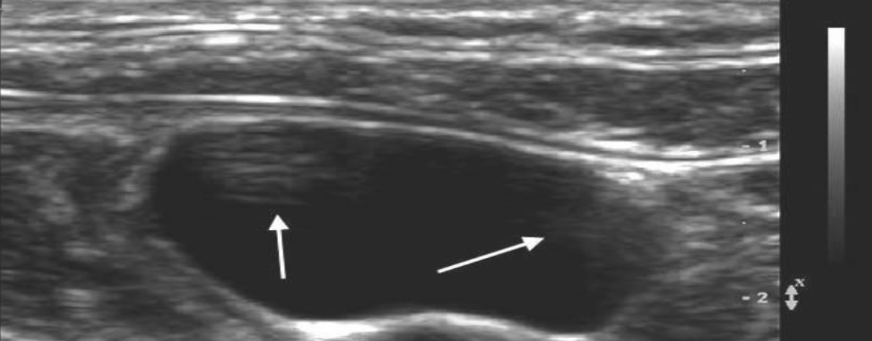
what type of artifact helps diagnose cystic from solid masses?
acoustic enhancement
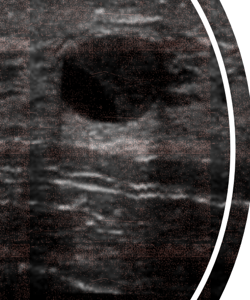
what type of artifact is this?
acoustic enhancement
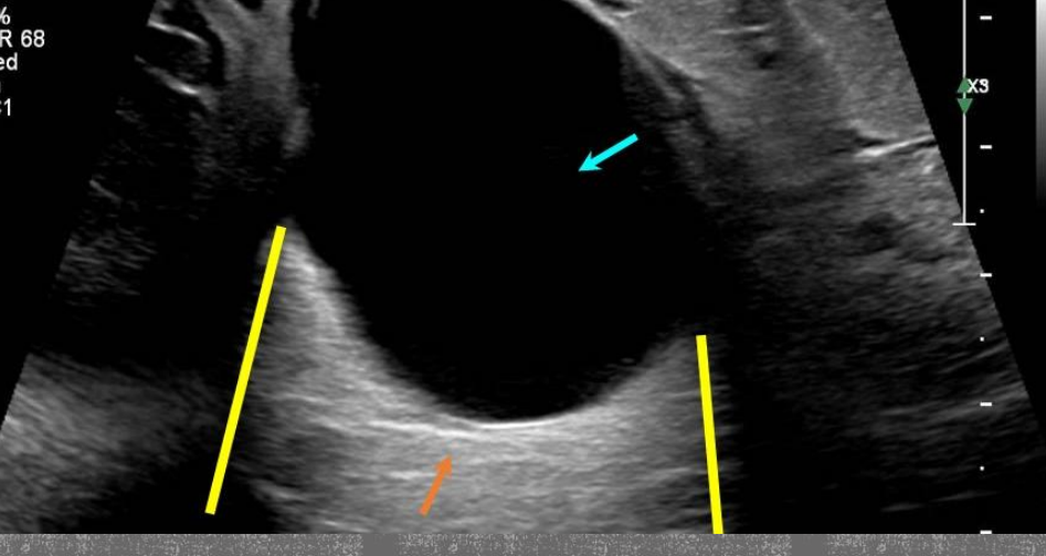
what type of artifact is this?
acoustic enhancement
another name for focal enhancement
focal banding
what does focal enhancement look like?
side to side region of an image that appears brighter than tissues of other depths
how to rectify focal enhacement?
altering the focal zone or increasing the # of focal zones
what type of artifact is this?
focal enhancement/banding
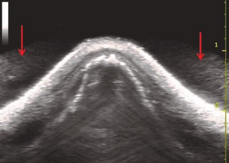
edge shadowing is also known as
refractive edge shadowing
edge shadowing occurs when
ultrasound beam refracts (bends) at the edge of a curved reflector
what does edge shadowing appear as?
hypoechoic region extending down from the edge of a curved reflector
what type of artifact is this?
edge shadowing
what type of artifact is this?
edge shadowing
relationship between coarseness of speckle pattern and transducer frequency
inverse
coarseness decreases as frequency increases
instrument/electronic noise is caused by
electrical interference from nearby equipment
what do instrument/electronic noise appear as?
arcs of vibrating bands across a monitor
is instrument/electronic noise present when an image is frozen?
NO; it’s only present when image is in motion
what is this type of artifact?
electronic noise
what is this type of artifact?
electronic noise
what happens when there’s inadequate TGC?
horizontal bands of varying brightness on the image
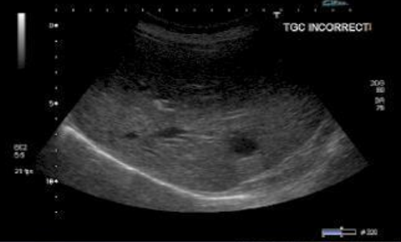
what is this type of artifact?
inadequate TGC artifact
what will we see if there’s dead crystals on the transducer?
vertical dark bands appearing on the image
what type of artifact is this?
dead crystals artifact