Lecture 3: IMAGING CONTRAST/DENSITY, RECORDING MEDIAS
 Call Kai
 Learn
Learn Practice Test
 Spaced Repetition
 Match
Match Flashcards
 Knowt Play
1/33

There's no tags or description
Looks like no tags are added yet.
Name | Mastery | Learn | Test | Matching | Spaced | Call with Kai | Chat |
|---|
No analytics yet
Send a link to your students to track their progress
34 Terms
Image Density:
Defined as the degree of darkening on a film (not tissue density)
Image of high density is dark, image of low density is light. When more photons reach an image receptors, density increases, with fewer photons, density decreases.
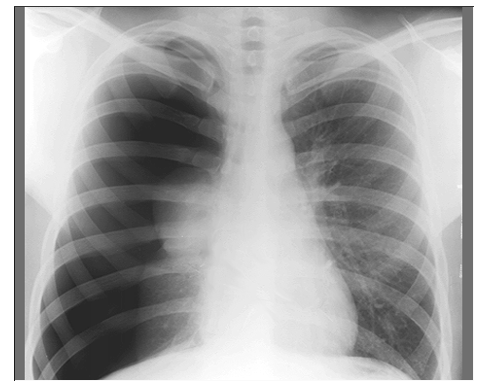
Greater film density on right side of patient. Patient has pneumothorax on right.
Tissue density is the compactness of molecules in atomic structure of different body parts.
Density
Factors Affecting Image Density
mAs –
Directly proportional to density (↑ mAs = ↑ density)
kVp –
Small increase → large increase in density
Distance (TID/SID) –
Greater distance → fewer photons reach the imager → lower density
Distance and How it Affects Density
The distance between the focal spot (target/source) of the x-ray tube and the recording medium.
TID: Target to Imager Distance
FFD: Focal Film Distance
SID: Source to Imager Distance
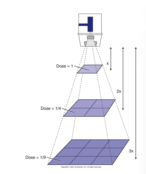
Distance and density relationship follows the inverse square law.
Inverse Square Law
Intensity of the beam inversely proportional to the square of the distance
If distance doubles, the quantity of x-rays reaching the image receptor is reduced to ¼
This is due to the surface area being 4x as great
Intensity is ¼ it’s original value
Contrast
The tonal range of densities from black to white
or the number of shades of gray in an image
It provides visual evidence of the different absorption rates of various body tissues*
kVp & Contrast
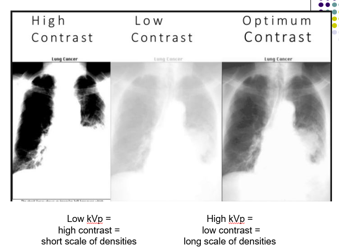
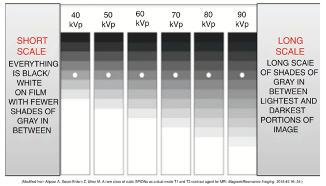
low kVp = high contrast = short scale of contrast (small range of densities)
high kVp = low contrast = long scale of contrast (wide range of densities)
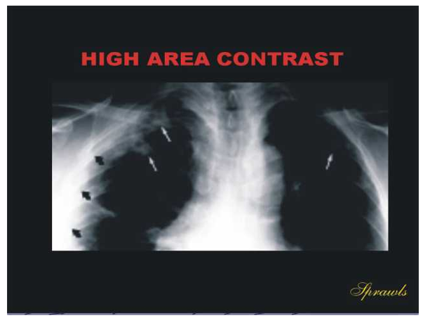
I.e. Images with different contrast levels
Short and long scales of image contrast
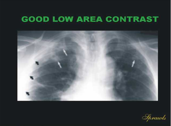
Parts of the body with low contrast between its body parts will give us a better image
Image with high contrast is not desirable.
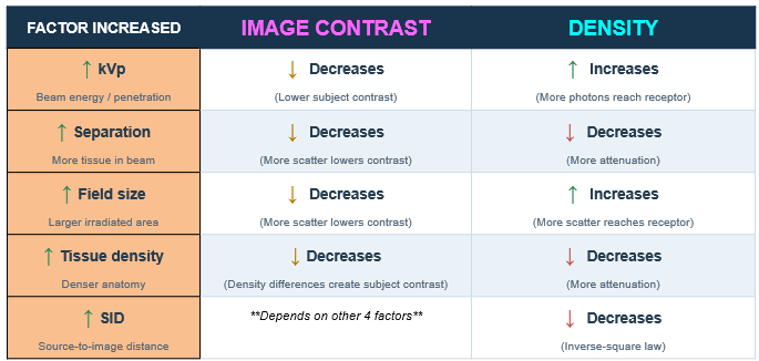
The factors that need to be considered when deciding kVp are: part thickness, scatter radiation, and field size
Structure absorption
Dense structures absorb more photons photoelectrically and produce more Compton scattering
→
Less dense structures - Tissues that are thin or aged - result in decreased attenuation and produce a disproportionately darker image
Older bones with less calcium have less x-ray absorption
Structure Absorption
The amount of energy absorbed by a structure depends on:
the atomic number (Z) of the tissues of that structure,
the mass density of the tissue
the energy of the incident photon
Absorption increases as
Z # increases
Mass Density increases
A material that is twice as dense as another will absorb twice as much energy from the same photon beam
Photon Energy decreases
Low energy photons are more readily absorbed in a material such as biologic tissue than are high-energy photons
Imaging Pathology
Pathology may affect the body’s absorption characteristics
Additive pathology
Adds physical density to body tissues
Examples: Edema, Paget’s disease, atelectasis, abscesses, pleural effusions
Destructive pathology
Lowers the body’s normal attenuation ability
Examples: Astrocytomas, necrotic areas, osteolytic metastatic disease, multiple myeloma
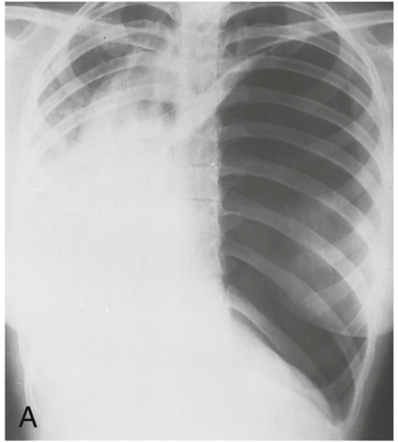
Additive Pathology
This pleural effusion (A pleural effusion is a buildup of fluid between the layers of tissue that line the lungs and chest cavity.) in the left hemithorax is an example of an additive pathology.
Pleural effusion can result in diminished breathing capacity and possible lung collapse.
Additive pathology
Malignant mass in lung
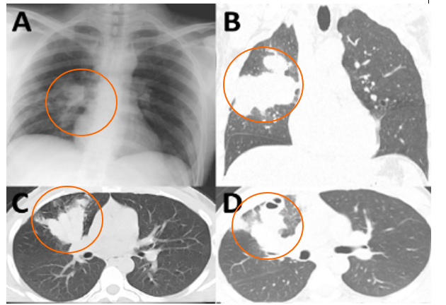
Destructive Pathology
An Ewing sarcoma has destroyed part of the distal femur.

Recording Medias
A medium is a source that may convey data or information
Media is the plural form of many different types of mediums
There are many different types of recording medias
Processing film (older conventional method)
Fluoroscopic screens
Image intensifiers
Electronic imaging devices (EPID)
Photostimulate phosphor plates,
Scintillation and piezoelectric crystals
Flat panel detectors (FPDs)
Digitally reconstructed radiograph (DRR)
Radiographic cassettes
Provides light tight conditions necessary for photostimulable plate or x-ray film to work
Construction:
Front made of a material with a low atomic number
Cardboard
Plastic
Carbon fiber
Back made of the material with a high atomic number
lead
copper
other metal
This is to prevent backscatter from reaching the film once it exits the cassette
Backscatter can cause unnecessary fog and reduce image quality

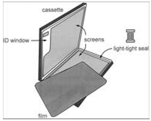
Radiographic cassette
Opens like a book, can only open cassette in a dark room for processing
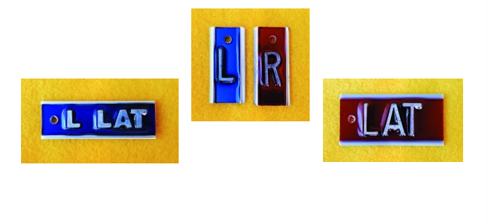
Film markers
used for site identification on films
Computed Radiograph - CR cassette
Photostimulable plates that converts x-rays into a digital image
The plate is known as an imaging plate, storage phosphor plate or digital cassette
A cassette similar to a regular cassette houses the digital imaging plate
Flat Panel Detectors (FPDs)
An amorphous silicon imaging device attached to the linear accelerator
KV & MV Imaging Systems (many linacs have both)
Consists of:
FPD hardware
Workstation
Imaging software
Converts the radiation beam exiting the patient to an electrical signal pixel by pixel to create an image
Benefits of Flat Panel Detectors (FPDs)
Allows real time electronic imaging
Can be acquired in seconds, uploaded to a computer and sent to the MD to review
Is accessible to multiple workstations simultaneously, MD can review from anywhere
Imaging characteristics can be manipulated via software to improve image quality (density, contrast via window leveling)
Images can be archived and integrated in the patient’s electronic record
EPID- Electronic Portal Imaging Device
MV Imaging System
A digital image taken with the therapy machine (MV)
It is better quality than the analog images acquired by using a film and cassette
EPIDs are mounted on linear accelerators to capture images using the treatment beam itself (4–25 MV photons).

OBI – On Board Imaging System
KV Imaging System
A separate kilovoltage X-ray tube mounted on the gantry, opposite a kV flat panel detector.
Completely independent from the MV treatment beam and EPID.
Optimized for 40–150 kVp photons
Uses:
2D kV radiographs (orthogonal pairs for patient setup)
kV fluoroscopy (real-time tumor or fiducial tracking)
kV cone-beam CT (volumetric imaging before treatment)

Thin-film transistor (TFT) technology in Flat Panel Detector technology
TFT acts as switches turning each pixel on (light) or off (dark) depending on the amount of radiation reaching the pixel
A pixel (short for picture element) is a single point in a picture. On the monitor of a computer, a pixel is usually a square. Every pixel has a color and all the pixels together are the picture.
More about this in the CT lectures
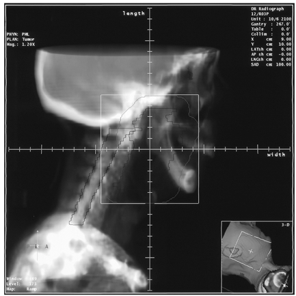
DRR – Digitally Reconstructed Radiograph
An 2D image reconstructed from CT data to create a beam’s-eye-view (BEV) display of the treatment field
These images resemble conventional radiographs
Which structures absorb more photons – more dense tissues or less dense?
More dense tissues absorb more photons
Why?
There are more atoms in that tissue for photons to interact
What x-ray interaction is where the photon is absorbed by the atom?
Photoelectric effect
Which imaging system on the treatment machine using MV energy?
EPID – electronic portal imaging device
What are the two major components of an x-ray tube?
Which is the negatively charged side?
Cathode and anode
Cathode
What is the primary way to control scatter radiation?
Collumation
What happens to the intensity of the beam when distance is doubles?
What is the law that explains this relationship?
It reduces by ¼
Inverse square law
What is the historical unit for exposure in air?
What year did Wilhelm Conrad Roentgen create x-rays
Roentgen
1895