MCQs Principles of Comm
 Call Kai
 Learn
Learn Practice Test
 Spaced Repetition
 Match
Match Flashcards
 Knowt Play
1/129

There's no tags or description
Looks like no tags are added yet.
Name | Mastery | Learn | Test | Matching | Spaced | Call with Kai | Chat |
|---|
No analytics yet
Send a link to your students to track their progress
130 Terms

Why is the first stage of a multi-stage cascaded receiver the primary determinant of the system's overall Noise Factor according to Friis' formula?

What primary physical mechanism generates shot noise in p-n junction diodes and bipolar junction transistors?

In a low-frequency amplifier circuit, what spectral characteristic uniquely identifies flicker (1/f) noise?

Which noise model assumes a constant Power Spectral Density (No/2) across all frequencies from negative to positive infinity?

According to Information Theory, when is the entropy H(X) of a discrete memoryless source with N possible symbols maximized?

If a memoryless channel transmits binary symbols at (1000 symbols/sec), and symbol '0' occurs with probability 1, what is the information rate R of the source?

According to the Hartley-Shannon theorem, if channel bandwidth B is doubled while signal power S and noise spectral density No remain fixed, what happens to channel capacity C?

What fundamental limit does the Shannon Capacity bound represent for a communication channel?
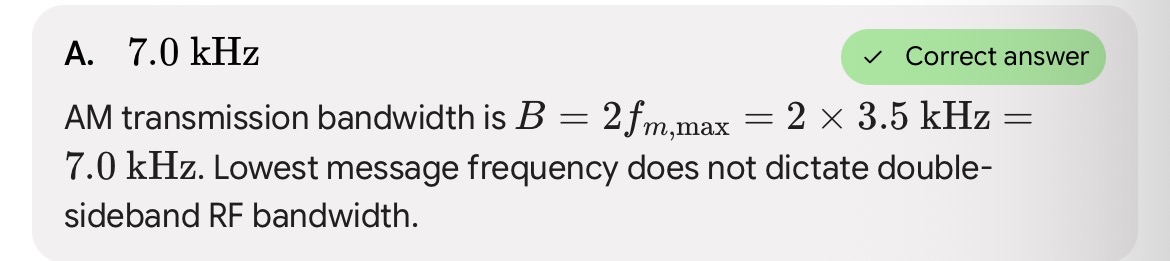
What is the minimum transmission bandwidth required for an AM signal carrying audio speech signals with frequencies ranging from 300Hz to 3.5kHz?


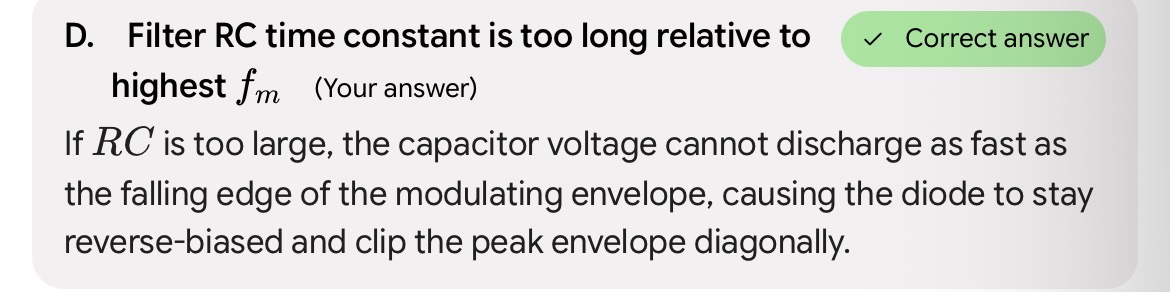
What primary condition leads to diagonal peak clipping distortion in an AM diode envelope detector circuit?

To completely avoid diagonal clipping in a diode envelope detector for a given modulation index m and modulating frequency w, what condition must RC satisfy?

What operational failure occurs in a synchronous (coherent) demodulator if the local oscillator signal has a 90 degree phase error relative to the incoming carrier?

How does a standard diode ring modulator eliminate both carrier and modulating frequencies from its output terminals?

In a Low-Level AM transmitter system, where does amplitude modulation take place in the transmitter chain?

Why must power amplifiers following a Low-Level AM modulator stage be operated strictly in linear classes (Class A, AB, or B)?

What is the primary operational advantage of Single Sideband Suppressed Carrier (SSB-SC) modulation compared to standard AM (DSBFC)?

What is the primary operational advantage of Single Sideband Suppressed Carrier (SSB-SC) modulation compared to standard AM (DSBFC)?

What critical functional block is used in the Phase-Shift method of SSB generation to shift message components by 90 degree across baseband frequencies?

Why is Vestigial Sideband (VSB) modulation used for commercial broadcast analog television signals instead of full SSB?

In a diode envelope detector, what is the role of the high-pass filter (coupling capacitor and resistor) following the envelope filter load?

What system performance metric degrades when negative peak clipping occurs in an AM detector circuit?

What logarithmic unit measures information content when base-e (natural logarithms) are used in entropy calculations?

An ideal noise-free communication channel has 10kHz bandwidth. What is the maximum symbol rate achievable without intersymbol interference according to Nyquist?

What is the primary power advantage of High-Level Modulation over Low-Level Modulation in commercial broadcast AM transmitters?

Which analog AM detector circuit uses a local oscillator synchronized in frequency and phase with the incoming carrier to recover message signals without distortion?

What is the primary function of a balanced modulator circuit in an SSB or DSB-SC transmitter system?
Another way to generate the product of the carrier and Modulating signal Is to apply both signals to a non-linear component or circuit ideally one that generates a square law function.
AM in the frequency domain
Circuit in which the current is not directly proportional to the voltage.
Nonlinear circuit
Components with PN junctions like Diodes and Transistors
Non-linear components
i = av + bv²
Current equation of AM in the frequency domain
av
Linear component of i = av + bv². It is also the applied voltage multiplied by coefficient a usually a dc bias.
bv²
Second order or square-law component of current of AM in frequency domain.

Equation of AM in frequency domain. T
There are a lot of signal components but only the carrier, upper and lower side band components are needed (encircled terms)
A LC circuit at resonant is placed
Diode passes only the positive half-cycle
At the + half cycle: capacitor charges
At the - half cycle: capacitor discharges through the inductor.
To filter the AM signal in the frequency domain to get only the necessary components, this is the circuit to be used.

Diode Modulator in Low-Level AM

Transistor Modulator Low-Level AM

Differential Amplifier Modulator Low-Level AM

Amplification of Low-Level AM signal

Collector Modulator in High-Level AM

Series Modulator in High-Level AM

Diode detector for AM demodulator

DSBSC Balanced modulator
Gets the product of 2 input signals (carrier and modulating)
Balanced modulator or product modulator

DSBSC equation derivation

DSBSC final equation

Another formula for % power saving for DSBSC

Total power of DSBSC
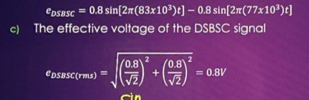
Vrms of DSBSC using it’s non-ideal equation resulting from the nonlinear modulator

Power of DSBSC using the non-ideal equation resulting from the nonlinear modulator
Filter Method
Phase Shift / Phase Cancellation method
“Third” Method (combination of 1 and 2)
3 ways of suppressing the unwanted side and in the SSBSC
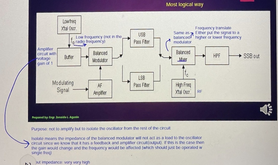
SSBSC Filter Method

Output of Balanced Modulator

SSBSC Phase Shift Method

cosAcosB identity

SSBSC “Third” Method
this method filter at high frequencies because the past band of the filter becomes very wide. Thus, the frequency response curve is wide, and this might lead to failure in removing the unwanted sideband.
Filter method disadvantage For SSBSC
This method results in failure, if the amplitude and frequency is not the same in the opposite polarity.
Phase shift method disadvantage of SSBSC
this is simple to implement
This can be the modulated using a circuit consisting of very few components
A.m. receivers are very cheap as no specialized components are needed
Advantages of amplitude modulation or AM
It is not efficient in terms of power usage
It is not efficient in terms of its use of bandwidth requiring a bandwidth equal to twice of the highest audio frequency
It is prone to high levels of noise because most noise is amplitude based and AM detectors are sensitive to it
Disadvantages of AM

Equation of FM with carrier: cos, modulating: cos


Equation of FM with carrier: -cos, modulating: - sin

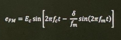
Equation of FM with carrier: sin, modulating: - cos


Equation of FM with carrier: sin, modulating: sin
that specific sideband gets insignificant which can be removed so that the BW can be approximated
As the amplitude of the FM sideband is getting smaller, then?
Infinite BW
FM sign, has infinite sidedband means it has?

Frequency Spectrum of FM
This says that sideband is considered insignificant if its amplitude is less than 1% of the carrier amplitude
Bessel’s Bandwidth Approximation
This says that sideband is considered insignificant if it’s amplitude is less than 5% of the carrier amplitude
Carson’s Bandwidth Approximation

Only dependent on the rms values of the carrier characteristics
Effective voltage, effective current and power of FM signal
worst case modulation index
Used when modulating signal is complex signal (not a sinusoid)
Deviation Ratio, DR

FM modulator

Output of FM demodulator
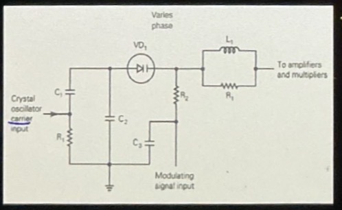
PM Modulator

Output of PM modulator

Slope Detector - FM demodulator
Since the frequency of the FM signal is changing, if the amplitude is not of the frequency of oscillation, it will attenuate signal. Thus designed the LC circuit, such that it has a frequency of oscillation that is greater than the carrier frequency where it would operate in the linear portion so that the amount of increase in frequency would introduce the same amount of attenuation with the same slope. This straight line would only be a small portion (a disadvantage) that’s why the FM signal should only have a small frequency deviation..
In FM demodulation, how can FM be converted to AM for the slope detector?
There is additive noise but can be cleaned using a clipper/limiter
Disadvantage of slope detector

Balanced Slope detector- FM demodulator
simpler circuit
Poor linearity or difficult to tune
Need to use separate limited stage to compensate amplitude variation
Slope detector characteristics
more complex circuit
Better linearity and tuning
Does not need limiter stage
Balanced slope demodulator characteristics

Phase Lock Loop FM Detector
This means that as the noise amplitude increases, then the peak also increases. As the modulating signal increases, the phase deviation also increases. Thus, this means that as the noise increases, there is also an increase in phase deviation
What does the unwanted peak phase deviation due to interfering noise signal in phase modulation mean?
The highest frequency that would affect the information is equal to the highest frequency of the modulating signal. Thus, as the frequency of the noise increases, then there is also an increase in the frequency deviation
What does the unwanted peak frequency deviation in frequency modulation mean?
The ratio of signal to noise is not the same for higher and lower frequency. The signal is better at lower frequencies. The solution is to have the amplitude of your signal be lower at the low frequencies compared to higher frequencies.
Purpose of pre-emphasis and de-emphasis
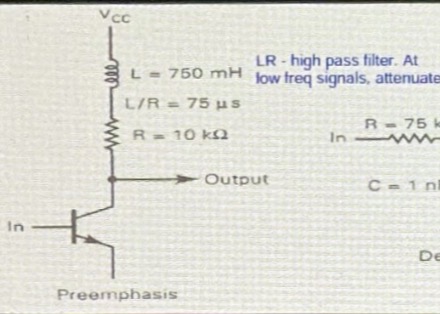
LC circuit
Pre-emphasis circuit

RC circuit
De-emphasis circuit

Cut-off frequency of pre-emphasis circuit

Cut-off frequency of de-emphasis circuit
noise immunity
Noise performance and S/N ratio improvement
CAPTURE EFFECT
Power utilizations and deficiency since the total power is all used
Advantages of angle modulation
Once there is a signal of the same carrier than the capture of signals would be interfering
Capture effect in amplitude modulation
For two signals of the same carrier, only one is the modulated which is the stronger signal
Capture effect of frequency modulated signals
wide bandwidth or it has many side bands
It Has complex circuit and high cost
Disadvantages of angle modulation
This is a conventional radio receiver, which converts the modulated waveform back to the original form by receiving, amplifying and demodulating the wave. the receiver also functions to band limit the total RF spectrum to a specific desired band of frequency, which tunes the receiver.
Radio receiver
This is a parameter used to measure the ability of the receiver to accept given band of frequencies and reject all others
Selectivity
This is a parameter used to measure the ability of the receiver to detect, weak signals, and still produce a usable demodulated information signal. it is expressed in microvolts or microwatts.
Sensitivity

Tuned radio frequency receiver
Too much the impotence of antenna and the amplifier
Purpose of antenna coupling network in the tune radio frequency receiver

This is to increase the sensitivity of the receiver, which is introduced by having a high gain. Each stage is tuned to the same frequency through the gang capacitors.
At the same amplitudes, The first filter would attenuate the signal that are not at the maximum amplitude. the second and third would attenuate it again leading to a narrower bandwidth.
The purpose of cascade amplifiers in the tune radio receiver
The bandwidth is inconsistent and varies with the center frequency when tuned over a wide range of input frequencies.
As the frequency increases the filter bandwidth (BW = fr/Q) Increases. Thus, The selectivity of the input filter changes over an appreciable range of input frequencies.
As the LC design filter increases in resonant frequency, then the bandwidth also increases
Adding several more LLC filters, it can become narrower, but at small residential frequencies it would be too narrow.
The disadvantages of the tune radio frequency receiver