Dental Radiology
1/56
There's no tags or description
Looks like no tags are added yet.
Name | Mastery | Learn | Test | Matching | Spaced | Call with Kai |
|---|
No analytics yet
Send a link to your students to track their progress
57 Terms
Parallel Technique
1) Long axis of tooth and film are parallel to eachother
2) The central ray is directed perpendicular to the long axis of the tooth and film
Periapical Film
Used to show root apex of tooth and surrounding structures
Bitewing exposure
Used to detect interproximal decay and height of alveolar bone
Occlusial
Used to view cross section of the teeth and complete palatal structure or floor of mouth
5 safety precautions for operator
1) Never hold film in patients mouth
2) Stand behind a protective barrier
3) stand 6 feet away from x-ray unit
4)Never stand in direct line of primary beam
5) Use lead lined open cone
Care of x-ray unit
1) Don't force unit arm to be extended
2) Don't leave the arm extended after use
3) allow 5 seconds between exposures to let the tube cool
4) Don't let the tube head hit the wall
5) always turn off unit when finished
Inverse Square Law
Using a longer target object diminishes intensity of radiation
Horizontal angulation (Parallel Technique)
Central ray must pass through the teeth parallel to the proximal surfaces
Vertical Angulation (Parallel Technique)
The film is parallel to the long axis of the teeth
Elongation
Vertical angulation too low
Foreshortening
Vertical angulation too high
Overlapping
Result of incorrect horizontal angualtion
Target Film Distance
16"
Full Mouth Series
Anterior- 8
Posterior-8
Bitewing-4
Maxillary Anterior Films
Maxillary Right Cuspid
Maxillary Right Lateral
Maxillary Centrals
Maxillary Left Lateral
Maxillary Left Cuspid
Mandibular Anterior Films
Mandibular Right Cuspid
Mandibular Lateral central incisors
Mandibular left cuspid
Posterior Maxillary Films
Right molar
Right Bicuspid
Left bicuspid
Left molar
Posterior Mandibular Films
Right Molar
Right Bicuspid
Left Bicuspid
Left Molar
Bitewings
Right Molar
Right bicuspid
left bicuspid
left molar
Anatomical Landmarks
Those normal structures and areas which appear in a routine series of radiographs
Radiolucent
Black; dark gray
Radiopaque
White; light gray
Enamel
Most dense structure in human body; radiopaque; can see
Dentin
Internal portion of tooth; radiopaque; less dense than enamel; cannot see
Cementium
Cannot see; less dense than dentin
Pulp
Radiolucent; can see; composed of nerves and blood vessels
Cortical Bone
Radiopaque; immediately surrounds and supports teeth.
Cancellanious Bone
Appears less radiopaque than cortical bone; less dense
Alveolar Bone
Radiopaque; composed of cortical and cancellanious bone; part of bone where tooth eruption occurs
Periodontal Ligament
Radiolucent line; between tooth and cortical bone (lamina dura)
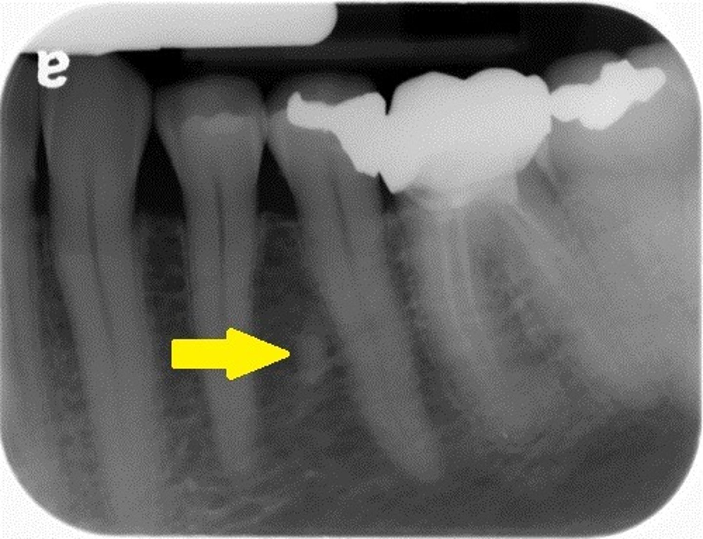
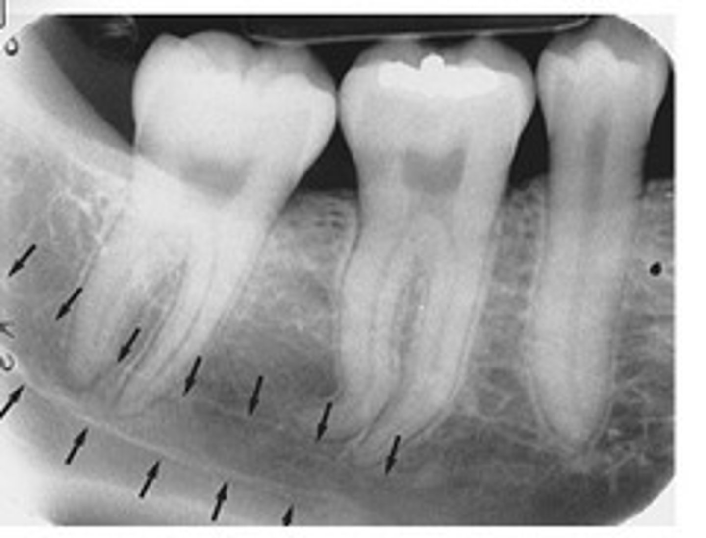
Nutrient Canals
Radiolucent lines in bone; contains blood vessels and exhibit radiopaque borders
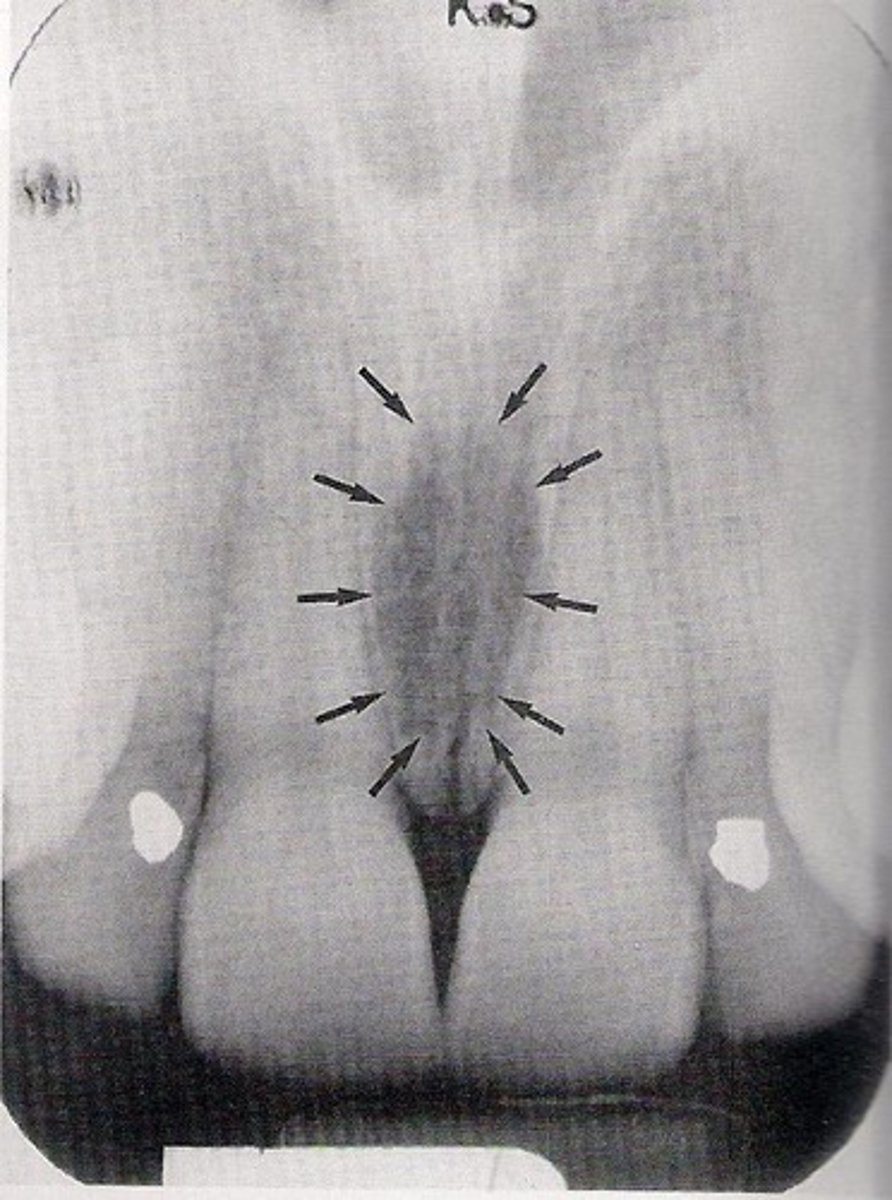
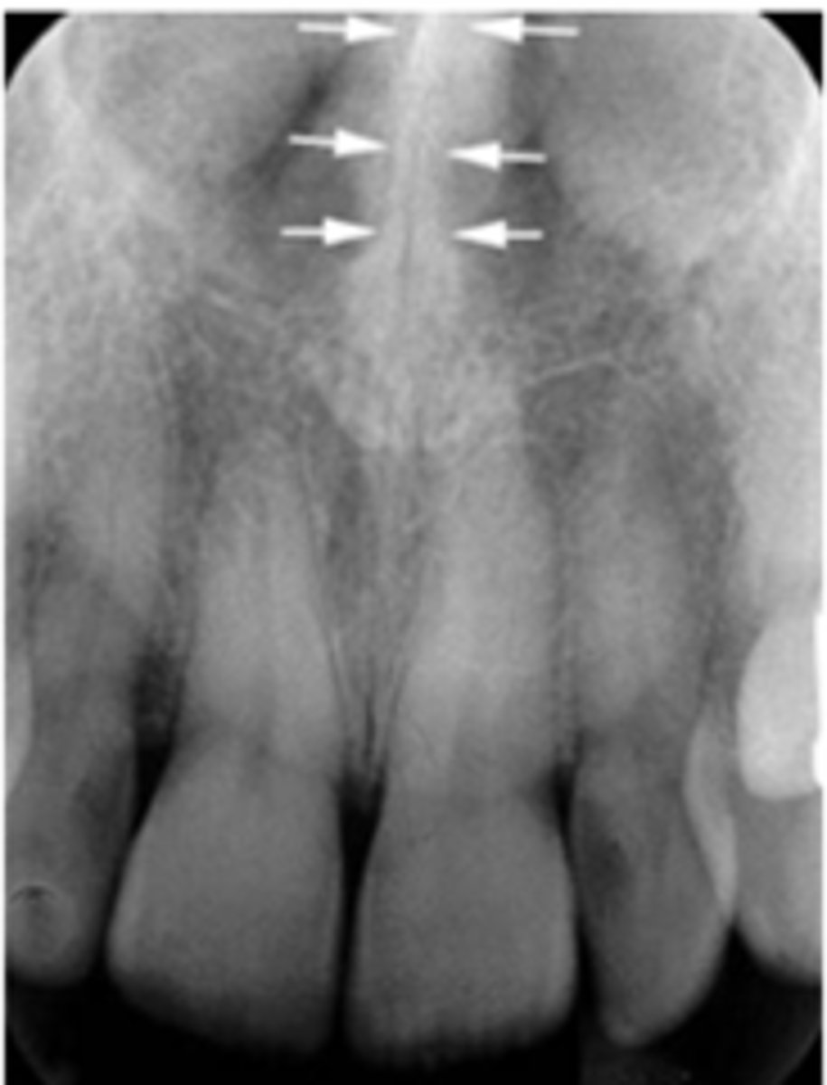
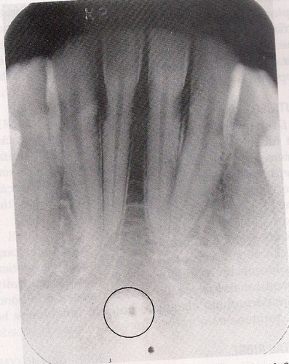
Incisive Canal Foramen/ Anterior Palatine Foramen
Radiolucent; Oval shaped between the apices of the central incisors
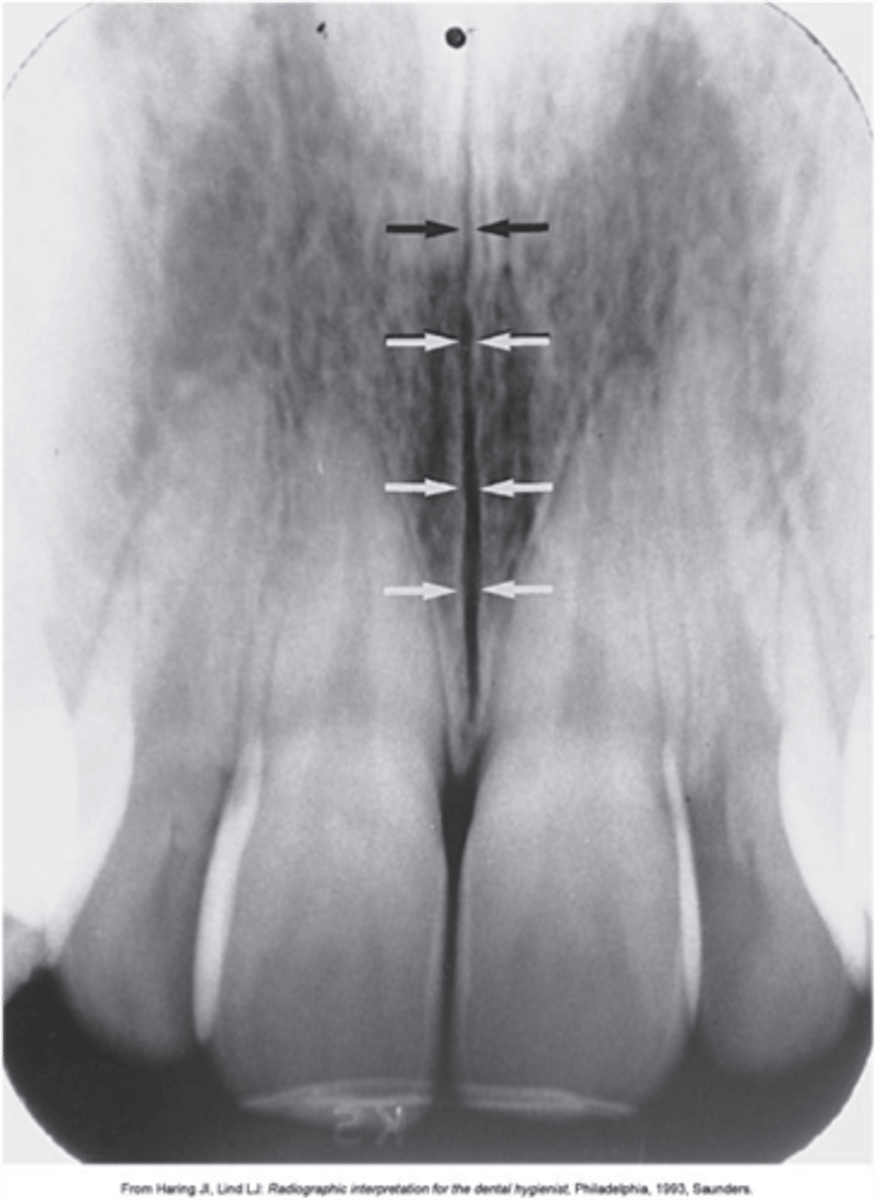
Median Palatine Suture
Radiolucent; extends posteriorly through the midline of the palate
Nasal Fossae
2 radiolucent areas in upper portion of radiograph; air spaces
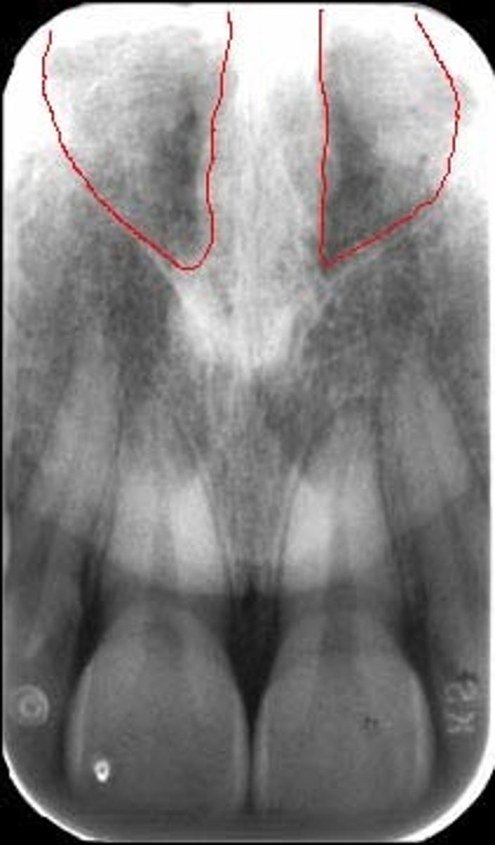
Nasal Septum
radiopaque; between the nasal fossae
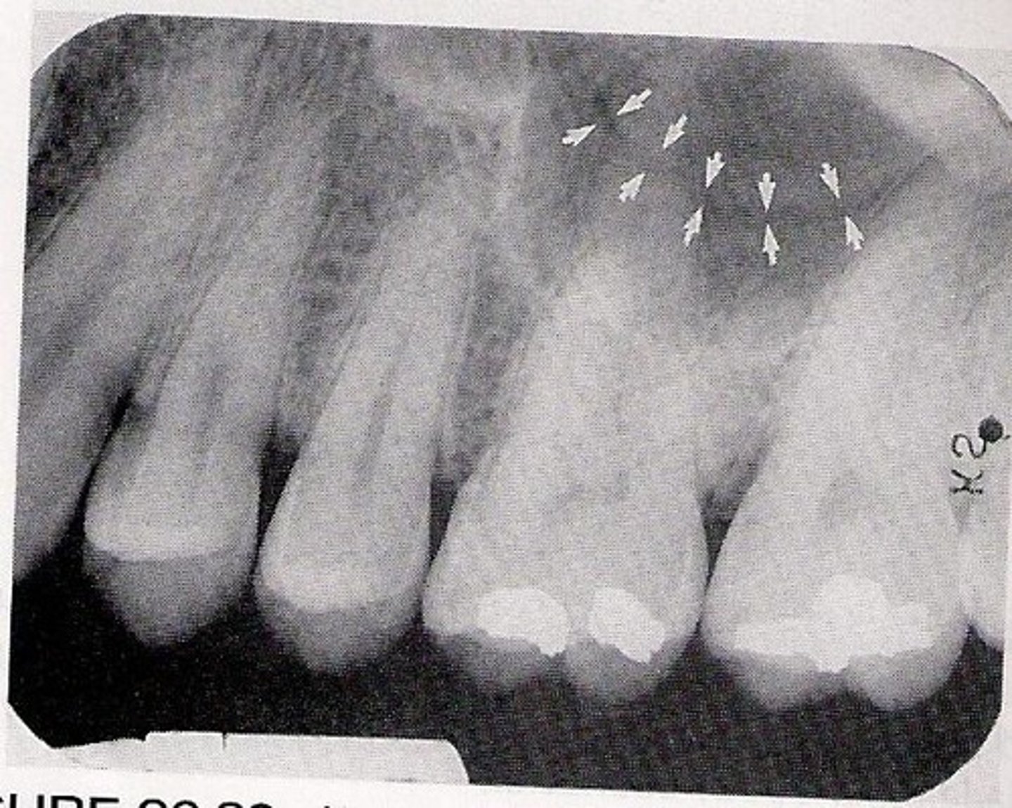
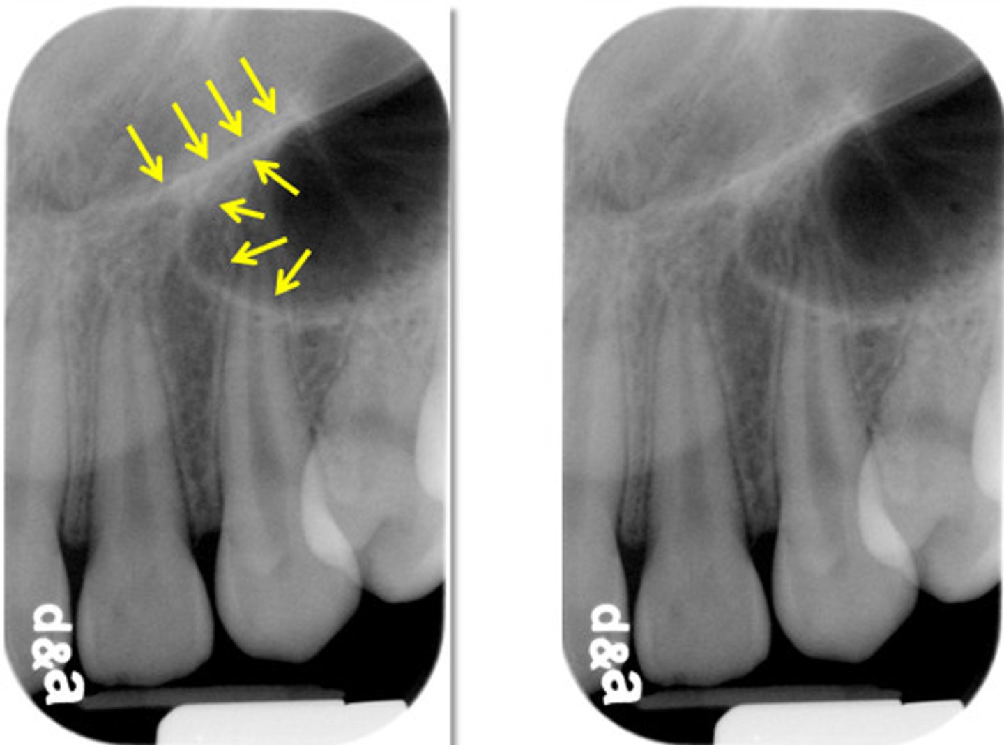
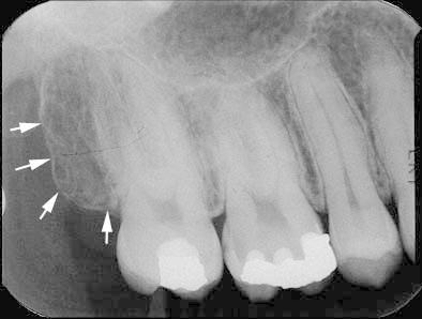
Maxillary Sinus
Airspace above bicuspids
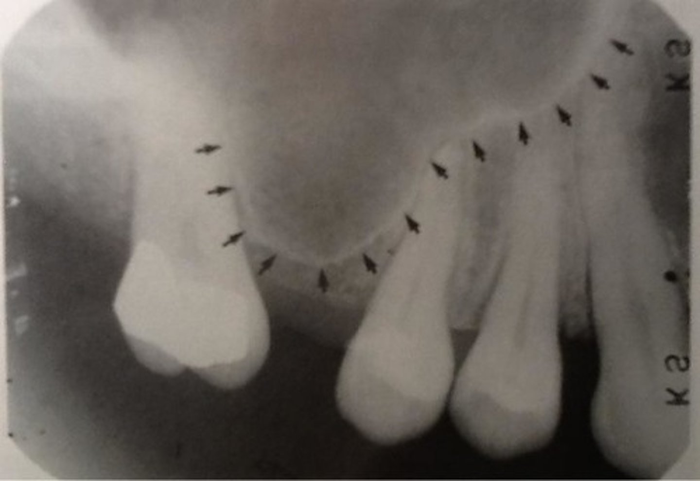
Typical "Y" of maxillary sinus
Radiopaque; where the upper front wall of maxillary sinus joins with floor of nasal fossa
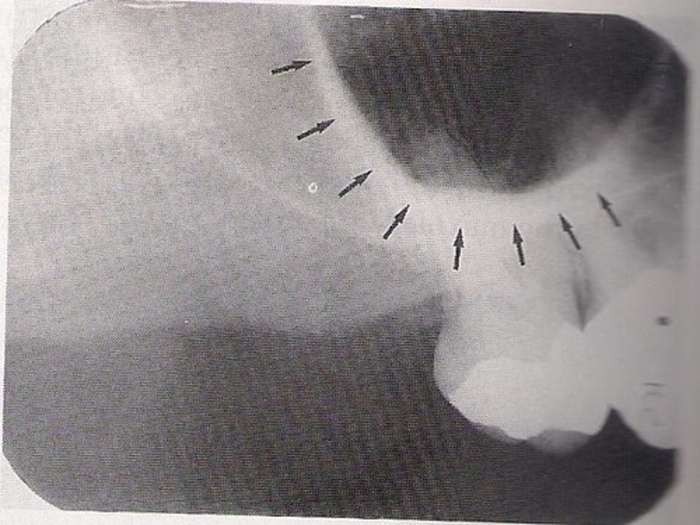
Zygomatic Process
U shaped; in apical region of 1st and 2nd molars
Zygomatic Arch
Superimposed over maxillary molar sinus- radiopaque

Maxillary Tuberosity
Hamular Process
Tenious attachment for muscle fibers
Coronoid Process
Point of muscle attachment
Lingual Foramen
Radiolucent' between apices of mandibular central incisors
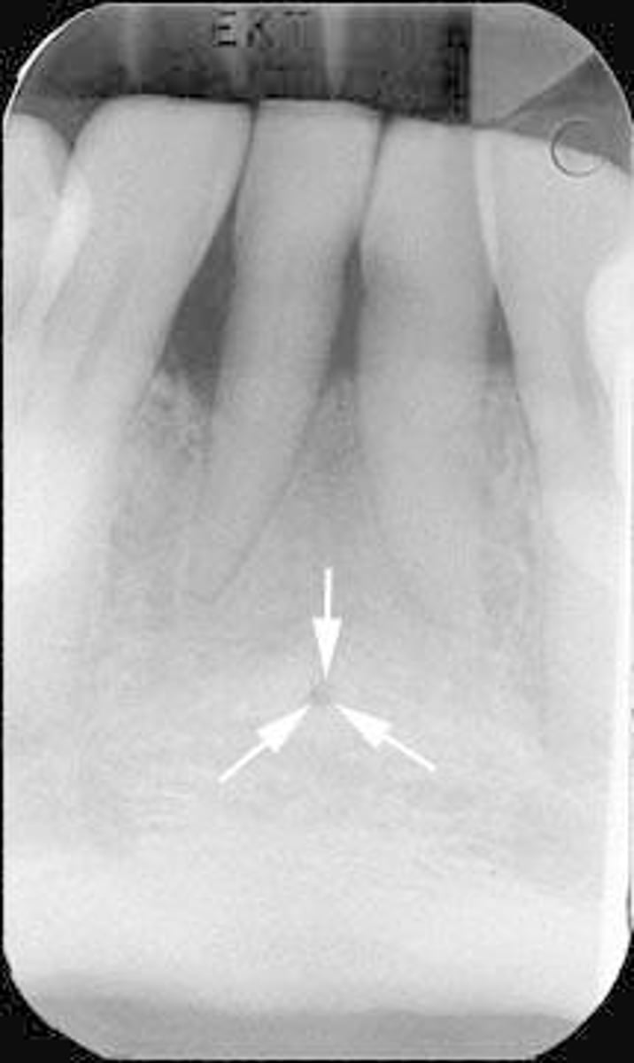
Genial Tubercles
Surrounds lingual foramen
Mental Ridge
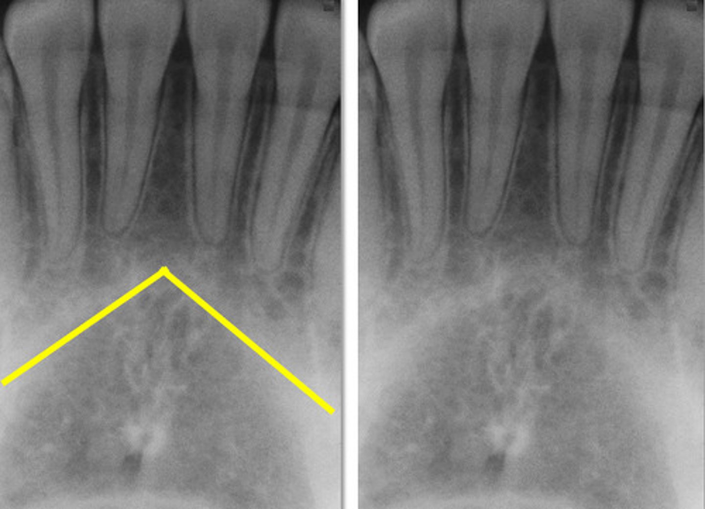
Inferior border of the mandible
Thick radiopaque band
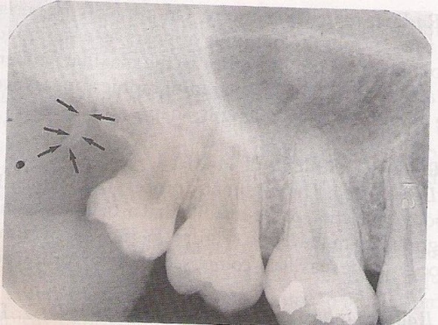
Mental Foramen
Lines inferior to the mandibular apices of bicuspids
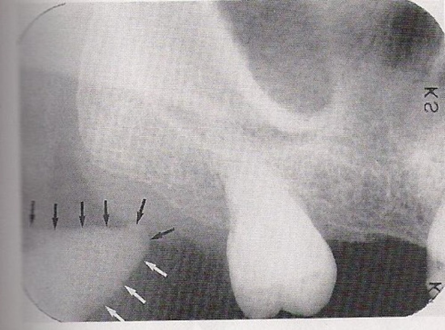
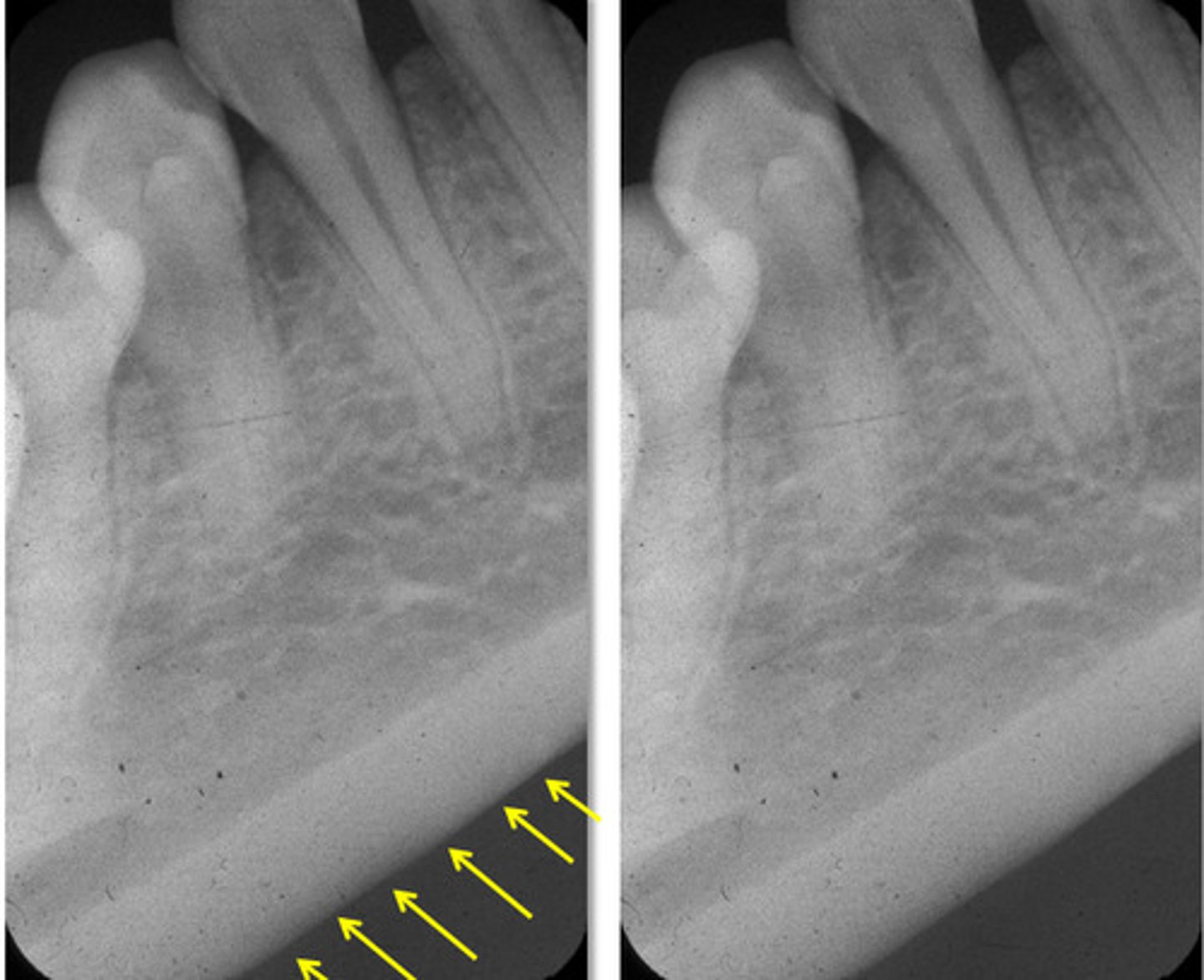
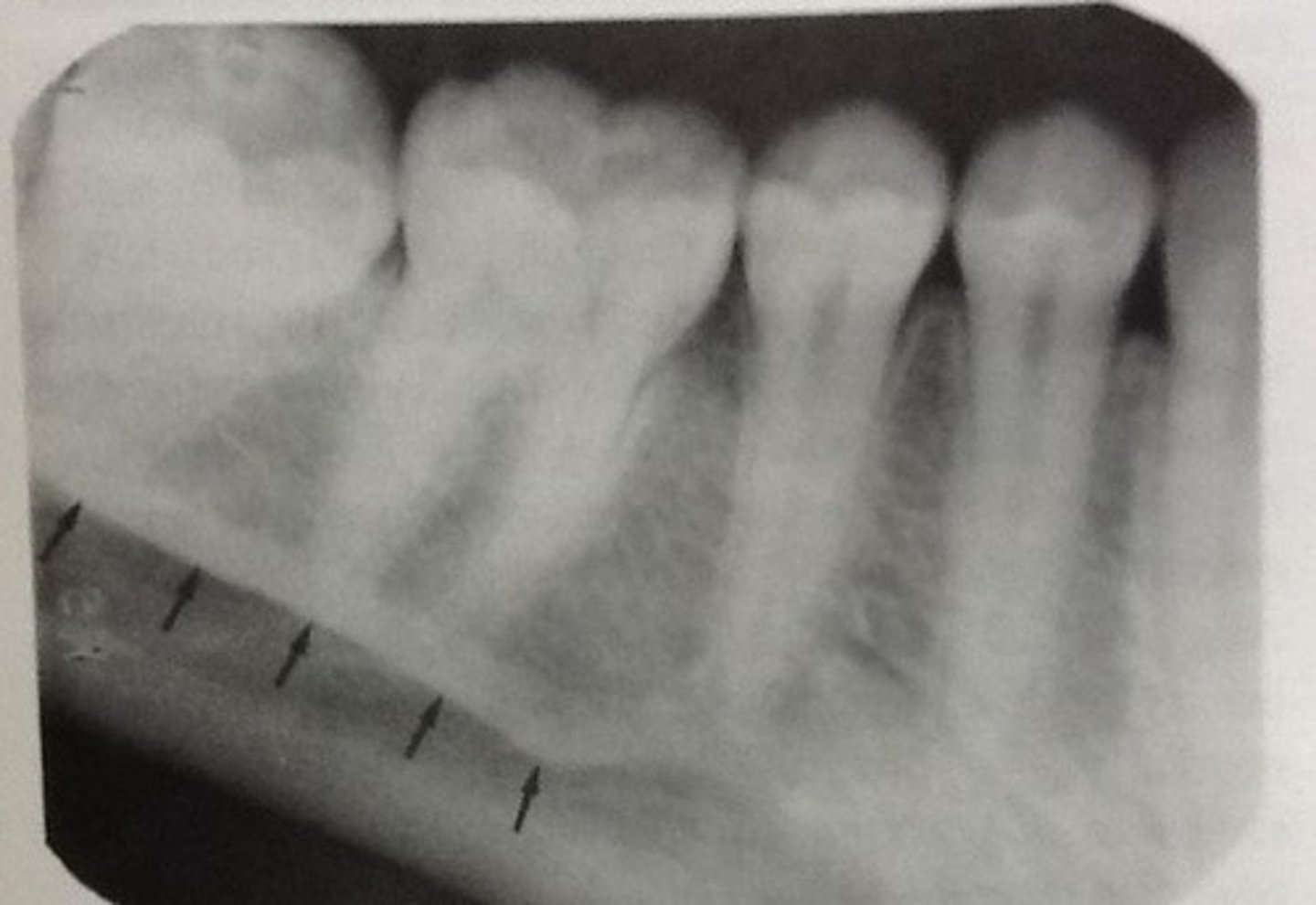
Mylohyoid Ridge
Below apices of the molars
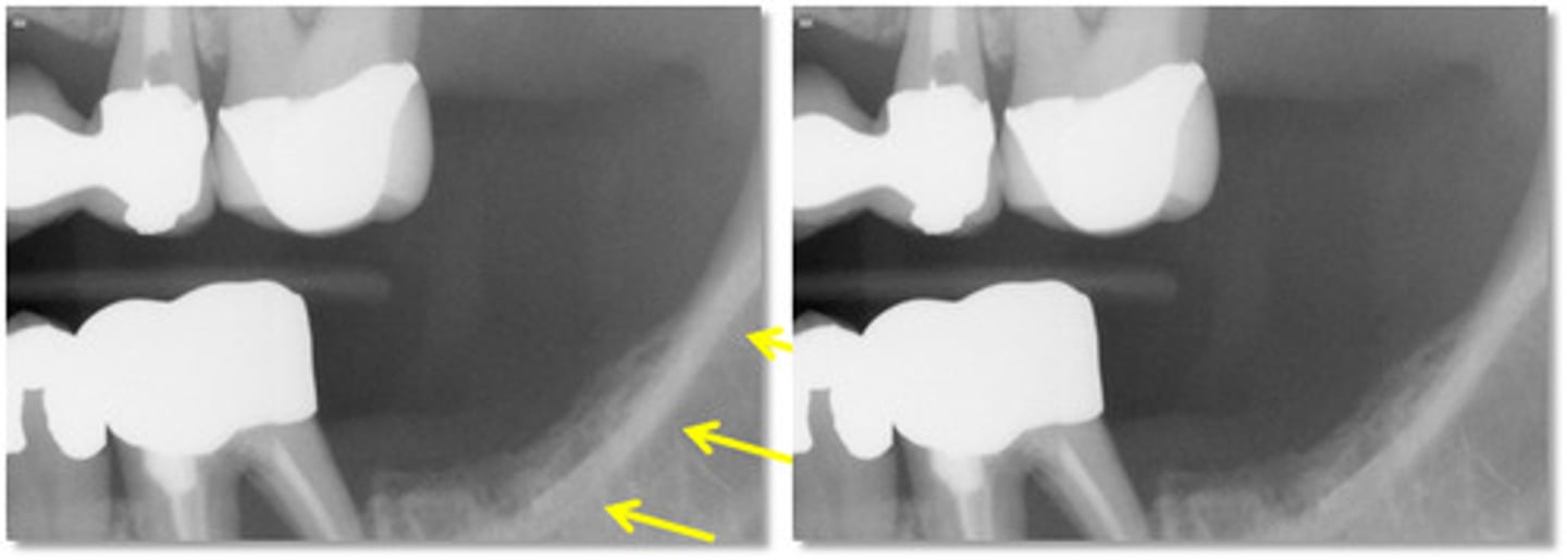
External Oblique Ridge
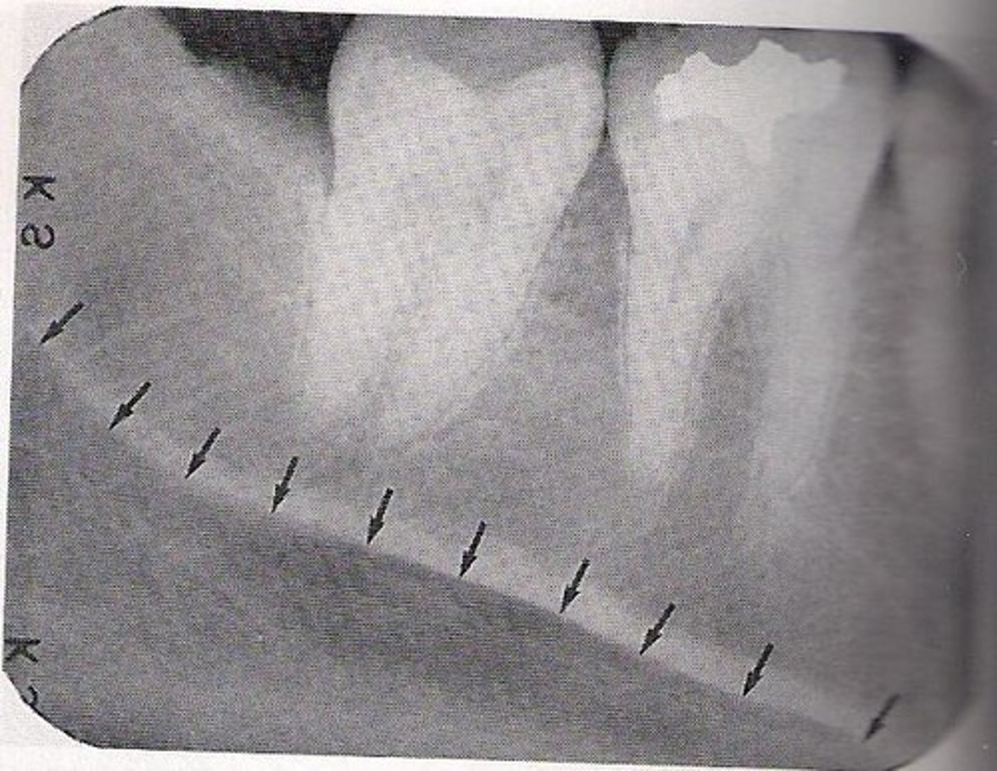
Submandibular Fossa
below roots of mandibular molar
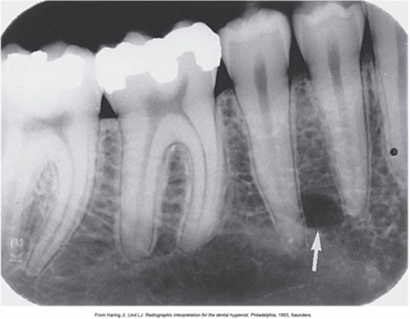
Mandibluar Canal
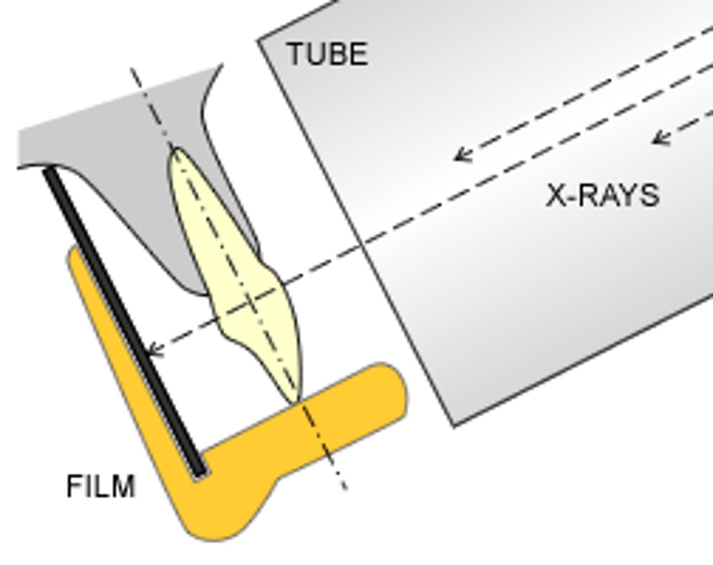
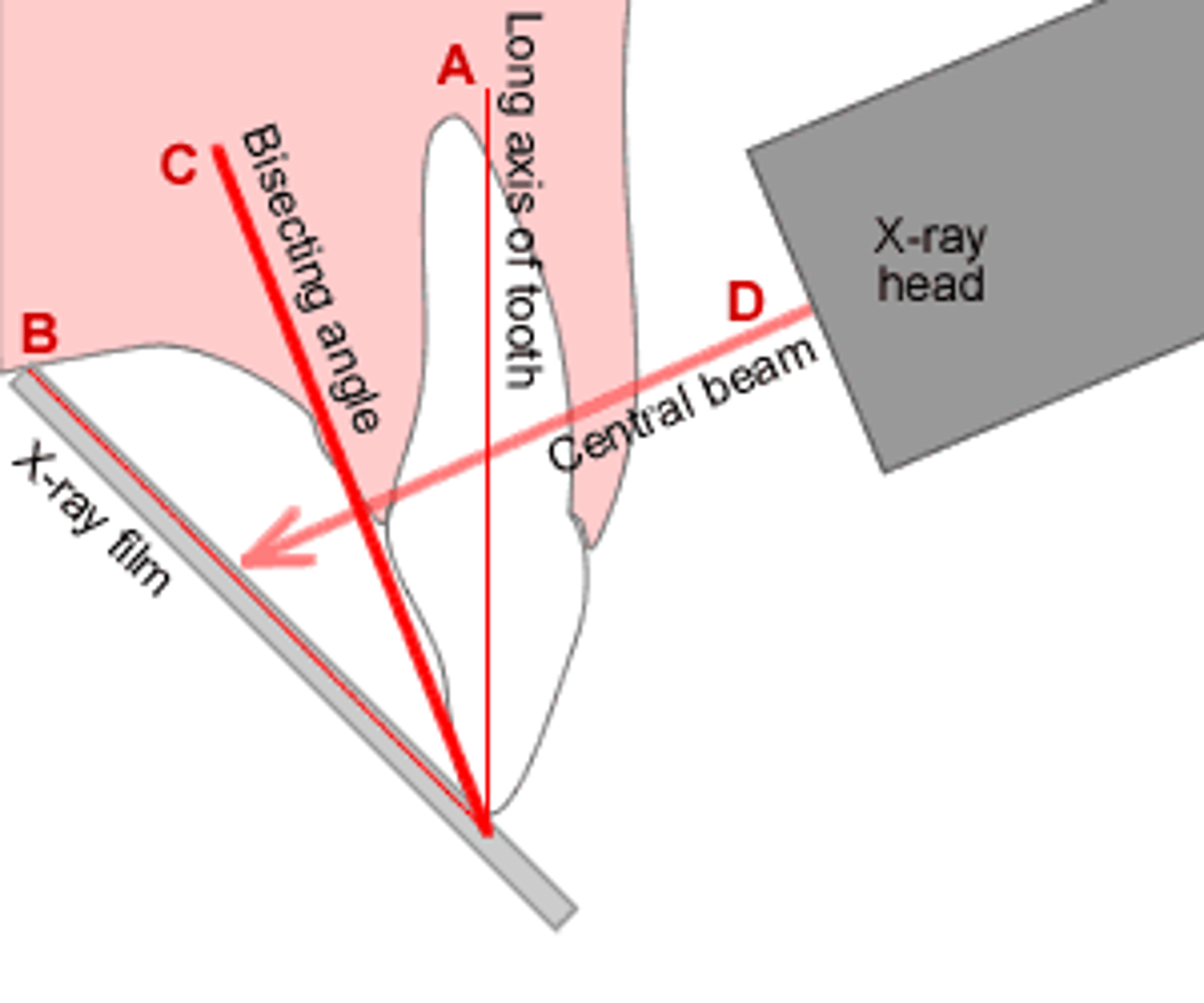
Bisecting Angle Technique
Central Ray is directed perpendicular to an imaginary line which bisects the long axis of the tooth and the film
Least amount of film in FMS
14
7-Max
7-Mand
Vertical Angulation (BAT)
The opening of the cone is vertically parallel to the bisector
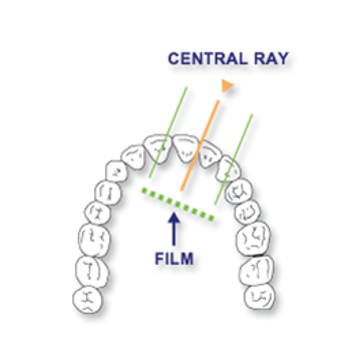
Horizontal Angulation (BAT)
The opening of the cone is horizontally parallel to the angle of the arch of the teeth to be exposed
Cone cut prevention (BAT)
Front and back: Cone is 1/4'' anterior to the film.
Top and bottom: Cone is 1/4'' above (maxillary) or below (mandibular) the occlusial plane.
5 most common errors in technique
foreshortening
elongation
horizontal overlap
cone cutting
excessive bending