Mod 6c Electrical Hardware
 Call Kai
 Learn
Learn Practice Test
 Spaced Repetition
 Match
Match Flashcards
 Knowt Play
1/137

There's no tags or description
Looks like no tags are added yet.
Name | Mastery | Learn | Test | Matching | Spaced | Call with Kai | Chat |
|---|
No analytics yet
Send a link to your students to track their progress
138 Terms
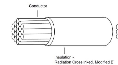
Insulated Wire
provides: dielectric insulation, thermal protection, abrasion resistance, moisture resistance, fire resistance, and fluid resistance.
Conductor Materials
Resistance is directly proportional to length → Longer wire = higher resistance.
Resistance is inversely proportional to cross-sectional area → Larger cross-sectional area = lower resistance.
Copper or Copper Alloy Wire
Non-magnetic – won’t interfere with sensitive flight equipment.
Malleable, conductive, and corrosion resistant.
Smaller cross-sectional area than aluminium (same current rating).
Easier to bend, shape, and terminate.
Aluminium or Aluminium Alloy Wire
Used for high current over long distances.
Non-magnetic.
Higher specific resistance than copper → requires a larger cross-sectional area.
Approximately 50% weight saving compared to copper.
Can crystallise (work-harden) and break under vibration.
Rarely used for general aircraft wiring.
Do not use on engine-mounted accessories or in areas with:
Corrosive fumes
Severe vibration
Mechanical stresses
Frequent disconnection
Conductor Plating
Copper and aluminium oxidise when exposed to oxygen.
Oxidation is accelerated by aircraft temperature and pressure variations.
Plated with tin, silver, or nickel to minimise oxidation.
Wire Size
Measured using the American Wire Gauge (AWG) system.
Larger AWG number = smaller wire.
Typical aircraft wire sizes: 24 AWG (smallest) to 0000 (4/0) AWG (largest).
24 AWG = 0.51 mm, 0000 (4/0) AWG = 11.7 mm.
14 AWG
20 AMPs
12 AWG Stranded & Solid
25 AMPs
10 AWG
30 AMPs
8 AWG
40 AMPs
6 AWG
55 AMPs
2 AWG
95 AMPs
1/0 AWG
125 AMPs
Aircraft Wire Insulation
Materials: PVC, nylon, Teflon®, various polymers, and glass cloth braid.
Most insulation is rated to 600 V.
Wire Insulation Temperature Rating
Insulation does not affect wire resistance.
Resistance generates heat, which can burn the insulation.
Current limit depends on the insulation temperature rating.
Different types of insulation have different temperature ratings.
Insulation Resistance
Resistance to current leakage through the insulation.
Measured with an insulation tester (megger).
Used to determine the condition of insulation.
Cracked or faulty insulation is not serviceable, even if insulation resistance is high.
Electrical Cable
includes:
Two or more insulated conductors in a common insulating material.
One or more insulated conductors with an overall shield (shielded cable).
Two insulated conductors twisted together (twisted pair).
Single insulated centre conductor with a metallic braided outer conductor (coaxial cable).
Aircraft Wire
Only approved aircraft wiring is permitted.
Must pass rigorous testing before being added to the Qualified Products List (QPL).
OEM/military wire must come from approved wire mills.
Majority of aircraft wiring is made from stranded copper.
Conductor Stranding
Stranded wire = smaller wires twisted or wrapped together.
Provides more flexibility than solid conductors.
Reduces metal fatigue.
Reduces conductor breakage caused by flight vibration and flexing.
Bonding
Grounds components not otherwise electrically connected.
Protects against static/electrostatic charge build-up and lightning strike discharge.
Correct bonding:
Minimises electrical damage.
Prevents high potential differences (sparks).
Reduces electric shock risk.
Reduces interference with radio communications and navigational aids.
Provides a low resistance electrical return path in earth-return systems.
Shielding
Current-carrying wires produce a magnetic field.
Magnetic fields can interfere with aircraft instrumentation and control systems.
AC and pulsating DC have the greatest effect on electronic equipment.
Airframe Wire
Designed for component interconnection in the aircraft airframe.
Normal or medium weight wire.
Two insulation coverings for improved abrasion protection.
Can be used without conduit in harsh conditions.
High tensile strength reduces installation damage and breakage.
Airframe Wire Construction
Must have at least 19 conductor strands and be 18 AWG or larger.
Airframe Wire Characteristics
Multiple thick insulation layers for harsh conditions.
Stiff and springy, making installation more difficult.
Corrosion-resistant plated conductors make soldering difficult.
Interconnect/Hook-up Cable
Designed for component interconnection inside the fuselage.
Lightweight with one insulation layer.
Requires secondary insulation/conduit if used as airframe wire.
Smaller diameter than equivalent airframe wire.
More flexible, saving weight and space.
More prone to damage when pulled through pressure bungs.
Interconnect Cable Construction
Must have at least 19 conductor strands.
Small gauge wires: use high-strength alloy conductors.
Wires smaller than 20 AWG:
Additional clamps.
Group with at least 3 other wires.
Additional support at terminations.
Do not use where there is:
Excessive vibration.
Repeated bending.
Frequent disconnection from screw terminations.
Equipment Wire
Used within aircraft equipment (LRUs).
Smaller conductor sizes than hook-up wire.
More strands for flexibility and good solder joints.
Can be single-strand if secured to a solid structure.
Thinner, less springy insulation.
Not designed for interconnect wiring.
Fire Resistant Cable
Used in flight critical circuits.
Resists flames up to 1093 °C (2000 °F) under short-time emergency conditions.
Predominantly used in the engine compartment.
Warning: This Wire May Contain Asbest
Asbestos has not been permitted since 1993.
Undated fire resistant wire should be treated as containing asbestos.
Contact Environmental Health if asbestos is identified or suspected.
Replace with non-asbestos alternatives where feasible.
Fire resistance ≠ high temperature.
Use fire resistant cable only where required.
More susceptible to contamination and abrasion.
Fire Resistant Cable Construction
Multiple insulation layers for fire protection.
Maintains insulation for 30 minutes to allow the aircraft to land.
Conductors have a thick alloy coating with a higher melting point than copper.
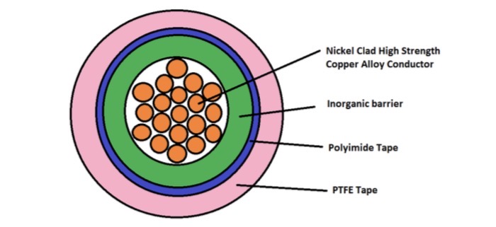
Fire Resistant Cable Construction Diagram
inside → outside
Nickel clad high strength copper alloy conductor – conductor with a high melting point coating.
Inorganic barrier – thermal insulation against fire.
Polyimide tape – maintains electrical insulation at high temperatures.
PTFE tape – outer protective layer (abrasion/chemical protection).
High Temperature Cable
Temperature rating of 125 °C or higher (some manufacturers use 90 °C).
Different from fire-resistant cable.
Can be single- or multi-conductor.
May have a fibreglass braid or Kevlar-fibre jacket.
Two key factors:
Temperature rating – maximum continuous operating temperature.
Current capacity – maximum current without exceeding insulation/jacket temperature limits.
Undersized cable overheats, reducing cable life and compromising the cable.
Thermocouple Cable
Used to detect and measure temperature changes.
Made of a pair of dissimilar metallic conductors.
Extension leads must be the same material as the thermocouple.
Extension wires are paired in a braided jacket and colour coded.
Correct installation is required to maintain accuracy.
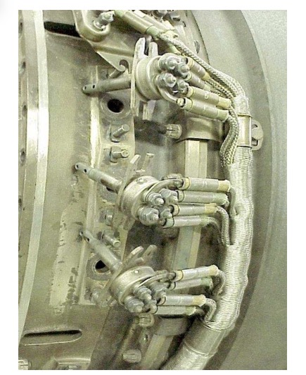
Gas turbine engines use multiple thermocouples arranged in a harness.
Thermocouple Cable Construction
Harness insulation: silicone rubber or PTFE-impregnated fibreglass.
Harness terminates at an engine or firewall junction box.
Extension cable insulation: polyvinyl, as it is not subject to high temperatures.
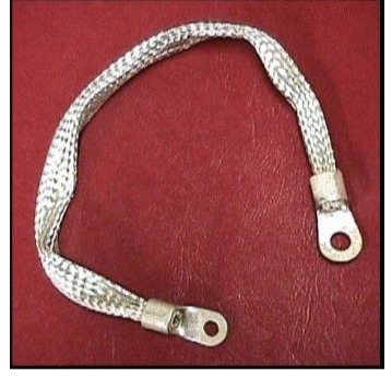
Bonding Lead
Shock Mount with Bonding Strap
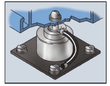
Bonding Cable Construction
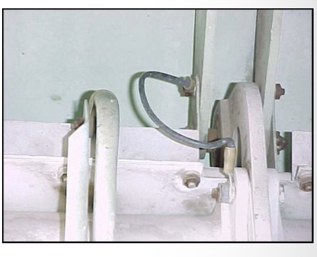
Made from copper or aluminium.
Must have sufficient surge capacity to carry the whole discharge.
Material must not produce galvanic corrosion.
Length: long enough for movement, not so long that resistance increases.
Sacrificial aluminium washers prevent galvanic corrosion between copper straps and aluminium structure.
Aluminium alloy straps are used in most cases.
Copper straps are used to bond stainless steel, cadmium plated steel, copper, brass, or bronze.
Always use the bonding cables/straps specified in the AMM and IPC.
Bonding Strap on a Flight Control
AC 43.13-1B Section 15
Grounding and Bonding
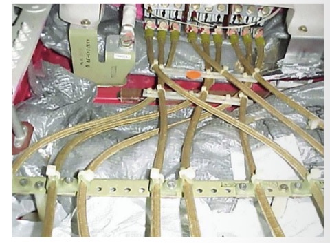
Power Cables
Runs from power sources to bus bars, between bus bars, and from bus bars to equipment.
Protected by circuit protection devices.
Aluminium conductors are ~50% lighter than copper but are usually 2 AWG sizes larger.
Aluminium conductors have more strands to reduce vibration cracking (work hardening).
Copper cables are used between engine-mounted generators and the fuselage.
Generator feeder cables are an example of power cables.
Generator Feeder Cables
Example of larger size cables
Data Cables
Connect different aircraft systems.
Carry voltage signals, not power → conduct very little current.
Lighter conductors.
Do not require overload protection.
Types: single conductor & earth, single screened, twisted pair, screened twisted pair, coaxial, triaxial, multiple screened, and fibre optic cables.
Multicore Screened and Jacketed Cables
Up to four cores, twisted together.
May be jacketed or screened and jacketed.
Screening is usually a braid with 85% surface coverage.
Replacement cable must not reduce the screening standard.
Cores are colour coded for easy identification.
Data Bus
Must be replaced only with the cable specified by the Design Authority.
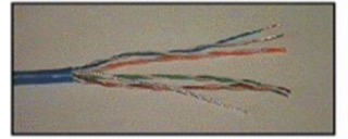
Unshielded Twisted Pair (UTP)
Shielded Twisted Pair (STP)
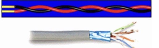
Twisted Pair Cable
Twisted wires cancel magnetic fields, reducing interference.
Twisting reduces unwanted induced signals.
UTP (Unshielded Twisted Pair) – no ground shield.
STP (Shielded Twisted Pair) – ground shield reduces external signal interference.
High Tension Cables
Operating voltage over 600 V.
Mainly used in engine ignition systems (up to 40,000 V).
Single-core stranded, insulated, and metal braided screened to prevent interference.
Also used in: strobe systems, unregulated frequency wild generators, and hybrid/electric aircraft battery packs.
Spec 55: 600 V (single wall), 1000 V (dual wall).
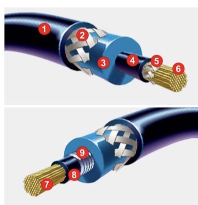
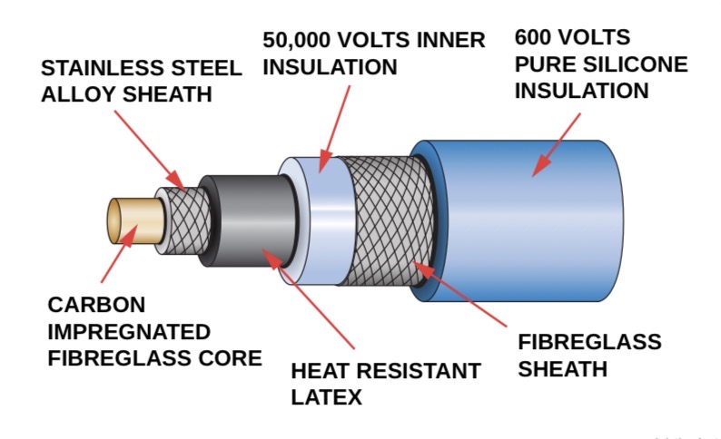
Piston Engine Ignition Cable Construction
Silicone jacket – heat, cold, chemicals, moisture.
Reinforcing member – strength & terminal retention.
Silicone insulation – dielectric & heat performance.
Conductive silicone layer – EMI/RFI suppression.
Fibreglass braid – strength.
Carbon impregnated fibreglass core – conductivity.
Kevlar® reinforcement – strength.
Ferrite layer – EMI/RFI suppression.
Wire-wound layer – EMI/RFI suppression.
High Tension Cable - Picture
Spec 55 Insulated System - Single Wall
Spec 55 Insulated System - Dual Wall
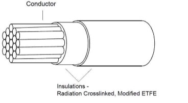
Ignition Cable (Piston Engine)
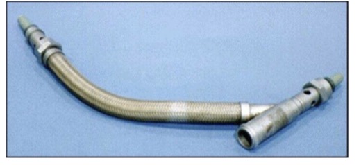
High-Tension Ignition Cable Terminations
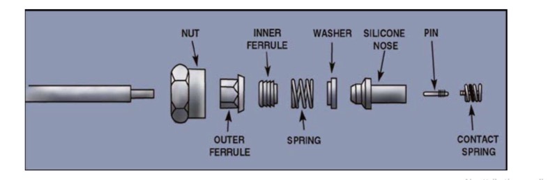
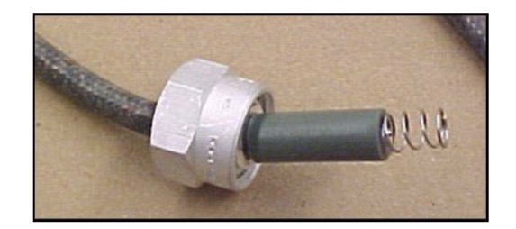
Connected using special end fittings with springs or contact caps, secured to the conductor, insulation, and threaded coupling assembly.
High-Tension Ignition Cable End Exploded View
High-tension ignition Cable Termination Picture
High Tension Cable for Piston Engine
Warning - Igniter Plug
Igniter plug discharge can be up to 2,000 amps.
Low battery voltage does not reduce discharge power, only the rate of spark discharge.
HEIU output voltage can cause significant injury.
Isolate input power and wait at least 1 minute before working on the system.
Short the capacitor before working inside the HEIU.
Coil and magneto systems have higher voltage but lower current than HEIUs.
1: High temperature "Class E" silicone jacket to withstand heat, cold, chemicals and moisture.

2: Reinforcing member for added strength and terminal retention.

3. Silicone insulation for superior dielectric and heat performance.

4. Conductive silicon layer for high temperature performance and EMI/RFI noise suppression.

5. Fiberglass braid for maximum strength

6. Carbon impregnated berglass core for superior support conductivity.

7. Core reinforced with KEVLAR®.

8. Layer impregnated with Ferrite.

9. Wire-wound layer to suppress EMI/RFI noise.

Spark Plug Wires
Carry over 20,000 volts from the distributor cap to the spark plug.
Fibre core carries the high voltage.
Older metallic core wires caused electrical interference.
Some have a locking connection at the distributor cap.
To remove: remove the distributor cap first, squeeze the terminals together, then remove the spark plug wire.
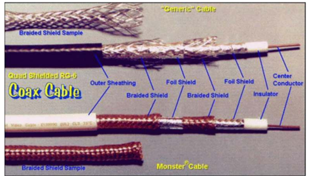
Coaxial Cabel
Used to connect electronic equipment to antennas.
Prevents radio frequency interference (RFI).
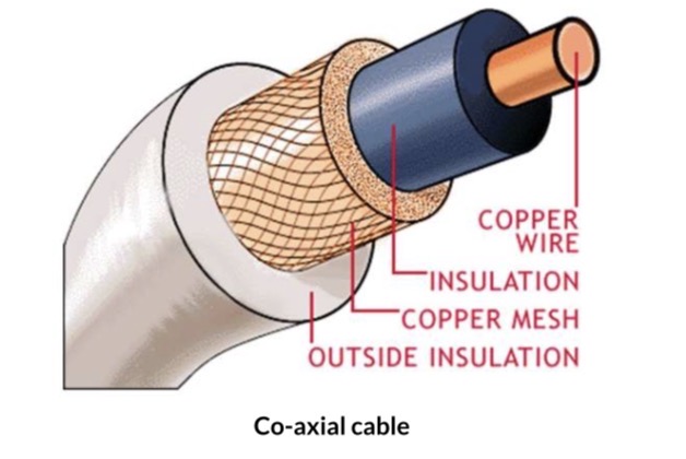
Two conductors:
Centre conductor covered by a dielectric.
Outer conductor covered by a protective sheath.
Do not kink, squash, stand on, or drop tools on the cable – it will become unserviceable.
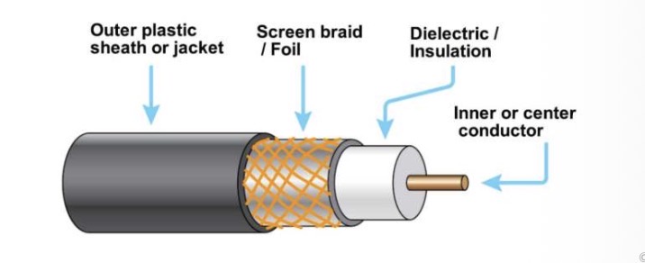
Coaxial Cable Construction
Centre conductor: solid or stranded copper (plain, tinned, silver plated, or gold plated).
Dielectric: polyethylene or Teflon®.
Outer conductor: fine wire braid.
Outer jacket: protects against weather, fluids, mechanical and electrical damage.
Used in: communication, navigation, and capacitance fuel quantity indicating systems.
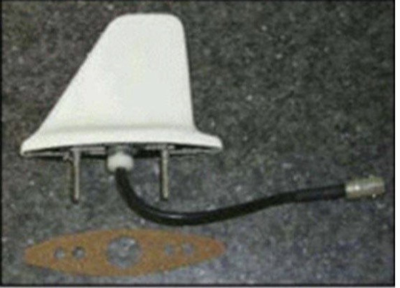
Antenna connected using co-axial connector
Coaxial Cable Construction
Coaxial Cable Advantages
Shielded against electrostatic and magnetic fields.
Does not radiate or pick up external interference.
Common impedance: 75 Ω.
Damage that changes the cable’s coaxiality changes its impedance, degrading or stopping equipment operation.
After insulation testing, always short the cable before reconnecting to prevent equipment damage.
Co-axial Cable Diagram
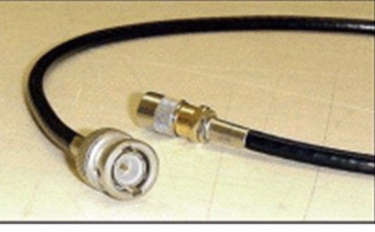
Typical Co-axial Lead with BNC Connector
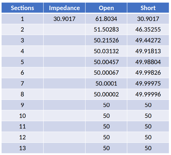
Impendence Calculations of Coaxial Cable
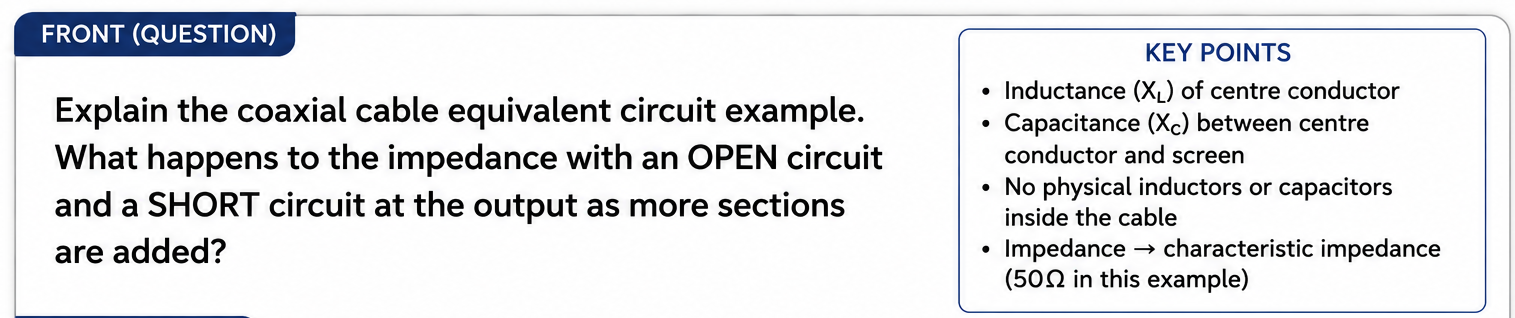
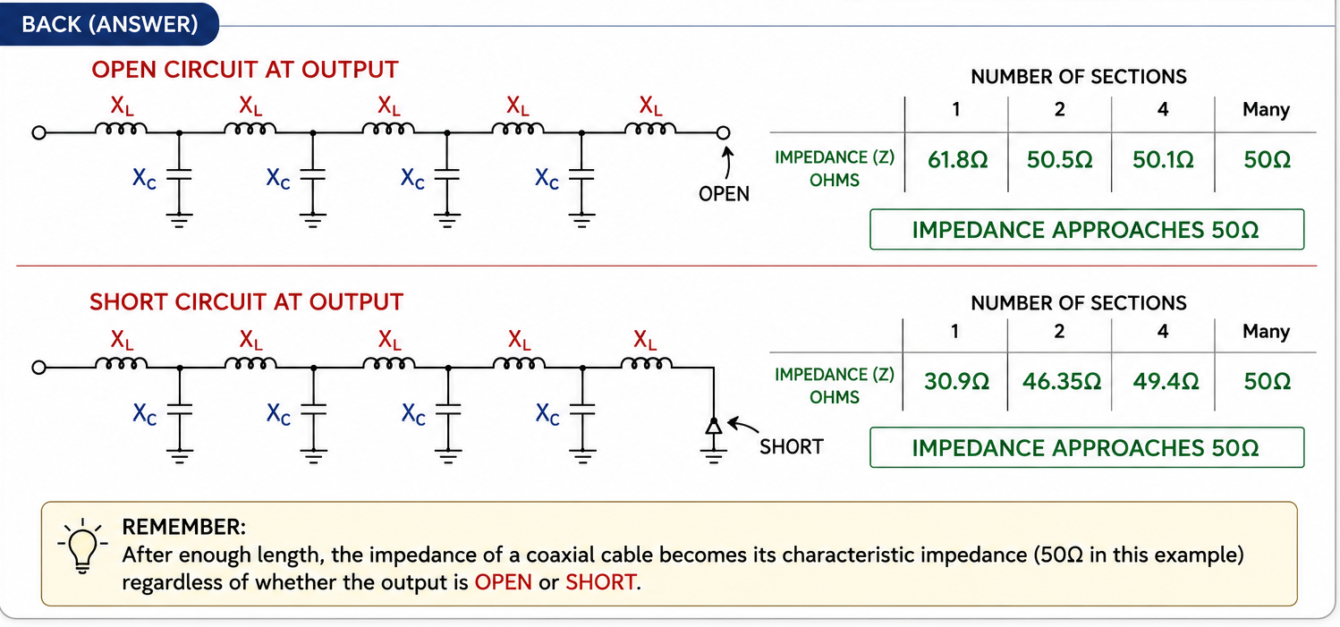
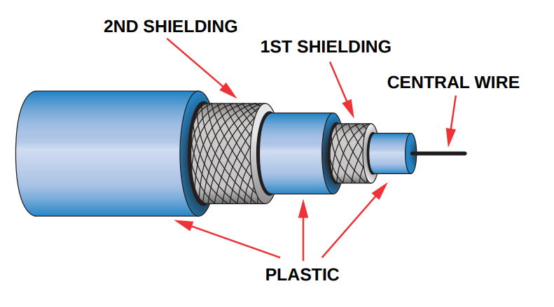
Triaxial Cable
Three Parts (Remember: Signal → Return → Noise)
Centre wire → Carries the signal.
First shield → Return path for the signal.
Second shield → Carries external noise to ground.
Used For
Antenna cable for very sensitive signal detection systems.
Example: Automatic Direction Finder (ADF).
Multiple Layers of Shielding
Triax Cable
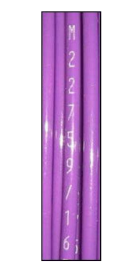
MIL-W-22759 Aircraft Wire
is commonly used in new aircraft wiring installations.
Always consult the manufacturer's Service Manual (AMM) and Service Bulletins (SBs) before replacing aircraft wiring.
Check for the correct:
Wire type
Wire size
All aircraft wire must have its type identification imprinted along its length.
Memory Trick
"22759 = Check Manual, Check Size, Check Stamp."
MIL22759
Crimping
Attaches a terminal/contact to a conductor without solder.
Uses compression (deformation) of the terminal barrel around the conductor.
Creates a homogenous mass between the conductor and terminal.
Produces a strong mechanical and electrical connection
A Good Crimp should ?
Be as strong as the conductor.
Have good electrical conductivity.
Not introduce impedance or signal discontinuity.
Use the correct combination of:
Conductor
Crimp barrel/terminal
Crimp tool
Advantages of Crimping
Faster and easier fabrication.
Uniform operation.
Good electrical conductivity.
Lower voltage drop.
Strong connections (as strong as the conductor).
Eliminates solder-related problems (solder slop and flux).
No dry solder joints
Crip Types
Ring terminal
Slotted terminal
Hook-type terminal
Ring terminal (lug) is the most commonly used.
Preferred because it virtually eliminates circuit failure due to terminal disconnection.
Memory Tip
Ring = Reliable (most secure, least likely to disconnect).
Splices
A method of connecting conductors using a crimped connector.
Usually a permanent connection using a self-insulated splice connector.
Permitted only if it does not affect the reliability or electromechanical characteristics of the wiring.
Maximum of one splice is allowed in any one wire segment between two connectors or disconnect points.
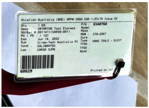
Crimper calibration must be checked before use by verifying the calibration label/sticker is current.
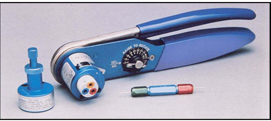
Refer to MIL-C-22520 for crimping tool requirements.
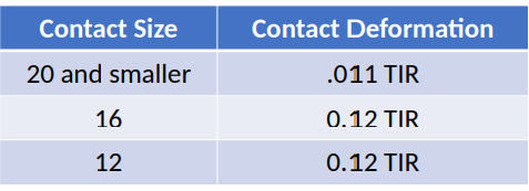
TIR (Total Indicator Reading) measures the total deviation from the true centre line after a contact is crimped.
Crimping Tool Calibration Label
Contact Size and Deformation by crimper
MIL-C-22520 Crimping Tool
Types of Electrical Connectors
M (Motion Picture) Series (1925):
Mechanical locking ring to prevent accidental disconnection.
P (Paramount Studios) Series:
Introduced die-cast shells, moulded pin inserts and latch locking devices.
F (Fox Studios) Series:
Introduced the threaded coupling ring.
Adapted for the Douglas DC-1 and later aircraft.
Led to the AF firewall connector, the first hostile environment connector for aircraft.
Most common aircraft connectors are AN (Army-Navy) and MS (Military Specification).
AN connectors have been superseded by MS connectors (same part number, AN replaced with MS).
Installed on wiring that is frequently disconnected.
Power supply side is typically connected to the socket to reduce the chance of an accidental short when connectors are separated.
Commonly used on avionic components with multi-pin connectors for easy maintenance.
Military Connector Specifications
Standardise aircraft and military connectors.
Ensure reliability, performance and environmental protection.
Define:
Housing dimensions
Insert layout
Operating characteristics
Approved manufacturers are listed on the Qualified Products List (QPL).
Crimped contacts are generally used.
Use environmental-resistant connectors where there are fluids, vibration, shock or corrosion.
QPL
Qualified Products List
Millarary Specs
ensure reliability, performance and environmental protection.
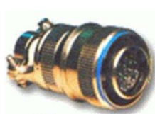
Plug
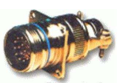
Receptacle
Connector Housings
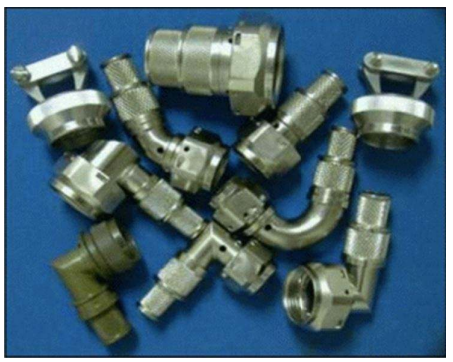
Connector Identification
Designed to meet military specifications.
Adapted for use in most aircraft.
Reference identification must remain legible throughout the life of the aircraft.
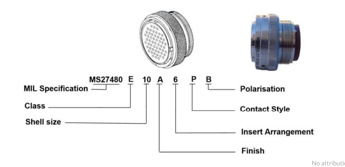
Military Specication Connector Identication
Military specifications (MIL specs) vary greatly.
Part number descriptions can vary between MIL specs.
Refer to the applicable MIL spec and part number to determine a connector's exact characteristics.
MIL Spec Part Number Breakdown