Signal Processing (pt. 1)
 Call Kai
 Learn
Learn Practice Test
 Spaced Repetition
 Match
Match Flashcards
 Knowt Play
1/28

There's no tags or description
Looks like no tags are added yet.
Name | Mastery | Learn | Test | Matching | Spaced | Call with Kai | Chat |
|---|
No analytics yet
Send a link to your students to track their progress
29 Terms
Timer
Coordinates the sending, receiving and display of signals
Keeps track of when sound is sent and how long it takes for echoes to return
Range Equation
Distance to reflector = (propagation speed x pulse round trip travel time) ÷ 2
13 µsec
= 1 cm on screen
Beamformer
Essential for electronic transducers
Pulse-Delay sequences produce dynamic focusing, electronic steering, dynamic focusing, and apodization
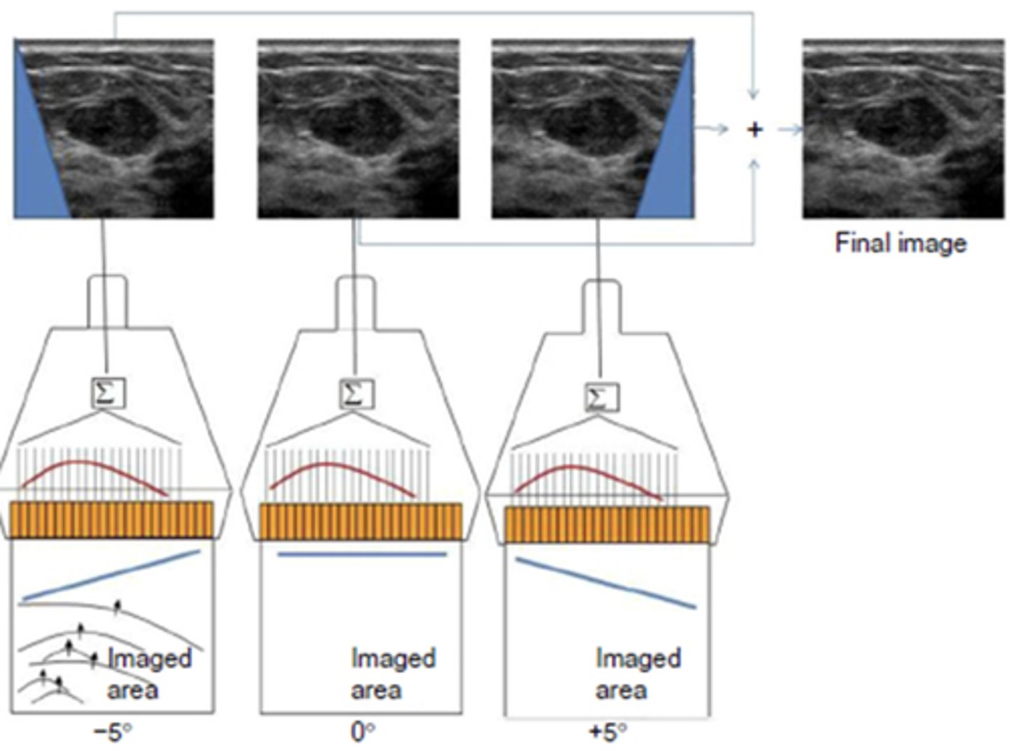
Electronic Steering
Phased array scan lines
Doppler cursor positioning
Color box adjustments
Apodization
Greatest energy in center of array - sending and receiving signals
Decreased energy on outer edges of array
Produces grating/side lobes
Transmitter/High Voltage Pulse Generator (HVPG)
Generates short electrical pulse that starts vibration of crystal
Determines energy of sound wave
Controlled by adjusting acoustic output/power/intensity
Must be electronically matched to transducer
Exams that use lower voltages/power (MI & TI)
OB
GYN
Exams that use mid to higher voltages/power (MI & TI)
Cardiac
Cirrhotic Liver/Fatty Liver
Obese patients (penetration)
Transducer
Where electrical energy is converted to mechanical energy, then back into electrical energy
Piezoelectric properties - Resonance frequency of crystal, transmits and reflects radiofrequency signals, damping
Resonance Frequency
Natural frequency of crystal
Damping
Removes energy from crystal
Makes pulses shorter - broad bandwidth
Used in PW Doppler
Transmit-Receive Switch
Located between transducer and detector - surge protector that protects electrical components
Only accepts signals < 1 Volt
First component signal moves through after transducer
Frequency Passband Filter
Designed for broadband/multi-frequency transducers and harmonic imaging
Deterioration may harm receiver electronics
May be integrated as part of transmit-receive switch or function separately
Detector
Receives variety of information from returning signals:
Amplitude - basis for brightness
Time of arrival - basis for location
Frequency - basis for Doppler & harmonic imaging
Phase - basis for Doppler direction
Tissue speed - basis for shear wave elastography
Receiver
Processes the electrical voltage signal detected by the crystal
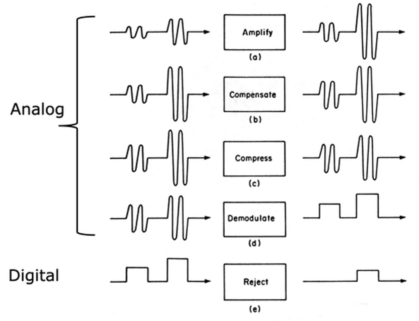
Sequence of Receiver Functions
Amplification
Compensation
Compression
Demodulation/Rectification
Rejection
Pre-Amplification
Happens before true amplification
When small amplifier is placed in transducer assembly
Occurs before signal reaches the cable within transducer
-> Generates low-level noise that affects signal to noise ratio
Not adjustable
Amplification
Uniformly amplifies all returning signals
Converts small received signals to larger ones suitable for processing
-> Determines overall gain
Gain
Ratio of output to input electric power
Compensation
Allows for uniform display of similar tissues despite differences in depth
Compensates for attenuation & more for higher frequency transducers
-> controls TGC, DGC, Near/Far Gain
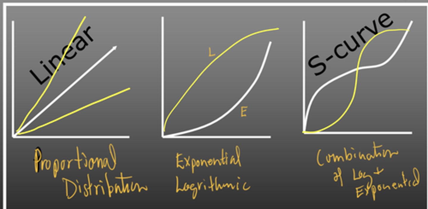
Compression
Proportional decrease in signal amplitude
-> controls dynamic range (how many shades of grey)
Linear, logarithmic, and exponential methods
Rectification
Converts alteration current to direct current - negative to positive
Half-Wave Rectification
Diode only conducts signal during positive portion of cycle
Full-Wave Rectification
Diode converts all signals into output
Demodulation
Converts voltages in receiver from one form to another
Smoothing
Rejection
Eliminates smaller amplitude signals produced by weak echoes
-> wall filter or reject
Signal to Noise Ratio (SNR)
Strength of echo signal compared to random noise level
Want higher echo signal than noise
Techniques to Improve SNR
Change location of amplifier within system
Internal & external shielding of system
Limited cable length
Cable sheilding
Noise free power source