3D CMM
 Call Kai
 Learn
Learn Practice Test
 Spaced Repetition
 Match
Match Flashcards
 Knowt Play
1/26

There's no tags or description
Looks like no tags are added yet.
Name | Mastery | Learn | Test | Matching | Spaced | Call with Kai | Chat |
|---|
No analytics yet
Send a link to your students to track their progress
27 Terms
Trends in parts to be measured:
rotationally symmetric parts with freeform shapes
prismatic parts with small bores
flat metal sheet parts with limited shape stability
2D parts with bores and cutouts
Probe types:
touch-trigger probes
optical (non-contact) probes
Conventional 3D CMM:
measured 3D complex shapes
trends: smaller dimensions, tighter tolerances
reduced mesauring uncertainty
four main error sources: geometric, thermal, abbe error and finite stiffness
Specifications in design of the new 3D CMM:
low measuring volume
lowe measuring uncertainty
incremental position-measurement system
platform for different probe types
Approches for 3D CMM elimination of errors:
minimize finites stiffness and thermal errors by mechanical design
reduciton of geometric errors by machine concept
software compensation of ersidual geometric errors
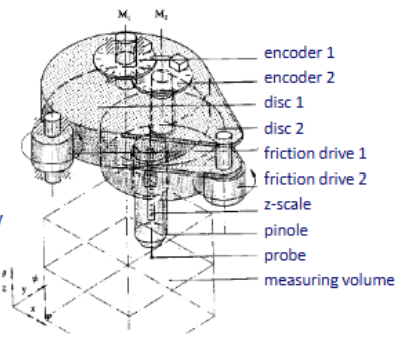
Describe concept 1
= polar coordinate based measuring coecpet using two rotating discs with friction drives and encoders
tight requierements on parallelism of the rotation axes
bearing are in one plane to avoid tilting
preloaded hollow rollers acting as a nest of spring
→ rejected because how accurately would the rotations be
Describe concept 2
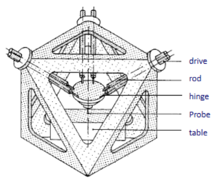
= 6 actuated rods connecting to a fixed base to a moving platform that carries the probe/table
elastic hinges introduce elasticity, avoid hysteresis
pros: flexible movement (full 6 DOF control), limited number of errors
cons: large size, tight temperature stability requierements
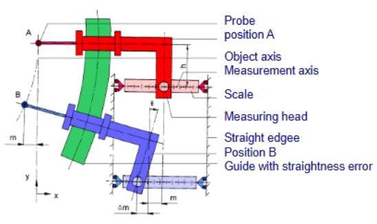
Describe the Abbe principe
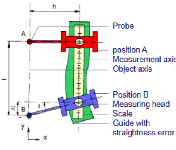
= straightness error causes a measurement error that is linearly proportional to the offset h between the probe and the scale
→ always place the measuring scale in line with the actual point of measurements
Describe concept 3
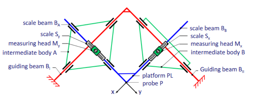
= machine concept with intermediate bodies
while moving in the x and y direction, the measuring systems stay pointed to the probe
guiding beam B_I does not cause measuring error due to the application of the Abbe principle
scale beam B_A does not cause measuring error due to the application of the Bryan principle
Describe the Bryan principle
= a straightness error that is measured at the offset h that causes a measurement error that is linearly proportional to the offset between the scale and the probe
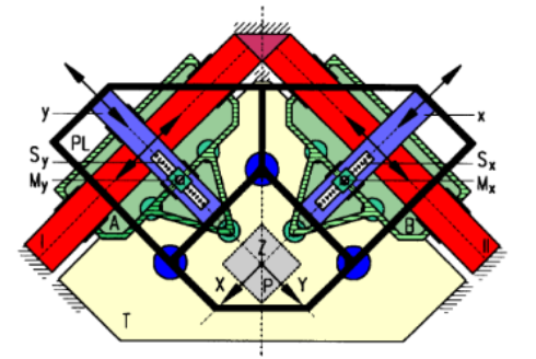
What is the final kinematic design of the 3D CMM?
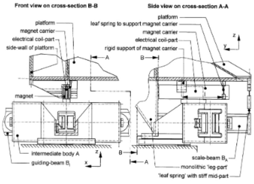
= a 3 body system (platform, intermediate body A (constrains x and Rz), intermediate body B (constrains y))
measuring systems stay pointed at the probe
bearing far apart for improving stability
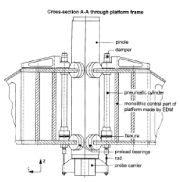
vertical guide (pinole) is integrated into the platform, driven almost in the COG
Describe what are the geometric errors for a single moving body and how do they apply for the 3D CMM?
For a single moving body:
the error vector contains T=translational error, R=rotational error and P=position erro
straightness error == TOTAL ERROR VECTOR
For the 3D CMM:
there are 30 possible errors= 18 rotational, 3 straightness and 9 translational errors.
By applying the Abbe and Bryan principles, those error reduce from 30 to 13 = 2 rotational, 8 translational (2 intermediate body A, 2 intermediate body B, 1 flatness of the table, 1 of the z direction, 2 of the vertical beam) and 3 straightness errors
What are the two concepts tackled for the machine frame of the 3D CMM? Explain in detail.
Geometry and material/
For the geometry, a closed box plate constructions were used in the pyramid shape for optimal material utilization, force transmission through plate plane was accounted for (light and stiff moving parts), monolothic parts were used (prevents hysteresis, improves stiffness and thermal conductivity), parts are glued togethers.
For the material, aluminium was used for its excellent thermal behaviour. It is very respondent to heat; however, it reaches a thermal equilibrium very fast. To add, it has low density, therefore, light moving parts with thicker plates.
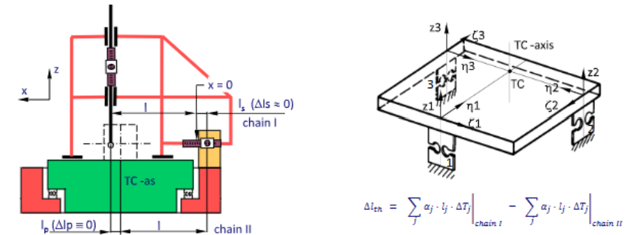
Explain how the passive compensation of thermal expansion works.
By using thermal centers, Zerodur scales (a glass-cermaic with near zero thermal expansion used for the actual position scales) and temperature measurement of the product
= method used to cancel out uniform themral explansion using symmetric thermal chains
additionally, room temperature requirement needs to be satisfied due to uncertainties in thermal expansion and non-uniform temperature distribution
Explain why are direct drives a good choice to move the slides.
There is no gearbox, no mechanical transmission, no belts.
It is a simple design and maintenance free, high dynamic characteristic, small position errors, no friction, no backlash, small power dissipation, no cogging or transversal attracion, additional damping via controller software, weight compensation of vertical slide
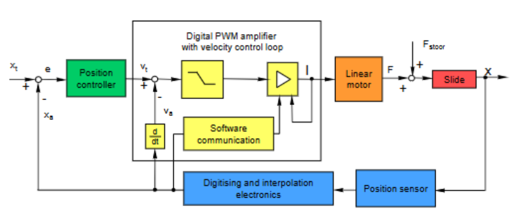
Describe the positioning control loop.

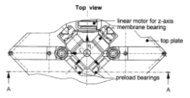
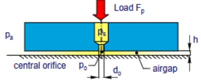
Describe the air bearing in the 3D CMM.
+frictionless, high guiding accurcay, clean operation, long stroke motion capability
-need preload and self-alignment
Kinematic design principle: minimum constraint design =
= use the exact number of constraint points needed
overconstraint causes stress
undersonstraints causes play
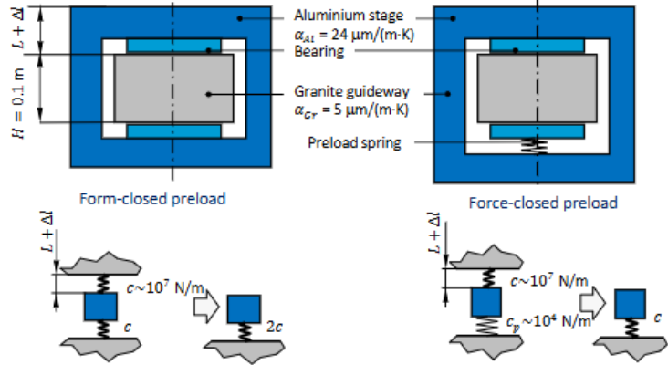
Describe the difference.
Form-closed bearings: mismatch thermal expansion, rigidly constrained, generating internal stress since both sides are stiff
Force-closed bearings: more tolerant of dissimilar thermal expansion and lower overall stiffness
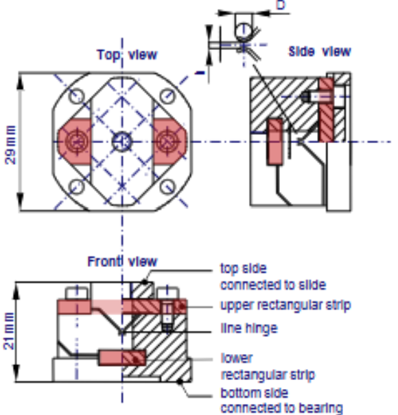
Describe what is the elastic cardan.
= flexture based mounting that allows the air bearing to self-align with the guiding surface without any hysteresis
two orthogonal hinges, located in the same horizontal plane
no hysteresis
compact
horizontal strips prevent sideways deflections
How is vibration isolation done?
During preparation and during measurement. Explain in detail why it happens.
Through a machine table carried by pneumatic springs to isolate from ground vibrations.
During measurement preparations, the load changes and causes a tilt, resulting in a deformation component under gravitational force and extra driving force, therefore, a quasi statis machine levelling system was implemented, which becomes stable after 20s.
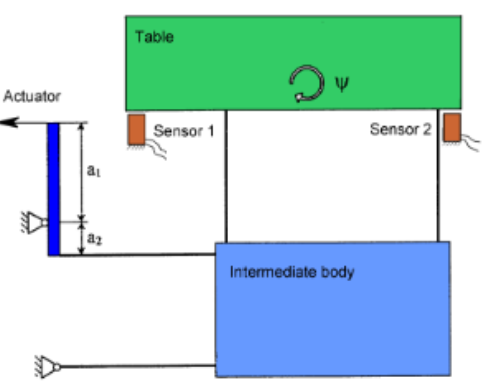
During measurement, an active electromagnetic system prevents tilting due to mass travelin and changng load distribution, tilting the machine. It is done by differential tilt measurement (sensor 1-2) and feedback by controller and amplifier to the voice coil actuator.
Resulting in low power dissipation, vibrations are isolated, force is enlarged bua a cantilever (1/10).
How does horizontal vibration isolation works?
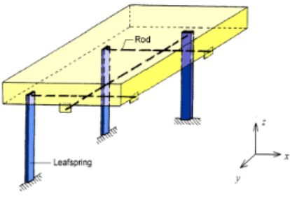
By using flexures (rods) for no play and no hysteresis. They are NOT at COG.
horizontal motion → rotation → vertical motion → damped by vertical dampers
What is calculated in the error budget of the 3D CMM?
finite stiffness - right design principles to geomtery and assempy
thermo mechanical errors - extensive use of aluminium, mechanical thermal lenght-compensation
geometric errors - through straightness errors, Abbe and Bryan principles, machine concept, calibration
How is calibaration done by NMi VSL standards?
Via a interferometer (calibrating geometric errors)
Via a polyglo mirror (to determine perpendicular beams)
Via sensitivity and diameter of a reference ball (probe calibration)