Pulse Code Modulation (PCM) and Digital Transmission
 Call Kai
 Learn
Learn Practice Test
 Spaced Repetition
 Match
Match Flashcards
 Knowt Play
1/24

Earn XP
Description and Tags
Vocabulary flashcards covering core concepts of Pulse Code Modulation (PCM), sampling, quantization, encoding, dynamic range, noise types, and system architecture based on lecture notes.
Name | Mastery | Learn | Test | Matching | Spaced | Call with Kai | Chat |
|---|
No analytics yet
Send a link to your students to track their progress
25 Terms
Sampling
The process of converting a continuous-time signal into discrete-time signals by taking a sufficient number of samples so that the original signal can be completely represented and reconstructed.
Sampling Theorem
A theorem stating that a continuous-time signal may be completely represented by its samples and recovered back if the sampling frequency fs≥2fm, where fs is the sampling frequency and fm is the highest frequency present in the signal.
Nyquist Sampling Theorem
A theorem establishing that the minimum sampling rate (fs) must equal twice the highest input frequency, expressed mathematically as fs=2fm.
Aliasing
An impairment, also known as foldover distortion, that occurs when the sampling frequency fs<2fm, causing alias side frequencies from the first harmonic to fold over into the audio spectrum where they cannot be removed through filtering.
Anti-Aliasing Filter
A bandpass or low-pass filter with bandwidth B required before sampling to prevent aliasing of the message signal.
Quantization
The process of converting an infinite number of amplitude possibilities in an analog signal into a finite number of conditions or discrete levels.
Encoding
The process in which an encoder designates each quantized level with a binary code, thereby minimizing the bandwidth used.
Quantization Error (Qe)
The round-off error produced during A/D conversion, calculated as the difference between the original sample voltage and the quantized level (Qe=sample voltage−quantized level).
Quantization Noise (Qn)
An alternative term for quantization error, so named because altering the signal amplitude acts as additive white noise.
Quantization Step Size (Δ)
The uniform step size for M=2n quantization levels operating across a voltage range from −V to +V, given mathematically by Δ=2n2V=V(2−n+1).
PCM Bandwidth (BPCM)
The channel bandwidth required for PCM transmission, evaluated as BPCM≥nB using sinc functions as an orthogonal basis, or BPCM≥2nB using rectangular pulses, where B is signal bandwidth and n is bits per sample.
Dynamic Range (DR)
The unitless ratio of the largest possible magnitude (Vmax) to the smallest possible magnitude or quantum value (Vmin) that can be decoded by receiver DACs with acceptable distortion (DR=VminVmax).
Dynamic Range in Decibels (DRdB)
The dynamic range expressed in decibels, given by DRdB=20log(VminVmax)≈6ndB, where n is the number of magnitude bits in the PCM code.
PCM Bit-Dynamic Range Relation
The mathematical formula relating dynamic range DR and the number of PCM magnitude bits n (excluding sign bit), expressed as 2n−1≥DR or minimum bits 2n=DR+1.
Coding Efficiency
A numerical indication of how efficiently a PCM code is utilized, calculated as coding efficiency=actual number of bits (including sign bit)minimum number of bits (including sign bit)×100.
Signal-to-Quantization Noise Ratio (SQRdB)
The ratio of average signal power to average quantization noise power in dB, given by SQR(dB)=10log((q2/12)/Rv2/R)=10.8+20log(qv), where v is rms signal voltage and q is quantization interval.
Overload Noise
A type of quantization noise that occurs during A/D conversion when the input signal amplitude is too large for the quantizer range.
Random Noise
A type of quantization noise that occurs during A/D conversion when the input signal amplitude is too small.
Granular Noise
A type of quantization noise produced during A/D conversion characterized by non-uniform error jumps.
Hunting Noise
A type of quantization noise that occurs when there is too long of a quiet time in the input signal.
Nonuniform Quantizers
Special quantizers, such as μ-law and A-law quantizers, used to reduce quantization error and increase dynamic range when the input signal is not uniformly distributed.
DS-0 Signal
A standard digital PCM voice signal bandlimited at 4kHz sampled at fs=8000samples/second with n=8bits/sample, resulting in a bit rate R=64kbits/second.
Regenerative Repeater
Devices placed along a telephone line transmission path that clean up and regenerate PCM signals to prevent noise accumulation.
PCM System Block Diagram
The full end-to-end architecture of a Pulse Code Modulation transmission system, showing the transmitter, channel with repeaters, and receiver components.
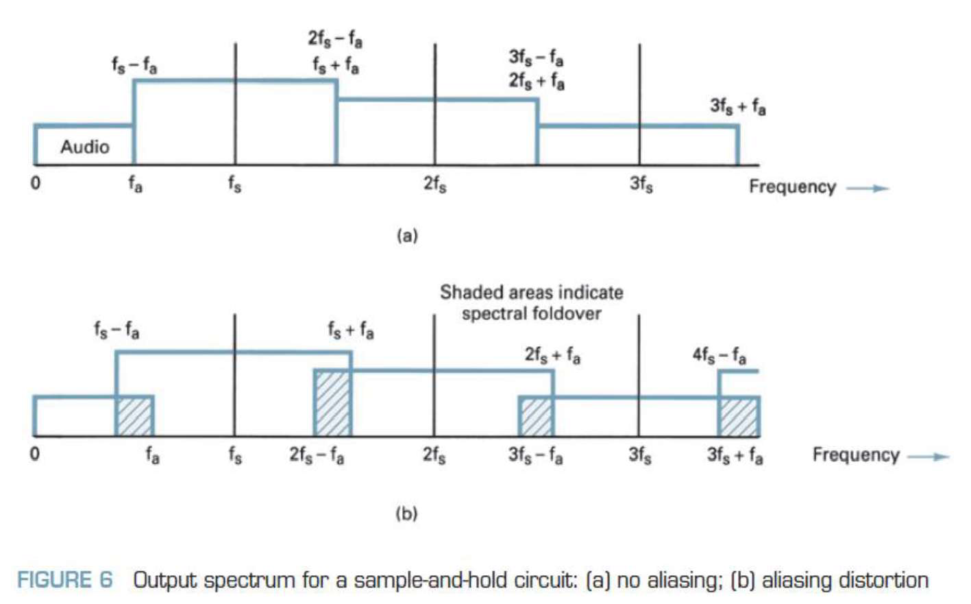
Sample-and-Hold Output Spectrum Diagram
A frequency spectrum diagram showing (a) normal output with no aliasing when fs≥2fa and (b) spectral foldover aliasing distortion when fs<2fa.