Module 8 - High Voltage Production & Control
1/38
There's no tags or description
Looks like no tags are added yet.
Name | Mastery | Learn | Test | Matching | Spaced |
|---|
No study sessions yet.
39 Terms
X-ray production requires a
step-up high turns
ratio transformer
A HV transformer can increase 50-240 volts up
to
30-150 KV
Why is the voltage transformer immersed in high dielectric oil
To prevent arcing
The center tap for a HV Transformer creates
less potential reference to
ground for the HV cable
The diodes are located
in a tank of dielectric
oil along with the HV transformer
The diodes are also called
Sticks
What can be used to test the diodes
A megger
Diode sticks should always be replaced in
Pairs
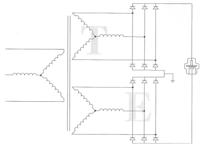
Phase and Pulse
3 Phase
6 Pulse
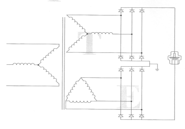
Phase and Pulse
3 Phase
12 Pulse
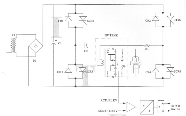
High frequency inverter
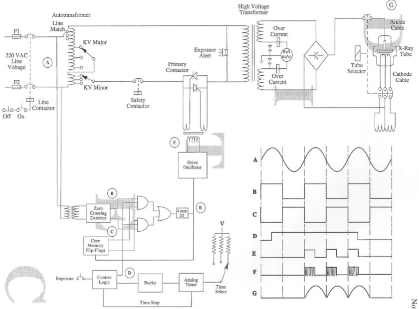
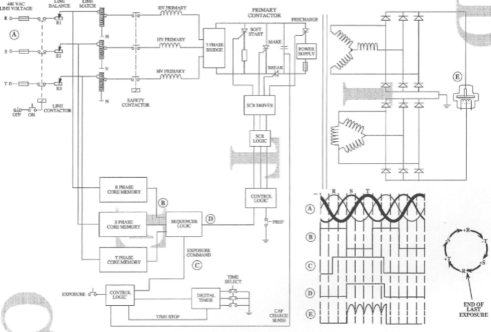
Line Match
Selectable taps allow the installer to program
the input circuitry to produce the required
operating voltages based on the measured
value of the incoming line voltage
KV Selection Device
The component that delivers voltage to the primary of the
HV transformer
Pre reading KV meter
measures the
selected output of the KV control device and
displays the KV value that should be
produced when that voltage is delivered to
the high voltage transformer
Load Compensation
Compensates for the I2R load loss that occur
in the HV transformer
Usually done by increasing the primary
voltage to the HV transformer when mA is
increased
Primary Contacting
Method of controlling exposure time
Primary contactors are usually SCRs
Single Phase, Self Commutation
SCR is the primary contactor
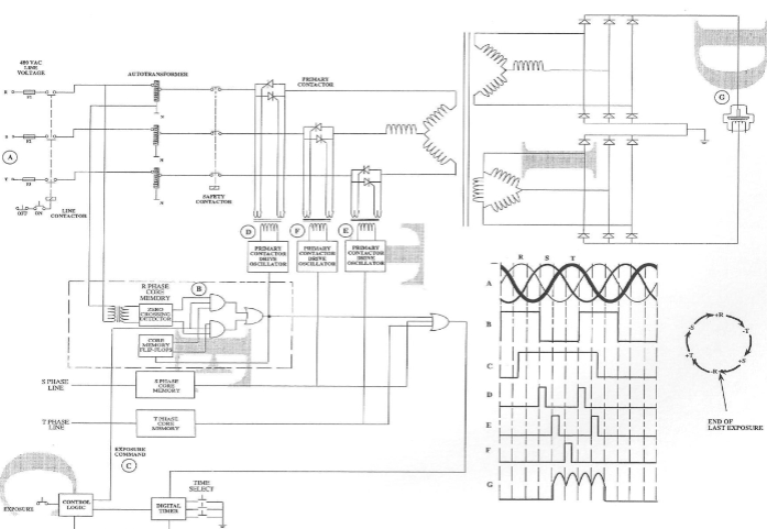
Three phase self commutation
Self Commutation
removes the gate pulse and waits for the incoming voltage
to hit the zero crossover point. The SCR current will drop below the holding current and shut off
This method requires two SCRs for each phase of
incoming voltage
3 phased 12 pulsed
forced commutation
Forced Commutation
This method removes the SCR gate pulse and
applies a reverse voltage across the SCR.
The reverse bias is usually supplied by a bank
of capacitors that were charged prior to
exposure
Requires only two SCRs
Pre charge circuit
Used to charge the commutation capacitors prior
to exposure
Soft Start SCR (pre-contacting
SCR)
An SCR in series with a resistor is placed in
parallel with the contacting SCR and fired a
few milliseconds before the make SCR
Reduces KV overshoot
Maximum Filament Current
Limiter
limits the absolute value of filament
current, 5.0 to 6.5 amps
Standby Adjust
Sets the continuous filament current, while the
machine is in standby mode, 2.0-3.0 amps
Baseline Adjust
Sets the starting filament current values that will
produce the desired mA
Spacecharge Compensation
Makes electrons ready to shoot x rays
ma Sensing
monitors the current flowing form the
cathode to the anode
mA Stabilizer
Compares the actual mA to selected mA and
increases or decreases the filament mA to correct
for any differences

Tube Protector
Tube Protector 2 functions
Prevents exceeding maximum
Limit maximum generator output
Types of radiation sensors
Photo multiplier
Ionization Chamber
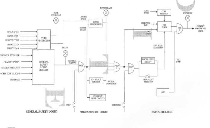
Control Logic
Control Logic
3 major areas
General safety
pre exposure
exposure
General Safety
This area of control logic monitors the
condition of the x-ray system at turn on
Pre Exposure 1
boosting of filaments, starting anode
rotation, driving KV motor and charging commutation
capacitors
Pre exposure 2
feedback from the circuits in Pre-exposure
1 are added and sent to exposure area
Exposure
Bucky mechanism is started
Primary drive pulses are generated at
appropriate zero crossover of incoming line
voltage (core memory)