Radio Wave Propagation
 Call Kai
 Learn
Learn Practice Test
 Spaced Repetition
 Match
Match Flashcards
 Knowt Play
1/75

There's no tags or description
Looks like no tags are added yet.
Name | Mastery | Learn | Test | Matching | Spaced | Call with Kai | Chat |
|---|
No analytics yet
Send a link to your students to track their progress
76 Terms
RADIOWAVE PROPAGATION
Refers to the behavior of radio waves as they travel from one point to another.
WAVE PROPAGATION
It is the transfer of electromagnetic waves from one point to another.
radio waves
EM waves are also called
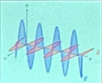
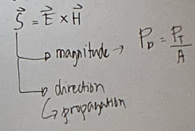
Poynting vector
Represents: Average power density and instantaneous power flow
TRANSVERSE WAVES
Propagation is PERPENDICULAR to its direction.
Includes radio waves travelling through free space
LONGITUDINAL WAVES
Propagation is PARALLEL to its direction.
Elements of a wave
λ - length of 1 cycle
T - time for 1 cycle
f - cycles per 1 second
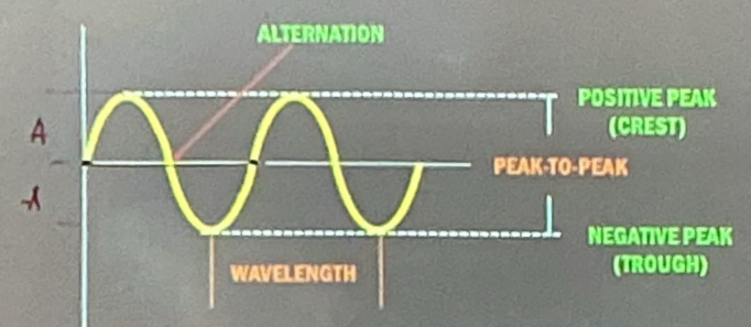
Wavelength
Distance that a wave travels in the time of one cycle
λ = c/f
Wave velocity
Speed of the wave depending on the type and nature of the propagation medium
refractive index of air
n = 1.0003
n = 1.33
refractive index of water
n = 1.55
refractive index of glass
Relationship of refractive index, density and velocity
↑n = ↑ρ = ↓v
Frequency range of ELFs
30-300Hz
EVVLMHVUSEI acronym meaning
Every, Very, Very, Loving, Mother, Has a, Very, Ugly, Son, Except, I
Frequency range of VFs
300-3000Hz
Frequency range of VLFs
3-30kHz
Frequency range of LFs
30kHz-300kHz
Frequency range of MFs
300kHz-3MHz
Frequency range of HFs
3MHz-30MHz
Frequency range of VHFs
30MHz-300MHz
Frequency range of UHFs
300MHz-3GHz
Frequency range of SHFs
3GHz-30GHz
Frequency range of EHFs
30GHz-300GHz
Medium Frequencies
AM is included in the frequency range
Very High Frequencies
FM is included in the frequency range
1GHz - 100GHz
Microwave frequency range
Ultra High, Super High, Extremely High
Microwave is included in the frequency range
ISOTROPIC ANTENNA
CAN RADIATE UNIFORMLY IN ALL DIRECTION
Ideal antenna
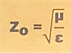
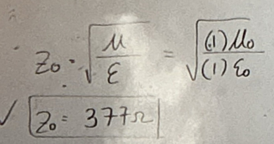
WAVE IMPEDANCE
Also called the characteristic impedance for which the medium is alr.
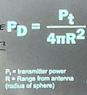
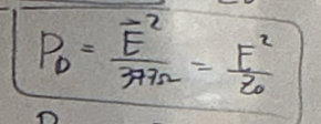
POWER DENSITY
It is defined as the ratio of the transmitter power over the area at which it is distributed (P/A)
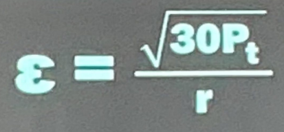
FIELD INTENSITY FIELD STRENGTH
The quality of the electric field at any given point in volt per meter or a potential of 1 volt induced in an antenna wire 1 meter long.
Wave impedance in air
Power density in terms of Energy
POLARIZATION
Refers to the property of certain electromagnetic radiations in which the direction and magnitude of the vibrating electric field are related in a specified way.
LINEAR
The orientation of a linearly polarized electromagnetic wave is defined by the direction of the electric field vector.
CIRCULAR
Electric vector rotates about the axis of the direction of propagation
ELLIPTICAL
Electric vector rotates about the axis of the direction of propagation but the amplitudes of its two linearly polarized components are unequal.
RANDOM
There is no fixed pattern of polarization variation
ATTENUATION
Electromagnetic waves are attenuated as they travel outward from their source.
Proportional to the square of the distance travelled
REFLECTION
The bouncing of waves as it strikes a conductive surface
DIFFRACTION
An EM Wave that meets an obstacle tends to bend around it or a slit with a size comparable to their wavelength
SCATTERING
Diffusion of a wireless signal when it encounters an uneven surface of the object
ABSORPTION
Source of energy of the electromagnetic waves are transferred to the atoms and molecules of space.
INTERFERENCE
Occurs when two waves combine in such a way that the system performance was degraded (collision of waves)
SURFACE/GROUND WAVE
Travels around the curvature of the earth, sometimes right around the globe.
Utilizes frequencies below HF range, and losses with increasing frequency.
The higher the frequency, the shorter the wavelength, means more prone to absorption.
AM
becomes highly impractical at higher frequencies (such as HF and above) primarily due to severe tilting of the wave front caused by earth induced losses and rapid ground attenuation
Vertical - to reduce attenuation
Polarization of surface wave
SPACE WAVE / LOS
Travels in the troposphere; the portion of the atmosphere closest to the ground.
Depends mostly on line-of-sight conditions; limited in propagation by the curvature of the earth.
Caused by the varying density of the atmosphere due to diffraction around the curvature of the earth.
FM, microwave
SKY WAVE
The wave strikes the Ionosphere and is refracted back to the ground.
It utilizes frequencies in the HF range and sometimes frequencies just above or below it.
IONIZATION
occurs when high energy ultraviolet light waves from the sun enter the ionospheric region of the atmosphere, strike a gas atom, and literally knock an electron free from its parent atom.
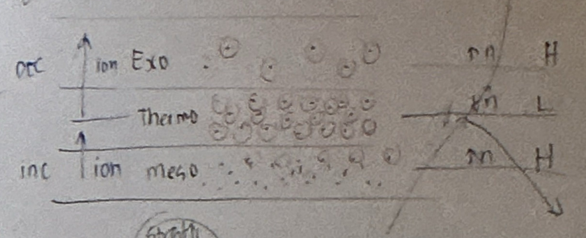
Thermosphere
Layer of the atmosphere where ionization is highest
While the wave is in the HIGHLY DENSE CENTER portion of the layer, refraction occurs more SLOWLY since the density of ionization is almost uniform.
Mesosphere to Thermosphere ionization pattern
Increasing
the Increase in velocity of the upper part of the wave causes it to be BENT BACK TOWARD THE EARTH
Thermosphere to Exosphere ionization pattern
Decreasing
As the wave enters into the upper part of the layer of DECREASING IONIZATION, the velocity of the upper part of the wave decreases, and the wave is BENT AWAY FROM THE EARTH
FREQUENCY OF THE WAVE IN IONOSPHERE
↓ frequency of a radio wave = the more rapidly the wave is refracted by a given degree of ionization = less distance is covered.
ANGLE OF THE WAVE
↓ angle of radiation = longer skip distances as a result of the geometry.
D-layer
The lowest, existing at an average height of 70 km, with an average thickness of 10 km.
Least important layer In HF propagation.
This layer has the ability to refract signals of low frequencies. High frequencies pass right through it and are attenuated.
E-layer / KENELLY-HEAVISIDE LAYER.
Existing at about 100 km in height, with thickness of 25 km.
This layer has the ability to refract signals as high as 20 MHz. For this reason, it is valuable for communications in ranges up to about 1500 miles.
Es-Layer Sporadic
Thin layer of very high ionization density, sometimes making an appearance with the E-layer.
When it occurs, it often persists during the night.
F1-Layer
Exist at a height of 180 km in daytime and combines with the F2 layer at night.
Its daytime thickness is about 20 km.
Main effect is to provide more absorption for HF waves.
F2-Layer
The most important reflecting medium for HF radio waves.
Approximate thickness is 200 km and its height ranges from 250 km to 400 km in daytime. At right, il falls to a height of about 300 km, where it combines with the F1-layer.
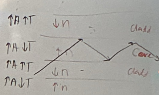
Tropospheric ducting
When the refractive index of the atmosphere drops exceptionally fast with an increase in altitude(often due to a temperature Inversion or rapid moisture changes), signals can become trapped in a narrow layer.
In this propagation method, when the signal encounters a rise In temperature in the atmosphere instead of the normal decreaso (known as a temperature inversion), the higher refractive index of the atmosphere there will cause the signal to be bent.
TROPOSPHERIC SCATTERING
When a radio wave passing through the troposphere meets a turbulence, it makes an abrupt change in velocity. This causes a small amount of the energy to be scattered in a forward direction and returned to Earth at distances beyond the horizon.
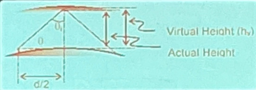
VIRTUAL HEIGHT
The height of the projected path of the Sky Waves.
It is measured by sending a wave vertical to the layer and measuring the time it takes to come back to the receiver.
virtual height > actual height
CRITICAL FREQUENCY
The highest frequency that will be returned down to earth by a certain layer after having been beamed vertically upward.
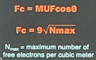
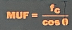
MAXIMUM USABLE FREQUENCY
The highest frequency that will be returned down to the earth at a given distance when beamed at a specific angle other than the normal.
OPTIMUM WORKING FREQUENCY (OWF) / Frequency of Optimum Transmission (FOT) / Optimum Usable Frequency
Frequency chosen by practical to avoid the irregularities of the ionosphere. It is about 15% lower than MUF.

SKIP DISTANCE
The shortest distance from a transmitter, measured along the surface of the earth, at which a sky wave of fixed frequency will be returned to earth.
SKIP ZONE
The area where no signal can be heard.
INTERFERENCE FADING
mixing two or more signal components propagating along different paths
ABSORPTION FADING
caused by solar flare activities and particularly affects the lower frequencies
POLARIZATION FADING
caused by the so-called Faraday Effect or Faraday Rotation
SELECTIVE FADING
fading having different effects on different frequency ranges
11-YEAR SUNSPОТ CYCLE
About every 11 years, the sun's magnetic field does a flip. In other words, the north pole becomes the south pole, and vice versa.
27-DAY SUNSPОТ CYCLE
As the sun rotates on its own axis, these sunspots are visible at 27-day intervals, the approximate period required for the sun to make one complete rotation.
Birefringence / Ionospheric Splitting
When an electromagnetic wave enters the Ionosphere, the Earth's magnetic field splits the single wave into two distinct components with different propagation velocities and polarizations.
SID: Sudden Ionospheric Disturbance
Ionospheric storm causing temporary skywave blackout