062 - Radio Navigation
1/32
There's no tags or description
Looks like no tags are added yet.
Name | Mastery | Learn | Test | Matching | Spaced |
|---|
No study sessions yet.
33 Terms
Terms
Phase/Phase Angle: fraction of one wavelength, expressed in degrees from 0-360˚.
Skip Distance: distance from transmitter, to the point on earth where the first Sky Wave can be received.
Skip Zone/Dead Space: distance between the end of the Ground Wave, and the end of the Skip Distance.
Polarization: Orientation of the plane of oscillation of the electrical component (E) of the electromagnetic wave.
"Sunglasses, Eyes"
Rho/Theta: Rho = Range, Theta = Track (bearing).
QDM = RB + MH.
Reversal Procedures: 45/180, or 80/260.
Night Effect
Ionosphere: part of the sky, high (40-600 km), with electrically charged particles by the Sun.
During day, lower D/E layers will absorb lower (MF/HF) frequencies.
Higher frequencies get through, and get refracted (which causes "reflection") by higher layers.
At night, D dissappears, E weakens, and the lower frequencies will now also get reflected.
This changes the Phase & Polarisation of the received signal.
ITU Classifications
XXX = MSI: Modulation, Signal, Information.
N0N: carrier without modulation, as used by NDBs.
A1A: carrier with keyed Morse code modulation:
BFO makes the carrier audible.
Keying = interrupting the Carrier Wave (on/off).
The bearing indicator is erratic when a NON/A1A station is identifying (due to the on/off!).
A2A: carrier with amplitude modulated Morse:
AM onto the CW.
NDB: use the "regular" ADF function to identify.
A3E: carrier with amplitude modulated Speech used for communication (VHF-COM).
Not used for NDBs!
Wave Propagation
General: Higher frequencies will follow a straight line. Lower frequencies bend and refract more; will follow the Earth.
Ground Waves: surface waves that follow the curvature of the Earth, diffracted along the surface (VLF, LF, MF) (HF very small part).
Sky Waves: (>10 MHz = HF) waves originating from the Earth's surface that are refracted or reflected back to Earth from the ionosphere (at night also MF,
LF- Esp. MF might cause fading with the Ground Wave).Increase Altitude to capture better.
Ionospheric refraction index affects reception.
Space Wave: Line-of-sight EM waves (VHF, UHF, SHF, EHF).
Wavebands
Very Little Men - Have Very Unusual - Sex Experiences.
VLF, LF, MF - HF, VHF, UHF - SHF, EHF.
Starts with a 3: 3 kHz, 3 Mhz, and 3 GHz.
Wavelength (lambda, in m) = 300 / frequency (MHz).
VHF-NAV (VOR) band, 108-117.95 MHz.
Shared VOR and ILS (LOC, odd), 108.0-111.975 MHz.
VHF Range (NM) = 1.23 x (√(H1) + √(H2)).
Propagation Phenomena
Reflection: physical objects/surfaces will reflect back some energy.
VOR mountain effect (multipath).
Diffraction: lines of waves being interrupted by physical objects.
NDB mountain effect.
Refraction: wave bands when passing to another medium.
In the Ionospehere, refraction will cause the wave to bend back to Earth!
Absorption: through a medium, some energy will be lost.
NDBs suffer from terrain absorption.
Attenuation: gradual loss of signal strength over distance.
Antenna Shadowing: due to ACFT shielding.
Fading: interference of the Ground and Sky Wave.
Scalloping: signal bends as a result of reflections from buildings and terrain.
Signal Errors
Quadrantal error (ACFTs metallic structure): NDB/ADF.
Scalloping: VOR. Signal bends as a result of reflections from buildings and terrain.
Night effect: ADF.
Thunderstorm: ADF.
Costal effect: NDB signals bends when crossing the shore line.
Modulation & Antennas
Modulations
Pulse - Radar.
Phase - MLS & GPS.
Amplitude - VHF/HF Comms, ADF, VOR, ILS.
Frequency - Sound broadcasting. Doppler VOR.
Basically everything AM.
Antennas:
Slotted Plannar/Phased Array/Flat Plate: less sidelobes, same beam width.
Directional: Parabolic, Loop, Helical, Slotted Planar Array (Pilots Love Hotels and Sluts!)
RMI & RBI
RMI shows QDM and QDR.
the Compass Card moves.
Gives Magnetic Bearings.
RBI shows RELATIVE BEARING.
QDM = MH + RB.
CDI/HSI
CDI is always relative to the VOR.
CDI can be used with RNAV, will show deviation from programmed courseline.
The HSI will turn with your heading (keep correct image), thus Left/Right will not be relative to the CRS, but to the ACFT.
THE TO/FROM FLAG TURNS AS WELL!
Back-Course: CDI/OBI is always reverse sensing (because only the outside rose turns), HSI will sense correct with Front-Course (opposite) set.
Localizer ONLY, NO glide-path. Non-precision approach.
Establishment
ILS & VOR: within half-scale.
NDB: within ±5° of the required bearing.
ADF also ±5° accuracy
VDF: ±2°.
VOR
Radial = Phase difference between variable and reference signal.
TVOR = Terminal VOR (not Test!), shorter range, part of Approach and Departure structure, usually at airports.
Usually within 108-112 MHz band (112 = terminal ill).
Collocated with DME.
Full Scale = 10˚.
Theta (THrack).
ILS
VHF 108.0-111.975 MHz, odd decimal.
Difference in Depth (DDP) between 90 and 150 Hz modulations. Left to Right.
Glide path:
On UHF. 300 m behind threshold, 120 m from centre line.
Nominal 3˚.
Localizer:
VHF, 300 m behind TORA.
ILS Guidance = half of DH.
ILS full-scale dots: LOC = 2.5˚, GS = 0.7˚.
Markers: all TRANSMIT at 75 MHz (VHF) carrier frequency.
Outer: 4-7 NM, 400 Hz tone, dashes, blue.
Middle: 0.5-0.8 NM, 1300 Hz tone, dots & dashes, amber.
Inner: threshold, 3000 Hz tone, dots, white.
Coverage Area = Critical + Sensitive. Any object within may cause Multipath. For LOC and GP.
Critical = Excluded during All ILS Ops. (I/II/III), Sensitive = All Controlled (forbidden when II/III).
“defined area around LOC/GP…”
Warning Flag: absence of carrier/modulation, modulation reduced to 0.
ILS + GBAS Coverage Areas
GP: 8˚ & 10 NM (18 to glide in).
+ angular coverage: BMW 135, 525, i8.
ILS Loc: 10˚ & 25 NM OR 35˚ & 17 NM.
17 * 2 = 35, -10 = 25.
GBAS: 15 NM 35˚ / 20 NM 10˚.
35 - 15 = 20.
Station range = ~20.
1535, Luther Reformation.
DME
UHF: 960-1215 MHz. Often paired with VOR. Rho (RHange).
Max 100 interrogations, strongest signals.
50 micro-seconds delay (10-6).
c = 300.000 km/s.
Signal Lost: "Memory Mode" - DME range keeps changing at the same rate for 8-10s.
Interrogation (ACFT) is randomised in a Unique Rhythm, to distinguish for own reply.
Magic words: “Position Line” = ground distance.
Any other case it is SLANT RANGE!
Collocated VOR/ILS/DME
Ident DME: 1 every 40 seconds. Higher pitched tone.
Ident VOR/ILS: 3 times per 40 seconds.
NDB
LF-MF, 190-1750 KHz. Picked up by ADF.
Locator = lower powered NDB. 10-25 NM range.
2x Range = 4x Power.
BFO for hearing the N0N A1A morse carrier wave (usually automatic).
3 letters en-route, 2/1 letter terminal.
ADF for A2A.
Over Sea better range! Less ground absorption.
MLS
SHF (5.03-5.09 GHz), 200 channels.
Components: Azimuth (Front & Back), Elevation Guidance, DME/P (for 3D position: segmented/curved), Data-comms.
Time between To/From scans in Azimuth and Elevation determines ACFT postition.
20 NM, 40˚. (420, MiLfS +/- 40).
Primary Surveillance Radar
Max Range (km): 300.000 / (PRF x 2). Reduce PRF for more range.
Min Range (km): (300.000 * Pulse Length) / 2. (Your length is minimum).
Range NM: 4sqrt(Watt). Double range = 16x power.
Practical Range (en-route surveilance): 200-300 NM (PRF = 270).
Pulse Power = Peak Power.
Azimuth = Beam Width.
Secondary Surveillance Radar
Transmits 1030 MHz, Receives 1090 MHz.
Spacing between P1 and P3 pulse determines Mode.
All Call (acquiring new): Short P4 = A/C, Long P4 = A/C/S.
P2 for Side Lobe Suppression (SLS).
Mode S = Selective Addressing (via P4).
S = P1, P3 and P4.
Mode A: code 0 to 7.
"IDENT" = SPI. “ALT” = A+C+S. “ON” = A only.
Mode S(mall): 25 ft, Mode C(entury): 100 ft.
Airborne Weather Radar
SHF, 9.375 GHz (9375 MHz), 3 cm.
Can also scan the Ground to obtain relative (/magnetic) bearings.
Keyword: Mapping Mode, suitable echoes.
Pitch & Roll stabilised. Not Yaw.
Slotted Planar:
Conical (pencil) = for Far.
Cosecant (squared) = Close (~60 NM).
Weather = Conical, Ground = Cosecant/both.
Flat Plate:
Ground = Conical/Pencil.
Map: A Flat Pencil, A Slotted Cosecant.
Storm: tilt up for T/O, tilt down for Cruise. Decrease during Climb.
GNSS
Over UHF.
L1: C/A (civilian) & P-codes (military).
L2: only P-codes.
Combining eliminates Ionospheric.
Total position error = UERE x GDOP.
Greatest Errors: Ionospheric Delays. After that: GDoP.
NAVSTAR: 24 sats., 6 orbits, 20.180 km.
Control: master control station, ground antenna, monitoring station.
Nav-message: sat. clock correction, UTC, ionospheric model, health.
GLONASS: 24, 3, 19.099 km.
Galileo: 30, 3, 23.222 km.
2 independent, non-identical clocks, not synchronised.
GNSS Augmentation (SBAS & GBAS)
Both use ground stations.
SBAS transmits to a geostationary satellite via UHF.
GBAS transmits to the ACFT directly, via VHF-Datalink.
Corrects for any of the GPS errors. Not for ACFT receiver errors!
GBAS enables GLS = PA approach.
SBAS enables LPV = NPA.
New: SBAS LPV CAT 1 = PA.
GBAS needs at least 4 satellites. SBAS up to 4.
SBAS: 2 elements: ground + satellites. 3 segments: ground, space, user.
Airborne-based Augmentation System
ABAS = AAIM + RAIM.
A AIM = Aircraft Autonomous: GNSS integrity, based on other (redundant) internal systems (IRS, Barometer).
RAIM: purely Satellite based, using an extra satellite to check the working of the usual 4 required (for 3D).
5 for Fault Detection, 6 for Exclusion.
May use a approved barometer.
PBN
PBN = RNP & RNAV
RNAV & conventional = Sensor Specific (raw data), RNP = not (computed).
RNP APCH, 3 ways, 3 minima:
LNAV: just Lateral, 2D.
LNAV/VNAV: with vertical = 3D. Lower minima.
Baro-VNAV: has temperature limits, or temperature correction during the FAS.
Pilots apply corrections on almost all altitudes. Automatic System on FAS only!
or SBAS (is backwards capable).
LPV: Vertical with SBAS, 3D. Must have FAS datablock. Close to CAT 1 minima (LPV minima).
Law: PBN = only certain specification require approval, RNP = Operator dependent.
FRT/RF/Turns
You can FRT in cruise, but not during approach.
FRT - Fixed Radius Turn: either 22.5 (>FL195) or 15 NM radius.
RF - Radius to Fix: a continuous curve between two waypoints.
Curved Terminal/Approach section, defined by Fix, Radius and Arc-length.
Fly-by/Over: only Fly-by allowed in RNP tracks.
PBN 2
Application (SID/STAR), Infrastructure (GNSS), Specification (RNAV/RNP).
Availability: Percentage of time when available for use.
Accuracy: True Position.
Integrity: Trust we can hold in a system.
Continuity: Working without interruptions.
Functionality: Required functions.
PBN Specifications
Number = the lateral navigation accuracy in NM (on both sides), which is expected to be achieved >95% of the flight time.
RNAV 10 = RNP 10.
NAT HLA = Oceanic. RNAV 10 (RNP 10) and RNP 4. Sometimes RNP 2.
RNAV & RNP 1, 2:
Manual Waypoint insertion/creation NOT permitted.
Route modification on ATC only.
RNAV 5: manual Waypoint insertion IS permittable.
PBN Errors
PBN Errors
TSE is the Actual Total Error, EPE/ANP (Airbus/Boeing) is the Estimated Total Error.
PDE = Path Definition Error, considered 0.
NSE = Navigation System Error.
FTE = Flight Technical Error (Crew or A/P ability to follow path).
FTE and NSE can be monitored by the ACFT
PDE cannot be monitored, as it is a error of the data itself.
PBN Specifications, Advanced
Advanced-RNP: RNAV521 RNP21 APCH.
RNP 1 & 0.3: helicopter.
RNP 2 is Continental and Oceanic.
RNAV & RNP 1: for terminal phases (SIDs, STARs)
RNAV 2: C-A-D. (cont., arr., dept.).
RNAV 10 (RNP 10), RNP 4 & 2: Oceanic.
RNAV 5: arrival, enroute continental (>30 NM, above MSA).
PBN Specs. short
RNAV 10 - oceanic
RNAV 5 - enroute/arrival
RNAV 2 - enroute/arrival/departure
RNAV 1 - arrival/departure
--
RNP4 - oceanic
RNP2 -enroute
RNP1 - arrival departure (is the same as RNAV1)
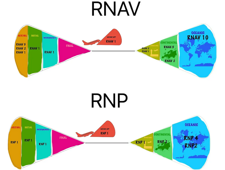
RNAV & RNP picture
Arrival, Initial, Intermediate, Final (no), Departure, Continental, Oceanic.
RNAV: 125, 1, 1, - , 12, 25, 10.
RNP: 1, 1, 1, -, 1, 2, 24.
Type A & B
Type A: >250 DH.
Type B(elow): <250 DH.
CAT I: >200, Vis. >800 m/RVR >550 m.
CAT II: >100, RVR >300 m.
CAT III: <100/0, RVR<300/0 m.
FAF = NPA, FAP = PA.
Point in space is more accurate.