Fund. of Electricity Figures

0.0(0)
studied byStudied by 0 people
GameKnowt Play
learnLearn
examPractice Test
spaced repetitionSpaced Repetition
heart puzzleMatch
flashcardsFlashcards
Card Sorting

1/36

encourage image

There's no tags or description

Looks like no tags are added yet.

Study Analytics
Name
Mastery
Learn
Test
Matching
Spaced

No study sessions yet.

37 Terms

1
New cards
<p>(<span style="color: rgb(0, 0, 0);"><mark data-color="#edff00" style="background-color: rgb(237, 255, 0); color: inherit;"><u>Refer to Figure 1.</u></mark></span>) When different rated capacitors are connected in series in a circuit, the total capacitance is</p>

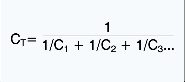
(Refer to Figure 1.) When different rated capacitors are connected in series in a circuit, the total capacitance is

Less than capacitance of the lowest rated capicator

2
New cards
<p>(<span style="color: rgb(0, 0, 0);"><mark data-color="#fffc00" style="background-color: rgb(255, 252, 0); color: inherit;">Refer to Figure 2.</mark></span>) What is the total capacitance of a circuit containing three capacitors with capacitances of .02 microfarad, .05 microfarad, and .10 microfarad, respectively?</p>

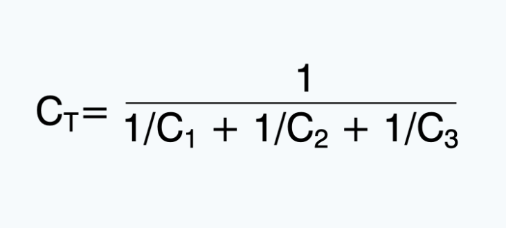
(Refer to Figure 2.) What is the total capacitance of a circuit containing three capacitors with capacitances of .02 microfarad, .05 microfarad, and .10 microfarad, respectively?

0.125uF

3
New cards
<p>(<span style="color: rgb(0, 0, 0);"><mark data-color="#fffc00" style="background-color: rgb(255, 252, 0); color: inherit;">Refer to Figure 3.</mark></span>) When more than two inductors of different inductances are connected in parallel in a circuit, the total inductance is</p>

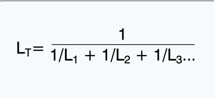
(Refer to Figure 3.) When more than two inductors of different inductances are connected in parallel in a circuit, the total inductance is

Less than the inductance of the lowest rated inductor

4
New cards
<p>(<span style="color: rgb(0, 0, 0);"><mark data-color="#f1e100" style="background-color: rgb(241, 225, 0); color: inherit;">Refer to Figure 5.</mark></span>) What is the impedance of an ac-series circuit consisting of an inductor with a reactance of 10 ohms, a capacitor with a reactance of 4 ohms, and a resistor with a resistance of 8 ohms?</p>

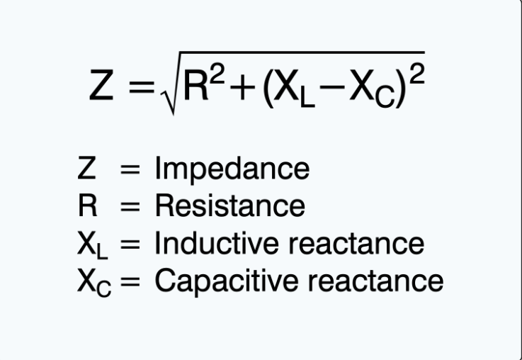
(Refer to Figure 5.) What is the impedance of an ac-series circuit consisting of an inductor with a reactance of 10 ohms, a capacitor with a reactance of 4 ohms, and a resistor with a resistance of 8 ohms?

10 Ohms

5
New cards
<p>(<span style="color: rgb(0, 0, 0);"><mark data-color="#fff508" style="background-color: rgb(255, 245, 8); color: inherit;">Refer to Figure 9.</mark></span>) How many instruments (voltmeters and ammeters) are installed correctly?</p>

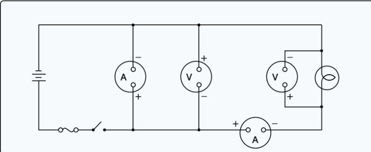
(Refer to Figure 9.) How many instruments (voltmeters and ammeters) are installed correctly?

Two

6
New cards
<p>(<span style="color: rgb(0, 0, 0);"><mark data-color="#f8f506" style="background-color: rgb(248, 245, 6); color: inherit;">Refer to Figure 10.</mark></span>) What is the measured voltage of the series-parallel circuit between terminals A and B?</p>

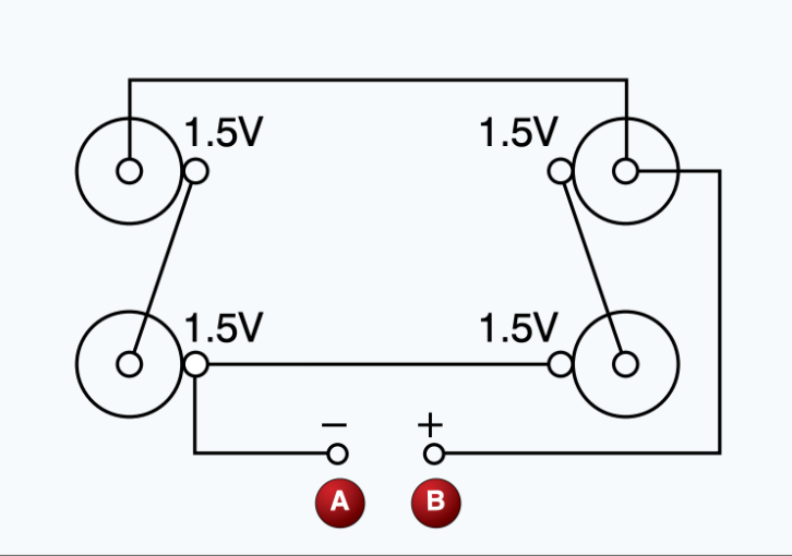
(Refer to Figure 10.) What is the measured voltage of the series-parallel circuit between terminals A and B?

3 Voltz

7
New cards
<p>(<span style="color: rgb(0, 0, 0);"><mark data-color="#f6f309" style="background-color: rgb(246, 243, 9); color: inherit;">Refer to Figure 11.</mark></span>) Find the voltage across the 8-ohm resistor.</p>

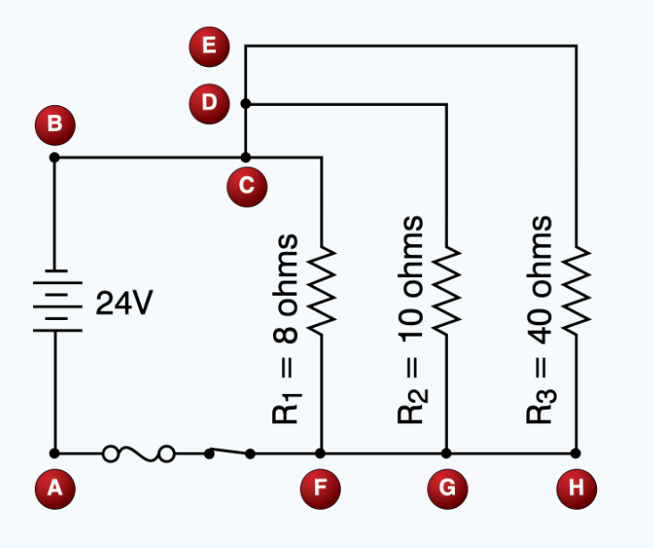
(Refer to Figure 11.) Find the voltage across the 8-ohm resistor.

24 Voltz

8
New cards
<p>(<span style="color: rgb(0, 0, 0);"><mark data-color="#dff002" style="background-color: rgb(223, 240, 2); color: inherit;">Refer to Figure 22.</mark></span>) Which illustration is correct concerning bias application and current (positive charge) flow?</p>

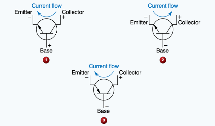
(Refer to Figure 22.) Which illustration is correct concerning bias application and current (positive charge) flow?

1

9
New cards
<p>(<span style="color: rgb(0, 0, 0);"><mark data-color="#f6f908" style="background-color: rgb(246, 249, 8); color: inherit;">Refer to Figure 11.</mark></span>) Find the total current flowing in the wire between points C and D.</p>

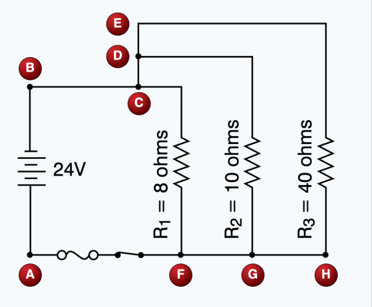
(Refer to Figure 11.) Find the total current flowing in the wire between points C and D.

3 Amps

10
New cards
<p>(<span style="color: rgb(0, 0, 0);"><mark data-color="#e2fa00" style="background-color: rgb(226, 250, 0); color: inherit;">Refer to Figure 13.</mark></span>) Determine the total current flow in the circuit.</p>

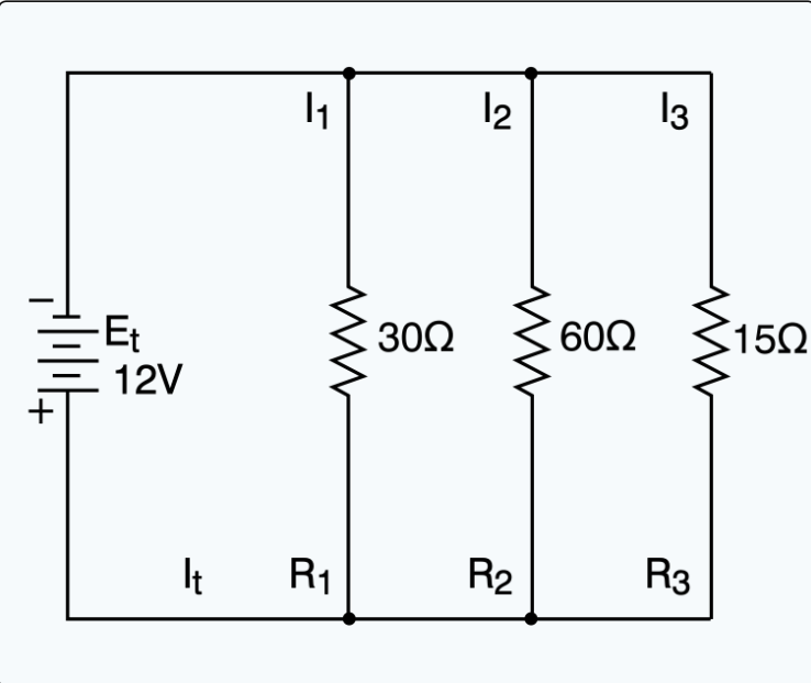
(Refer to Figure 13.) Determine the total current flow in the circuit.

1.4 amps

11
New cards
<p>(<span style="color: rgb(0, 0, 0);"><mark data-color="#fffc00" style="background-color: rgb(255, 252, 0); color: inherit;">Refer to Figure 64.</mark></span>) A 24-volt source is required to furnish 48 watts to a parallel circuit consisting of two resistors of equal value. What is the value of each resistor?<br>(Note: R(t) = E^2/P)</p>

(Refer to Figure 64.) A 24-volt source is required to furnish 48 watts to a parallel circuit consisting of two resistors of equal value. What is the value of each resistor?
(Note: R(t) = E^2/P)

24 ohms

12
New cards
<p>(<span style="color: rgb(0, 0, 0);"><mark data-color="#f9f004" style="background-color: rgb(249, 240, 4); color: inherit;">Refer to Figure 12.</mark></span>) Find the total resistance of the circuit.</p>

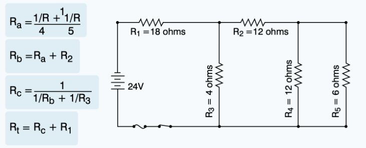
(Refer to Figure 12.) Find the total resistance of the circuit.

21.2 Ohms

13
New cards
<p>(<span style="color: rgb(0, 0, 0);"><mark data-color="#fffc00" style="background-color: rgb(255, 252, 0); color: inherit;">Refer to Figure 14.</mark></span>) The total resistance of the circuit is</p>

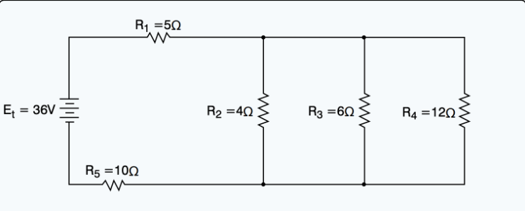
(Refer to Figure 14.) The total resistance of the circuit is

17 Ohms

14
New cards
<p>(<span style="color: rgb(0, 0, 0);"><mark data-color="#f4ff00" style="background-color: rgb(244, 255, 0); color: inherit;">Refer to Figure 64.</mark></span>) A 48-volt source is required to furnish 192 watts to a parallel circuit consisting of three resistors of equal value. What is the value of each resistor?</p>

(Refer to Figure 64.) A 48-volt source is required to furnish 192 watts to a parallel circuit consisting of three resistors of equal value. What is the value of each resistor?

36 Ohms

15
New cards
<p>(<span style="color: rgb(0, 0, 0);"><mark data-color="#ffe000" style="background-color: rgb(255, 224, 0); color: inherit;">Refer to Figure 6.</mark></span>) If resistor R(5) is disconnected at the junction of R(4) and R(3) as shown, what will the ohmmeter read?</p>

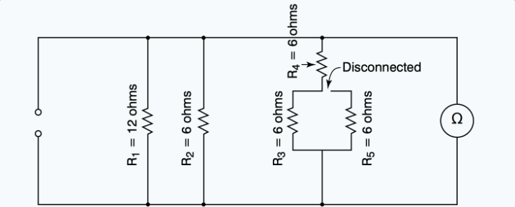
(Refer to Figure 6.) If resistor R(5) is disconnected at the junction of R(4) and R(3) as shown, what will the ohmmeter read?

3 Ohms

16
New cards
<p>(<span style="color: rgb(0, 0, 0);"><mark data-color="#ffee00" style="background-color: rgb(255, 238, 0); color: inherit;">Refer to Figure 7.</mark></span>) If resistor R(3) is disconnected at terminal D, what will the ohmmeter read?</p>

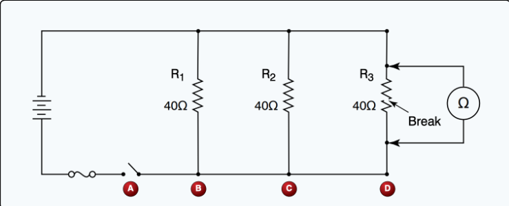
(Refer to Figure 7.) If resistor R(3) is disconnected at terminal D, what will the ohmmeter read?

Inf Resis

17
New cards
<p>(<span style="color: rgb(0, 0, 0);"><mark data-color="#fbff00" style="background-color: rgb(251, 255, 0); color: inherit;">Refer to Figure 8.</mark></span>) With an ohmmeter connected into the circuit as shown, what will the ohmmeter read?</p>

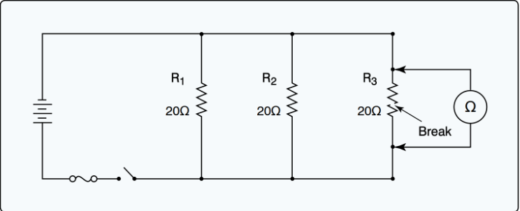
(Refer to Figure 8.) With an ohmmeter connected into the circuit as shown, what will the ohmmeter read?

10 Ohms

18
New cards
<p>(<span style="color: rgb(0, 0, 0);"><mark data-color="#efec00" style="background-color: rgb(239, 236, 0); color: inherit;">Refer to Figure 4.</mark></span>) How much power is being furnished to the circuit?</p>

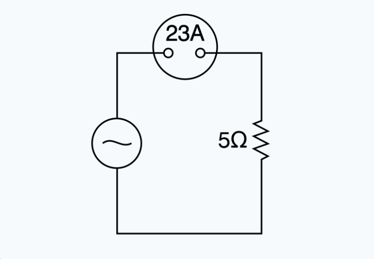
(Refer to Figure 4.) How much power is being furnished to the circuit?

2,645 Watts

19
New cards
<p>(<span style="color: rgb(0, 0, 0);"><mark data-color="#edff00" style="background-color: rgb(237, 255, 0); color: inherit;">Refer to Figure 24.</mark></span>) Which statement concerning the depicted logic gate is true?</p>

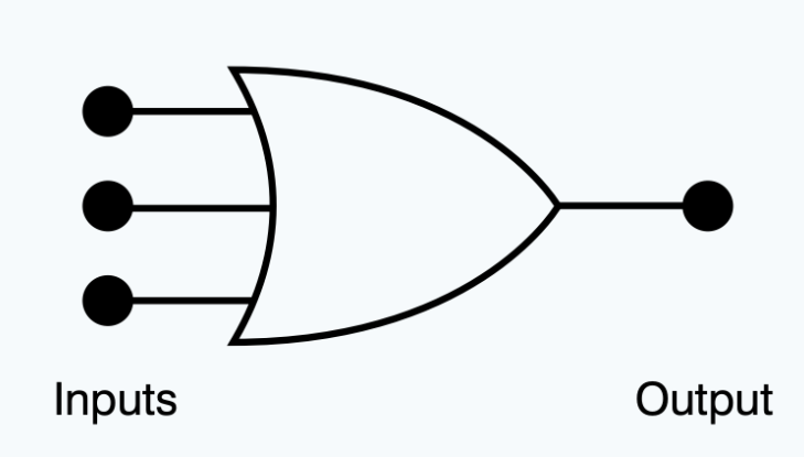
(Refer to Figure 24.) Which statement concerning the depicted logic gate is true?

ANY INPUT 1 = 1 OUTPUT

20
New cards
<p>(<span style="color: rgb(0, 0, 0);"><mark data-color="#fffc00" style="background-color: rgb(255, 252, 0); color: inherit;">Refer to Figure 25.</mark></span>) In a functional and operating circuit, the depicted logic gate's output will be 0</p>

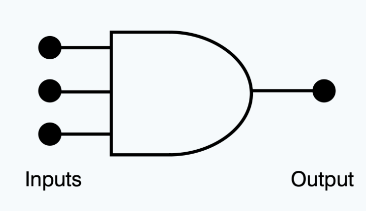
(Refer to Figure 25.) In a functional and operating circuit, the depicted logic gate's output will be 0

When one or more inputs are 0

21
New cards
<p>(<span style="color: rgb(0, 0, 0);"><mark data-color="#fffc00" style="background-color: rgb(255, 252, 0); color: inherit;">Refer to Figure 26.</mark></span>) Which of the logic gate output conditions is correct with respect to the given inputs?</p>

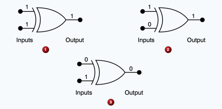
(Refer to Figure 26.) Which of the logic gate output conditions is correct with respect to the given inputs?

2

22
New cards
<p>(<span style="color: rgb(0, 0, 0);"><mark data-color="#ffee00" style="background-color: rgb(255, 238, 0); color: inherit;">Refer to Figure 15.</mark></span>) Wire 7 is used to</p>

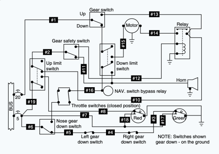
(Refer to Figure 15.) Wire 7 is used to

PUSH-TO-TEST

23
New cards
<p>(<span style="color: rgb(0, 0, 0);"><mark data-color="#e3fa03" style="background-color: rgb(227, 250, 3); color: inherit;">Refer to Figure 15.</mark></span>) When the landing gear is down, the green light will not come on if an open occurs in wire</p>

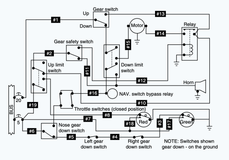
(Refer to Figure 15.) When the landing gear is down, the green light will not come on if an open occurs in wire

6

24
New cards
<p>(<span style="color: rgb(0, 0, 0);"><mark data-color="#edff00" style="background-color: rgb(237, 255, 0); color: inherit;">Refer to Figure 16.</mark></span>) What will be the effect if the PCO relay fails to operate when the left-hand tank is selected?</p>

(Refer to Figure 16.) What will be the effect if the PCO relay fails to operate when the left-hand tank is selected?

open light will NOT illuminate

25
New cards
<p>(<span style="color: rgb(0, 0, 0);"><mark data-color="#fffc00" style="background-color: rgb(255, 252, 0); color: inherit;">Refer to Figure 16.</mark></span>) The TCO relay will operate if 24-volts DC is applied to the bus and the fuel tank selector is in the</p>

(Refer to Figure 16.) The TCO relay will operate if 24-volts DC is applied to the bus and the fuel tank selector is in the

crossfeed

26
New cards
<p>(<span style="color: rgb(0, 0, 0);"><mark data-color="#fbff00" style="background-color: rgb(251, 255, 0); color: inherit;">Refer to Figure 16.</mark></span>) When electrical power is applied to the bus, which relays are energized?</p>

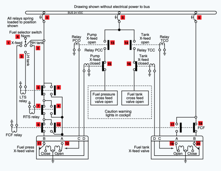
(Refer to Figure 16.) When electrical power is applied to the bus, which relays are energized?

PCC/TCC

27
New cards
<p>(<span style="color: rgb(0, 0, 0);"><mark data-color="#fffc00" style="background-color: rgb(255, 252, 0); color: inherit;">Refer to Figure 16.</mark></span>) Energize the circuit with the fuel tank selector switch selected to the left-hand position. Using the schematic, identify the switches that will change position.</p>

(Refer to Figure 16.) Energize the circuit with the fuel tank selector switch selected to the left-hand position. Using the schematic, identify the switches that will change position.

5,6,11,12,13,15, and 16

28
New cards
<p>(<span style="color: rgb(0, 0, 0);"><mark data-color="#e7ff00" style="background-color: rgb(231, 255, 0); color: inherit;">Refer to Figure 17.</mark></span>) Which of the components is a potentiometer?</p>

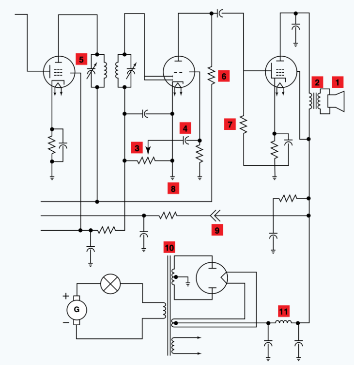
(Refer to Figure 17.) Which of the components is a potentiometer?

3

29
New cards
<p>(<span style="color: rgb(0, 0, 0);"><mark data-color="#edff00" style="background-color: rgb(237, 255, 0); color: inherit;">Refer to Figure 17.</mark></span>) The electrical symbol represented at number 5 is a variable</p>

(Refer to Figure 17.) The electrical symbol represented at number 5 is a variable

Capacitor

30
New cards
<p>(<span style="color: rgb(0, 0, 0);"><mark data-color="#fffc00" style="background-color: rgb(255, 252, 0); color: inherit;">Refer to Figure 18.</mark></span>) When the landing gear is up and the throttles are retarded, the warning horn will not sound if an open occurs in wire</p>

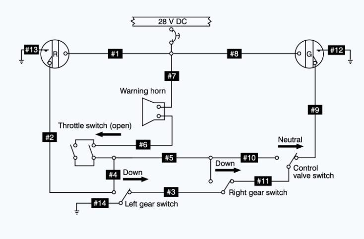
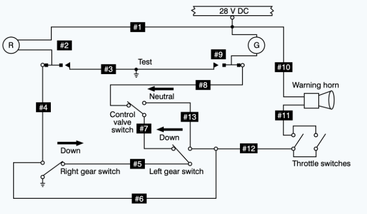
(Refer to Figure 18.) When the landing gear is up and the throttles are retarded, the warning horn will not sound if an open occurs in wire

4

31
New cards
<p>(<span style="color: rgb(0, 0, 0);"><mark data-color="#d9ff00" style="background-color: rgb(217, 255, 0); color: inherit;">Refer to Figure 18.</mark></span>) The control valve switch must be placed in the neutral position when the landing gear is down to</p>

(Refer to Figure 18.) The control valve switch must be placed in the neutral position when the landing gear is down to

Prevent warning horn from sounding

32
New cards
<p>(<span style="color: rgb(0, 0, 0);"><mark data-color="#edff00" style="background-color: rgb(237, 255, 0); color: inherit;">Refer to Figure 19.</mark></span>) Under which condition will a ground be provided for the warning horn through both gear switches when the throttles are closed?</p>

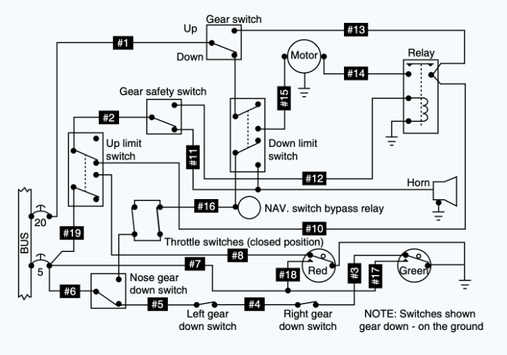
(Refer to Figure 19.) Under which condition will a ground be provided for the warning horn through both gear switches when the throttles are closed?

Left up , Right down

33
New cards
<p>(<span style="color: rgb(0, 0, 0);"><mark data-color="#fbff00" style="background-color: rgb(251, 255, 0); color: inherit;">Refer to Figure 19.</mark></span>) When the throttles are retarded with only the right gear down, the warning horn will not sound if an open occurs in wire</p>

(Refer to Figure 19.) When the throttles are retarded with only the right gear down, the warning horn will not sound if an open occurs in wire

5

34
New cards
<p>(<span style="color: rgb(0, 0, 0);"><mark data-color="#fffc00" style="background-color: rgb(255, 252, 0); color: inherit;">Refer to Figure 19.</mark></span>) When the landing gears are up and the throttles are retarded, the warning horn will not sound if an open occurs in wire</p>

(Refer to Figure 19.) When the landing gears are up and the throttles are retarded, the warning horn will not sound if an open occurs in wire

6

35
New cards
<p>(<span style="color: rgb(0, 0, 0);"><mark data-color="#e0ff00" style="background-color: rgb(224, 255, 0); color: inherit;">Refer to Figure 23.</mark></span>) If an open occurs at R(1), the light</p>

(Refer to Figure 23.) If an open occurs at R(1), the light

Can't be turned off

36
New cards
<p>(<span style="color: rgb(0, 0, 0);"><mark data-color="#ffee00" style="background-color: rgb(255, 238, 0); color: inherit;">Refer to Figure 23</mark></span>.) If R(2) sticks in the up position, the light will</p>

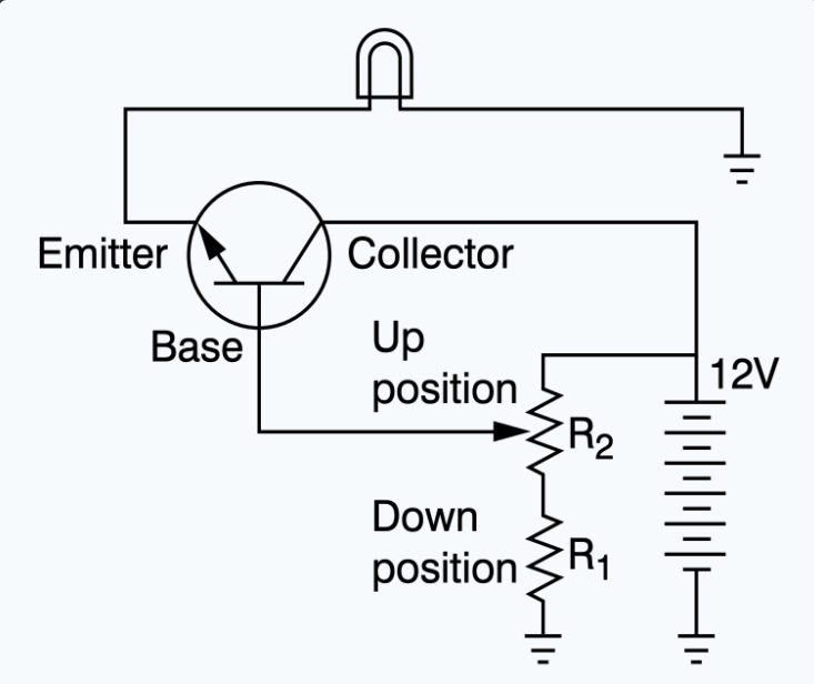
(Refer to Figure 23.) If R(2) sticks in the up position, the light will

be on full bright

37
New cards
<p>(<span style="color: rgb(0, 0, 0);"><mark data-color="#edff00" style="background-color: rgb(237, 255, 0); color: inherit;">Refer to Figure 15.</mark></span>) With the landing gear retracted, the red indicator light will not come on if an open occurs in wire</p>

(Refer to Figure 15.) With the landing gear retracted, the red indicator light will not come on if an open occurs in wire

19