FG-02 Power Plant and Fuel Systems
1/23
There's no tags or description
Looks like no tags are added yet.
Name | Mastery | Learn | Test | Matching | Spaced | Call with Kai | Chat |
|---|
No analytics yet
Send a link to your students to track their progress
24 Terms
Power plant takeoff power
Normal Take-off Power 1800 hp (2000 hp emergency up-trim)
Propeller description
Hamilton Standard 14-SF four-blade, feathering, reversible constant speed unit.
Power plant operation
managed by Power Levers and Condition Levers in the Flight Compartment
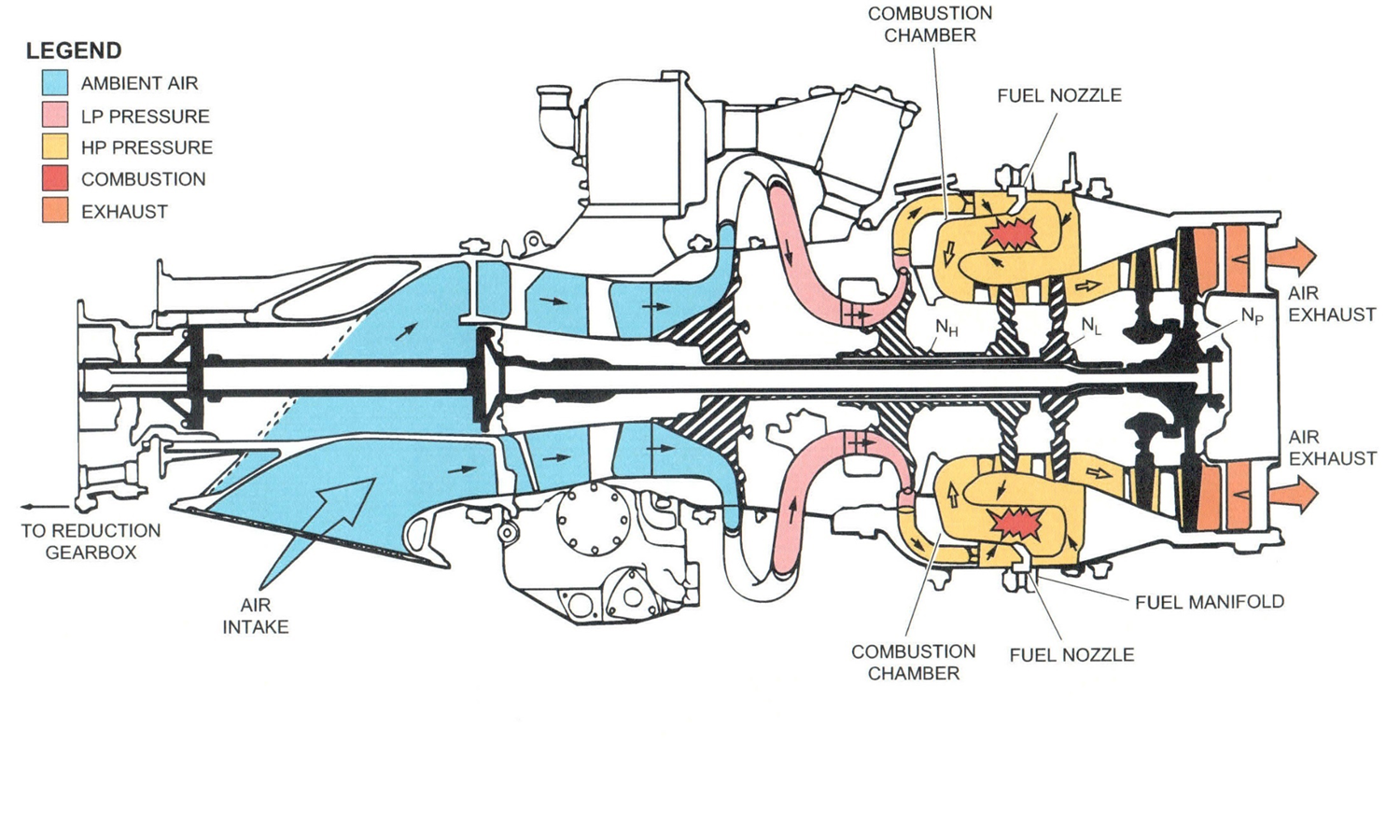
Power Plant Diagram
Power Levers
Controls engine speed & propeller pitch in ground operation & during Approach and Landing (Beta mode)
Condition Levers
Set propeller RPM during flight (constant speed mode) (min 900 max 1200 RPM)
Auto Feather System
- Provides automatic prop feathering following an engine failure during take off and engine up-trim for the unaffected engine.
- Feathered to reduce drag, and control the rotation of the free spinning prop
Power up-trim mode
Automatically boosts power output of one engine (2000 hp) in response to auto feathering of the opposite engine during take-off
Propeller syncrophase system
Synchronizes both propeller speed and blade position of the two propellers in cruise flight.
Significant noise and vibration reduction to increase crew comfort.
Matches the speed and phase of the No.2 propeller (slave) to that of the No. 1 Prop (master).
Engine oil system
- Provides lubrication of engine bearings and gear boxes
- Provides oil pressure for propeller actuation.
- Pressurized by pressure pump driven by accessory gearbox. (60 psi)
- Cooled by oil cooler (75-85 C)
Power plant monitoring
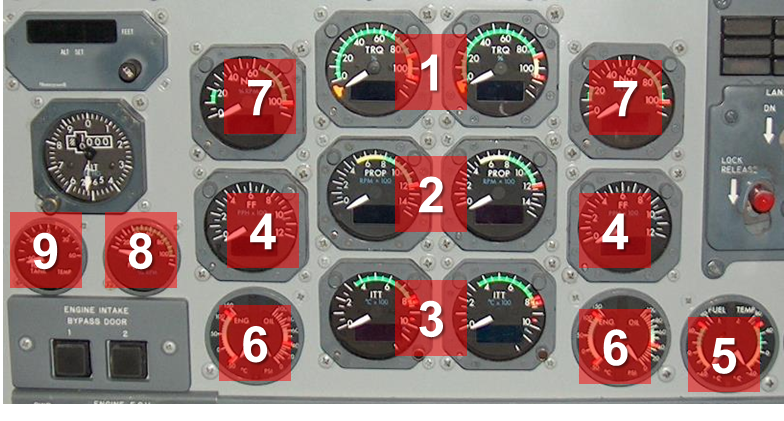
Engine torque
Propeller RPM
Inter-Turbine Temperature (ITT)
Fuel flow
Fuel temperature
Oil temp and pressure
NH (High pressure compressor speed)
NL (Low pressure compressor speed)
Fuel tank temperature
Main fuel tanks
Located on the outboard side of the nacelle. Each also contain a Collector and Surge bay.
There are 3 pumps per main tank. One to pump fuel out of the collector bay into the engines and two to pump fuel into the collector bays.
Collector bays
Gravity fed from the Main tank through one-way check valves, topped up by a high-volume pumping system. This ensures the collector bay is full at all times in order to supply the engines. Excess fuel spills over the top of a divider back into the Main Tanks.
Surge bays
Facilitate Main and Aux tank venting during fueling and fuel transfers. Does not normally contain any fuel. Any fuel that does make it to the surge bay is returned to the main tanks via ram air pressure provided by vents in the wings.
Aux tanks
A single scavenge pump transfers fuel into the associated main tank. Are NOT capable of feeding directly into the collector bay or across into the opposite wings tanks.
Usable main tanks fuel
5678 lbs
Usable aux tanks fuel
4566 lbs
Total usable fuel
10244 lbs
Max fuel with 8 crew
6780 lbs
Fuel transfer system
Aux tanks to associated main tanks, between main tanks
To correct any fuel imbalances, fuel is pumped from one main tank to the other.
Max fuel imbalance allowed
Main tanks: up to 600 lbs
Aux tanks: up to 1500 lbs
If the aux tanks are max imbalanced, the main tanks are allowed no imbalance, and vice-versa
Standard fuel
JP8+100
F37
Acceptable fuels
Jet A
Jet B'
Jet A1
JP4
JP5
JP8
Emergency fuels
AVGAS
F22