EPPT: Virtual Session #1
1/49
There's no tags or description
Looks like no tags are added yet.
Name | Mastery | Learn | Test | Matching | Spaced |
|---|
No study sessions yet.
50 Terms
What are two navigation modes offered in Ensite X EP System?
What mapping systems can accommodate both modes?
VoXel Mode (magnetic field) and NavX mode (impedance field)
VoXel Mode → procedural stability in various cases, ranging from AF to VT
Only Abbott Ensite X

Two elements of a navigation mode and how each is generated in NavX versus VoXel
Coordinate system
NavX: 6 locating electrodes
VoXel: PRS-P and PRS-A sensors
Electroanatomical 3D space
NavX: Human body with various baseline impedances = impedance field
VoXel: Field frame - generates magnetic field
What is the human bioelectrical impedance? Why is our impedance system considered dynamic?
Impedance ranges from 150 to 900 ohms. Dynamic because our body is composed of different tissues (i.e. nervous, connective, cardiac, etc) and fluids (air, blood, etc) with different resistances to electrical current. Changes in fluid volume, systole/diastole, creation of scar tissue, etc. all lead to fluctuating system impedances
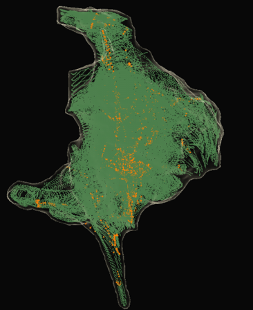
What kind of data points are collected by catheter electrodes in…
NavX Mode? And how are structures visualized?
VoXel Mode?
Impedance data points (GREEN) - we can visualize structures due to local changes in thoracic impedance. See electrodes in impedance field
*Orange points are SE points (magnetic data from magnetic sensor)
Magnetic data points (BLUE)

What is the purpose of NavX (SE) Field Scaling?
NavX Field Scaling: To linearize the impedance data by scaling our model based on the location of electrodes, and thereby improve the accuracy of the anatomic model. We use this since the body does not stay in a static condition, so visualization in NavX Mode may be compromised.
NavX SE Field Scaling: To provide additional model and catheter correction using secondary magnetic data, as long as the catheter is an SE catheter, we are working in a magnetic field, and we’ve collected SE points (ORANGE). Compensates for non-linearity of the impedance field
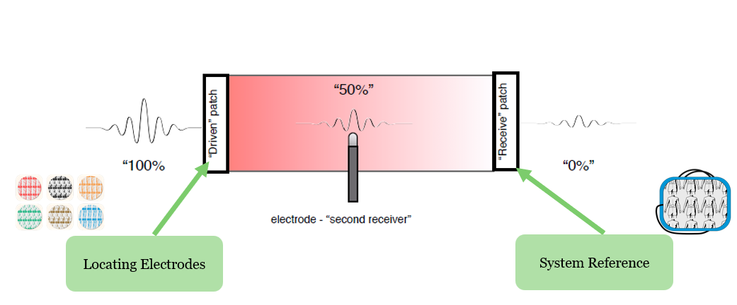
How do we generate an impedance field, and when does it become active?
Place 6 locating electrodes on patient, 3 sets at 180 degrees from each other.
*Current from Ensite X Amplifier → locating electrodes → current travels through body → system reference patch as primary receiver (ground), electrode as secondary receiver (picks up on local impedance changes in response to current)
We generate current and set baseline impedance when we VALIDATE the system - bioimpedance scaling, accounting for patient weight and patch placement
What sensors create the impedance field and coordinate system? What is the origin?
The 6 locating electrodes create xyz coordinate system. Origin is the intersection of these mapping patches, ideally at the heart
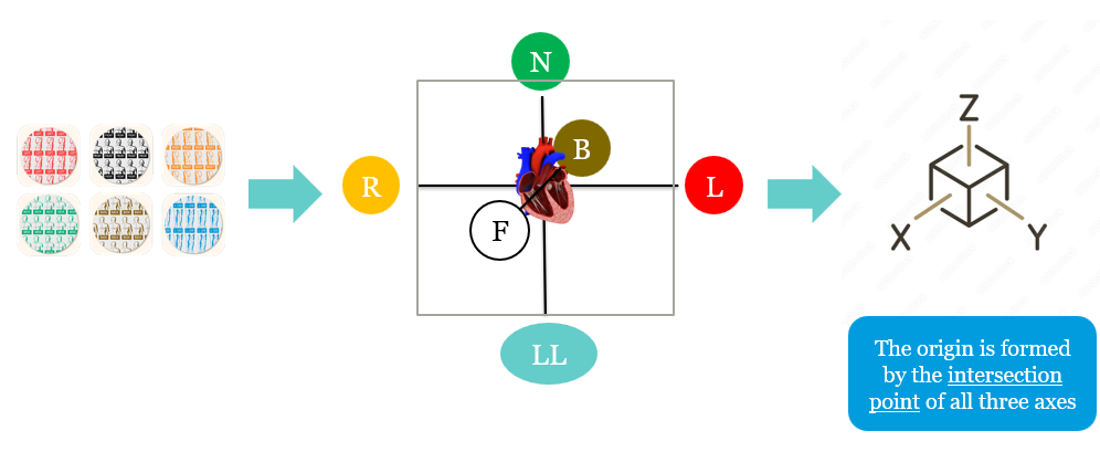
Where do we place the different-colored locating electrodes?
Red
Black
Orange
Green
Brown
Blue
Red = left
Black = front
Orange = right
Green = neck
Brown = back
Blue = left leg
Why do we experience visualization distortion with NavX Mode?
Because the body has a dynamic impedance field, so the system’s understanding of catheter placement will shift as impedance changes
Describe four key factors that impact an impedance-based system. Others?
Baseline versus arrhythmic state - think cardioversion, altering arrhythmic state - changes BP and blood volumes
Guidewires - metal introduction, devices in the body
Bodily fluids
Respiration
*Others: patient movement, patch movement, EMI, ablation
Describe when model/mapping data can be collected and when catheters can be visualized in NavX Mode:
Standard catheters
Sensor Enabled tools
Data collection - always, visualization - always
Data collection - always, visualization - always
Two KEY features associated with NavX Mode
Flexible workflows with 3rd party catheters
Minimal fluoroscopy usage required
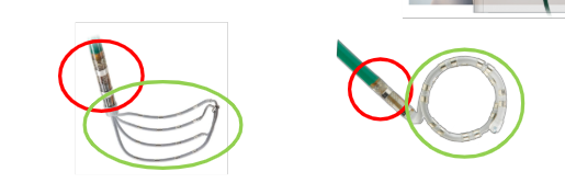
Describe the construction of the proximal and distal ends of an SE catheter and what types of data they collect and/or need to be visualized
Proximal RIGID end = shaft with magnetic sensor, collects VoXels (impedance fiducials, points that link magnetic and impedance data). Visualized based on magnetic data.
Distal FLEXIBLE end = paddle or loop, visualized based on impedance and magnetic data, so requires VoXel points to be visualized and to collect data
Low confidence versus high confidence states for SE tools
Low confidence = only SE shaft (and proximal electrodes) are visualized and can collect 3D data and VoXels due to low-density VoXel clouds. The remaining electrodes are grayed out.
*Note: Standard catheters cannot collect data in VoXel Mode.
High confidence = all electrodes are visualized and can collect 3D data due to high-density VoXel clouds (HD gridX is the exception, and standard catheters won’t collect 3D data)
What sensor should be the first one to connect and the last one to disconnect?
The system reference electrode as part of the NavX system
True or False: The order of catheter insertion is critical when working in VoXel mode
True
Two KEY advantages of VoXel mode
Linear data, unaffected by impedance conditions → better model accuracy
Long-term model and map stability with an unchanging metal baseline
Why are SE ablation catheters considered to always be in high confidence?
Because the electrodes are located so closely to the magnetic sensor
Describe when model/mapping 3D data can be collected and catheters can be visualized in VoXel mode:
SE tools (diagnostic, mapping - Advisor FL/VL/Grid)
Standard tools (i.e. Farawave, Inquiry, JSN Quad)
SE Ablation tools and HD GridX
Data collection AND visualization: in high confidence, enough VoXels collected.
Data collection: never. Visualization: in high confidence, enough VoXels collected.
Data collection AND visualization: always
What is the purpose of adding the secondary impedance system to VoXel mode?
To transform the coordinates to the magnetic coordinate system, to allow visualization and data collection from more electrodes than those closely located to the magnetic sensor
PRS-P patches:
Placement
Two purposes
On the patient’s back, 8 cm apart around the heart
Positional reference for magnetic coordinate system, AND used to detect and compensate for patient movement
True or False: Theoretically, as long as the PRS-P patches do not move relative to each other, our VoXel model remains unaffected.
True
What happens if we are unable to return the PRS-P patch to its original location?
Our model loses accuracy due to change in metal baseline. In extreme cases where we cannot return to valid position, we lose our model, maps, and AutoMarks and have to start over.
PRS-A sensor:
Purpose
What setting in Ensite directly correlates to this sensor?
To detect metal distortion
“Check Metal Field” and “Set Metal Baseline”
What does the “Check Metal Field” setting do? What are the recommended setups for the lab to meet lab characterization?
It compares the current PRS-A measured position with known values collected during lab characterization.
Have the I-I at its highest position in AP, table at 3 ft, and PRS-A in magnetic detection box
What does “Set Metal Baseline” do? What are the recommended setups for the lab at this point?
Sets a baseline for metal distortion in reference to PRS-A for the remainder of the case.
Have the table at the desired height and I-I at its desired height in AP
What 4 factors primarily affect a magnetic primary system?
Fluoroscopy machines and the position of the I-I
Anesthesia cart metal components
Lab setup tables or monitor boom
Height of patient table
What are the signs of and allowable ranges for metal distortion?
Signs: data collection stops, distortion meter turns red, PRS-A and PRS-P indicators turn red
For NavX, range I to III. For VoXel, range I to II
The coordinate plane for BSW’s magnetic primary mapping system in Carto is based on what location?
The patient bed rather than the patients themselves
3 keywords linked to Ensite X: Mapping without compromise
POWERFUL
RELIABLE
EFFICIENT
*Adopt many different workflows with two different navigation modes
Name the 21 patches and sensors placed on a patient’s body and what they do
6x locating electrodes - generate low-intensity current, create impedance field in NavX mode
1x RL ECG electrode - specialized 12-lead patch that works with system reference patch to cancel out powerline noise picked up by this reference
1x system reference electrode - grounding pad/electrical reference for NavX system impedance and EKG measurements
4x patient reference sensors - used for VoXel mode to create coordinate system and monitor metal distortion
9× 12-lead electrodes - for precordial leads and limb leads, get “high-level” electrical signal data
4 steps of skin preparation prior to patient patching
Shave excess hair where electrodes and patches will be used
Prep skin by abrading it with gauze pad or similar material
Clean the surface with soap/water
Ensure skin is completely dry before patching
Where are the following patches/electrodes placed:
System reference electrode
RL ECG electrode
6 locating electrodes
PRS-P patches
PRS-A patch
Defib patches
On patient’s abdomen, avoid skin folds or bellybutton
Placed on right (or left) leg
Right/left under armpit, back of neck, inner LL, front and back
Be mindful of BP cuffs
Watch out for groin areas
Place around the heart or close to
30 deg from midline, angled 45 deg or less from patient table, over the patient’s heart
Back patch below the clavicle and to the left of the spine; front patch also below clavicle, more centered
*In PVC/VT cases, place like for a heart cath procedure to pass through ventricles
T or F: for pediatric cases, you can cut the locating electrodes and system reference patch to fit their bodies.
False - you can cut locating electrodes, but not the system reference patch
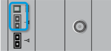
Ensite X Amplifier Front Panel: Describe what the following Ensite X Amplifier Status Indicator lights tell us (AND, if applicable, what we should do):
Steady Orange
Flashing Orange
Steady Orange/Green
Flashing Green
Steady Green
Off
System performing self-testing
Something has failed - restart or call technical service
Restart or call technical service
Check fiber-optic cable between Ensite X Amplifier and DWS; verify Ensite X DWS is powered on
System is ready
System is turned off

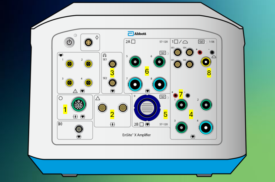
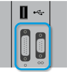
Tell me what connections each of these ports #1-8 support on the front panel of the Ensite X Amplifier.
SurfaceLink Port where the SurfaceLink houses the locating electrodes, 12-lead, RL, and ECG electrodes → enable current to be sent to locating electrodes, and ECG and EGM data to be sent to Ensite X and recording system
PRS ports (interchangeable) for magnetic field
SE ports for SE ablation catheters
Bank 1, green supports </= 10 electrodes, blue supports 11-22 electrodes or 20-pin CIM. Channels 1-56
Bank 2B for 80-pin CIM, only use channels 57-120. Can’t use if Bank 2A is in use
Bank 2A, green supports </= 10 electrodes, blue supports 11-22 electrodes or 20-pin CIM. Channels 57-120. Can't use if Bank 2B is in use
Stimulator connection ports to connect a pacing stimulator
Ampere Connect connection. Connects to back of Ampere Generator. Passes along catheter location and EGM data. Channels 53-56 in Bank 1

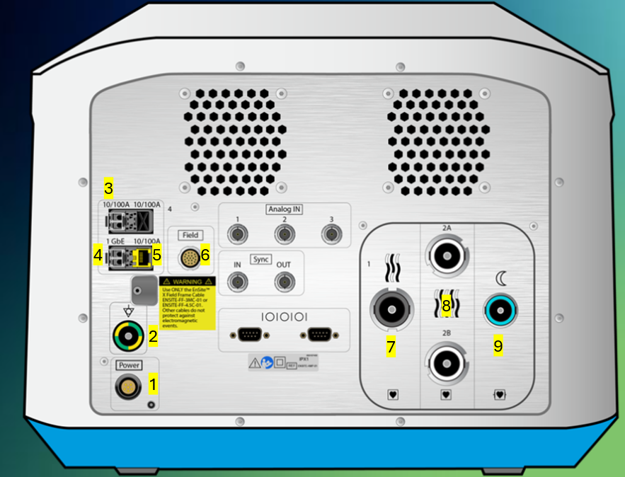
Tell me what connections each of these ports #1-9 support on the back panel of the Ensite X Amplifier.
Power cable
Grounding cable
LC Fiber optic connection for Amplifier to back of Ampere RF Generator as Dual Fiber Optic connection - RF metrics (temp, power, impedance, current, energy) and AutoMarks
LC Fiber optic connection to DWS - all data
Ethernet connection to back of TactiSys - communicates contact force
Field frame connection
EGM output channels 1-56 (or 52 for third party since 53-56 have different pin out), direct connect to Claris or 56 pin-out to 3rd party recording system
EGM output channels 57-120, direct connect to Claris or 64 pin-out to 3rd party recording system
ECG output channels to recording system, direct connect to Claris our 12-lead ECG output module box to 3rd party recording system
Corresponding recording system channel numbers for the following port numbers
Port 1 (green)
Port 2 (green)
Port 3 (green)
Port 4 (blue)
Ampere Connect
Port 5 (green)
Port 6 (green)
Port 7 (blue)
Port 8 (blue)
1: 1-10
2: 11-20
3: 21-30
4: 31-52
AC: 53-56
5: 57-66
6: 67-76
7: 77-98
8: 99-120
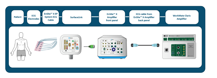
Describe ECG Signal Path with Claris
See picture
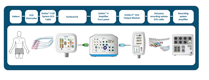
Describe ECG signal path with 3rd party recording system
See picture
If I don’t have what sensors connected to the Ensite X Amplifier, I can still operate in NavX mode but cannot collect SE points for NavX SE field scaling?
The PRS sensors - connect to the front of the Ensite X Amplifier
If SE diagnostic catheters (i.e. HD Grid) don’t get plugged into the SE magnetic ports, how is their SE information connected to Ensite X?
The direct connect cables have a built-in SE connection
What is the magnetic (SE) port for?
For Sensor Enabled Ablation catheters - Tacticath SE, TactiFlex SE, and FlexAbility SE
It communicates magnetic and sensor information to Ensite X, enabling us to collect VoXels from the shaft magnetic sensor
Describe my two options for external stimulator connection ports
One set for ablation catheter, one set for diagnostic catheter
How should I position the field frame cable to connect to…
1) Ensite X back panel
2) Field frame
1) 3 o’clock notch
2) 6 o’clock notch
If I want to connect an Ampere Remote Controller, what cable should I use, where should things connect, and what info does the small fiber optic cable transmit?
Use a double fiber optic cable from the back of Ampere (upper two ports) and connect it to the back of the remote controller
Small fiber optic connection enables the standby button to be turned on/off
Describe what piece of equipment has the following connection ports, and describe what connects/what information is transmitted
This is the back of Ampere RF Generator
Left: connects to the back of CoolPoint to transmit irrigation information for the catheter
Right: connects to Claris or a 3rd party recording system to provide RF metrics to this system
What happens to impedance if I add another grounding pad?
Current flows more easily through the tissue to reach the grounding pads, so lower baseline impedance recorded at tissue surface
Two scenarios that would automatically require the use of two grounding pads
Ablating above 50 W
Using an 8 mm ablation catheter
The TactiSys RF cable (teal to yellow connection, back of TactiSys to the front of the Ampere) enables what 3 things?
Enables power, delivery of RF from ablation catheter
Transmits information about catheter location and EGMs