EP Product Training: Ensite X EP System
1/43
There's no tags or description
Looks like no tags are added yet.
Name | Mastery | Learn | Test | Matching | Spaced |
|---|
No study sessions yet.
44 Terms
What is the benefit of Ensite X EP System in comparison to Ensite Precision System?
Reduction of cabling and simplified connections
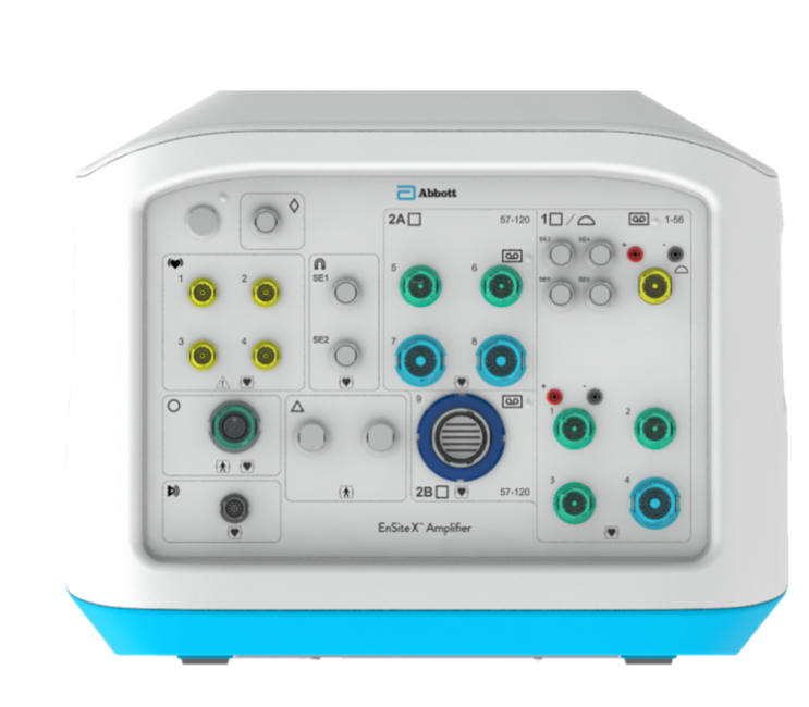
Ensite X Amplifier Front Panel: front panel allows for what type of cable attachment? What was the previous connection type before the front panel was redesigned?
Direct connect cables for nearly all of Abbott’s catheters. Green = direct connect for catheter with </= 10 electrodes, blue = direct connect for catheter with 11-22 electrodes
Previously: Catheters connect to Catheter Input Module (CIM), which, in turn, connected to amplifier

Ensite X Amplifier Front Panel: describe the new signal pathway for EGMs and ECGs
EGM and ECG data pass through Ensite X Amplifier FIRST, then through the recording system (i.e. no split for EGM between Ensite X amplifier and recording system)
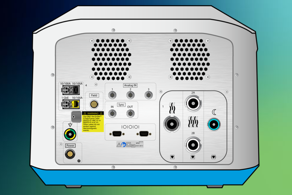
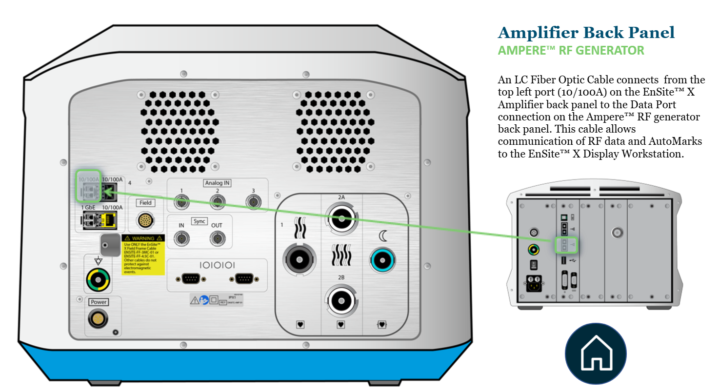
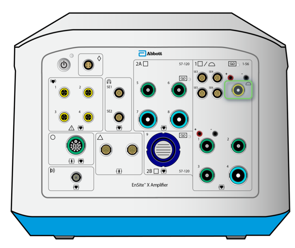
Ensite X Amplifier Back Panel: where does the Ampere RF Generator connect? What does this connection enable?
From top left port (10/100 A) on Ensite X Amplifier → Data port connection on Ampere RF generator back panel
Communicates RF data and AutoMarks to the DWS

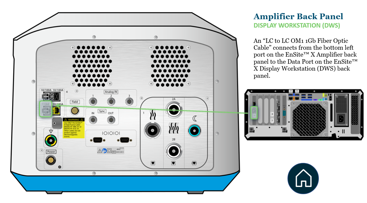
Ensite X Amplifier Back Panel: where does the Ensite X DWS connect?
Fiber optic cable connects from bottom left port (1 GbE) on Ensite X Amplifier → Data port on Ensite X DWS (left) back panel

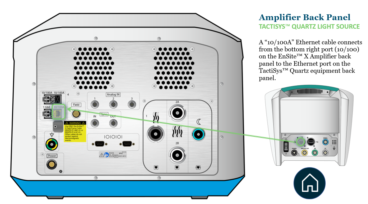
Ensite X Amplifier Back Panel: where does the TactiSys Quartz connect?
Ethernet cable connects from bottom right port (10/100A) on Ensite X Amplifier → Ethernet port on TactiSys Quartz equipment back panel

Ensite X Amplifier Back Panel: where does the Ensite X Field Frame connect?
Field port on Ensite X Amplifier to port on Ensite X Field Frame
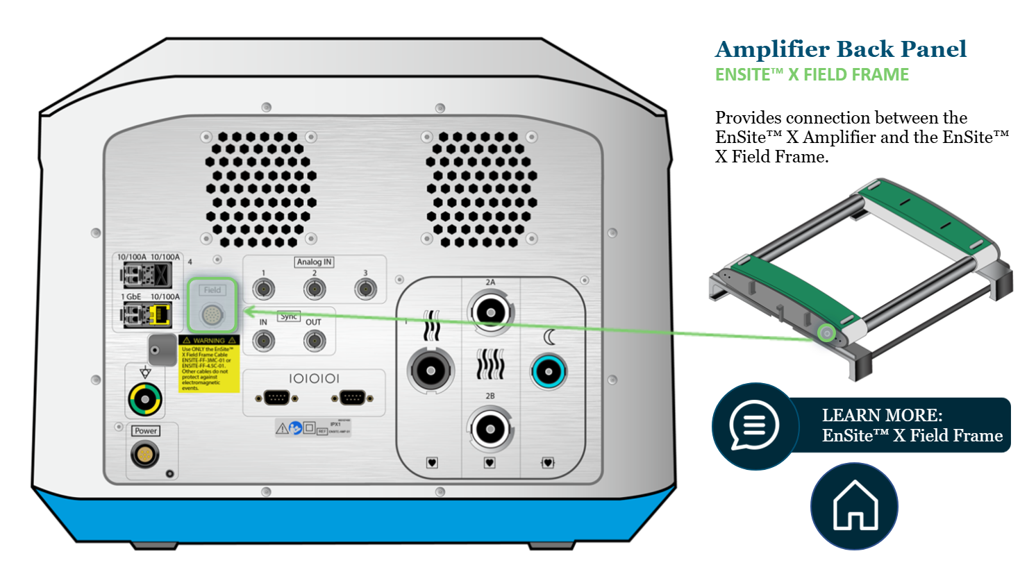
What is the purpose of the Ensite X Field Frame?
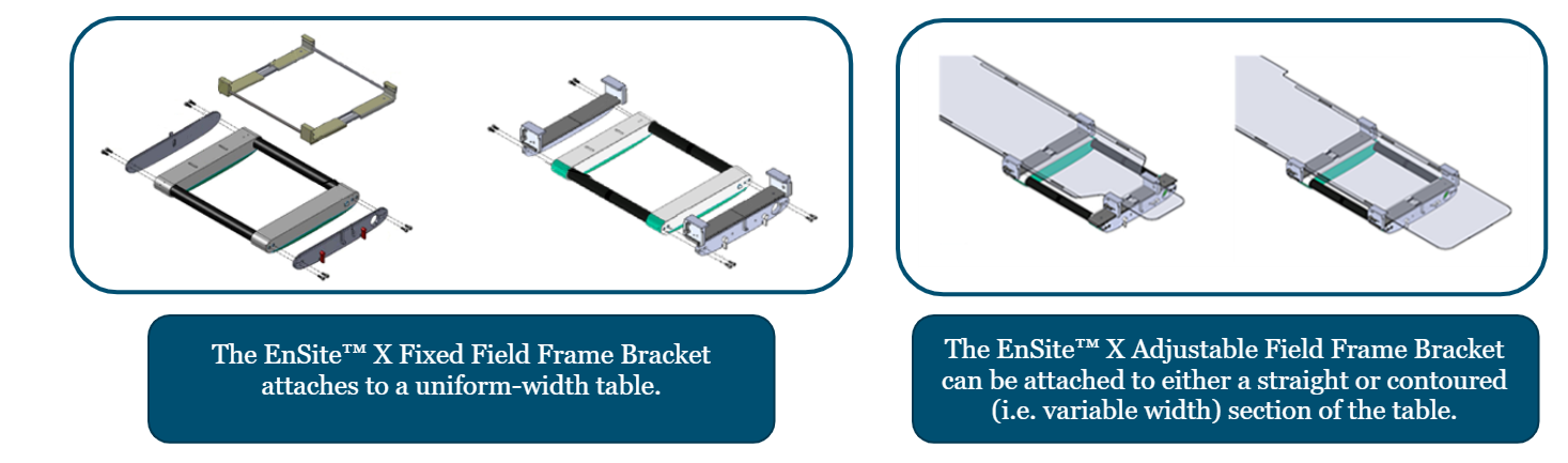
What are the two frame options to attach it to the patient table?
Creates the magnetic tracking field for the Ensite X EP System
Options
Ensite X Fixed Field Frame Bracket: for uniform-width table
Ensite X Adjustable Field Frame Bracket: for uniform OR variable-width table
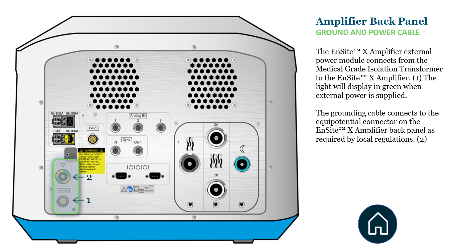
Ensite X Amplifier Back Panel: where do the Ground and Power Cable connect?
Power cable: connects from medical grade isolation transformer to the Ensite X amplifier at the very bottom left port. *Light turns green when on.
Grounding cable: connects at the equipotential connector at bottom left of Ensite X amplifier

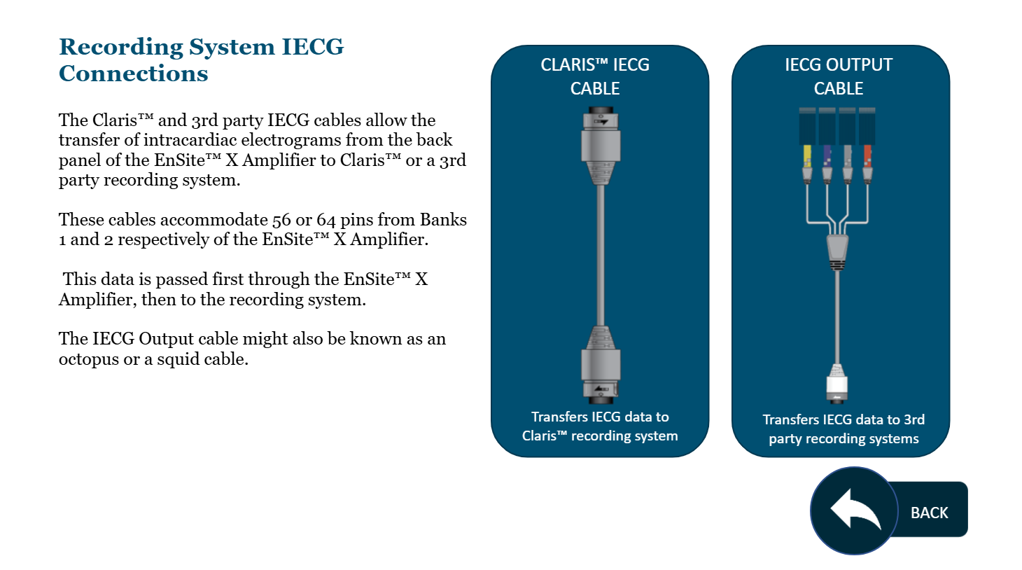
Ensite X Amplifier Back Panel: where do the Recording System IECG cables connect?
Gray 56-pin IECG output cables (think 3rd party recording or Claris) → Bank 1
Pass data from Bank 1 to channels 1 - 56 on the recording system
White 64-pin IECG cables → Bank 2A or 2B
Pass data from Bank 2 to channels 57 - 120 on the recording system
intracardiac electrograms data → Ensite X Amplifier → recording system
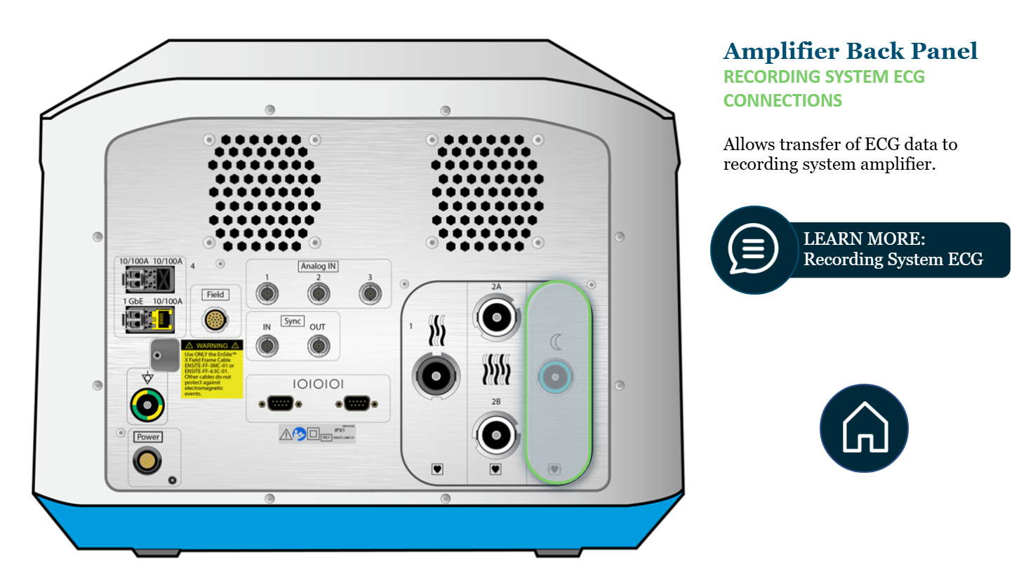
Ensite X Amplifier Back Panel: where do the Recording System ECG cables connect?
Connect to “moon port” (blue) on Ensite X Amplifier
ECG data → Ensite X amplifier → recording system
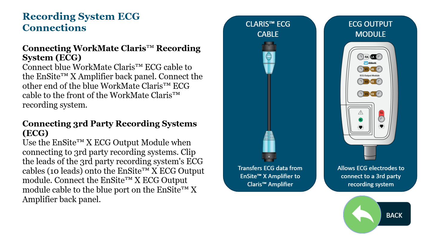
If I want to collect ECG data on my recording system, how do I do this - two options?
Claris: ECG data → Ensite X amplifier → blue WorkMate Claris ECG cable connects Ensite X Amplifier back panel (blue port) to WorkMate Claris front panel
3rd Party Recording: ECg data → Ensite X Amplifier → Ensite X ECG Output module cable connects Ensite X Amplifier back panel (blue port) to leads of the 3rd party recording system

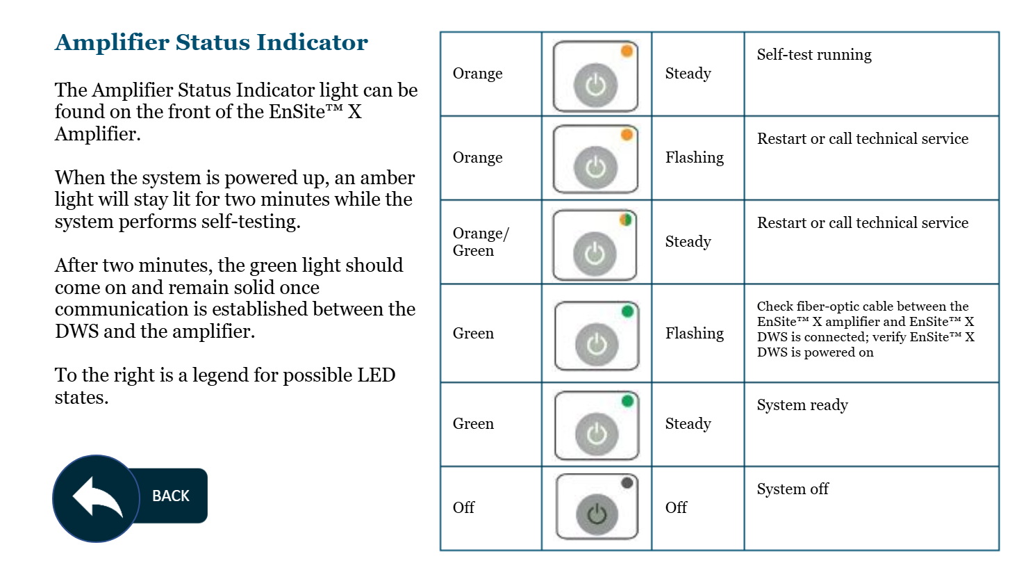
Ensite X Amplifier Front Panel: Describe what the following Ensite X Amplifier Status Indicator lights tell us (AND, if applicable, what we should do):
Steady Orange
Flashing Orange
Steady Orange/Green
Flashing Green
Steady Green
Off
System performing self-testing
Restart or call technical service
Restart or call technical service
Check fiber-optic cable between Ensite X Amplifier and DWS; verify Ensite X DWS is powered on
System is ready
System is turned off
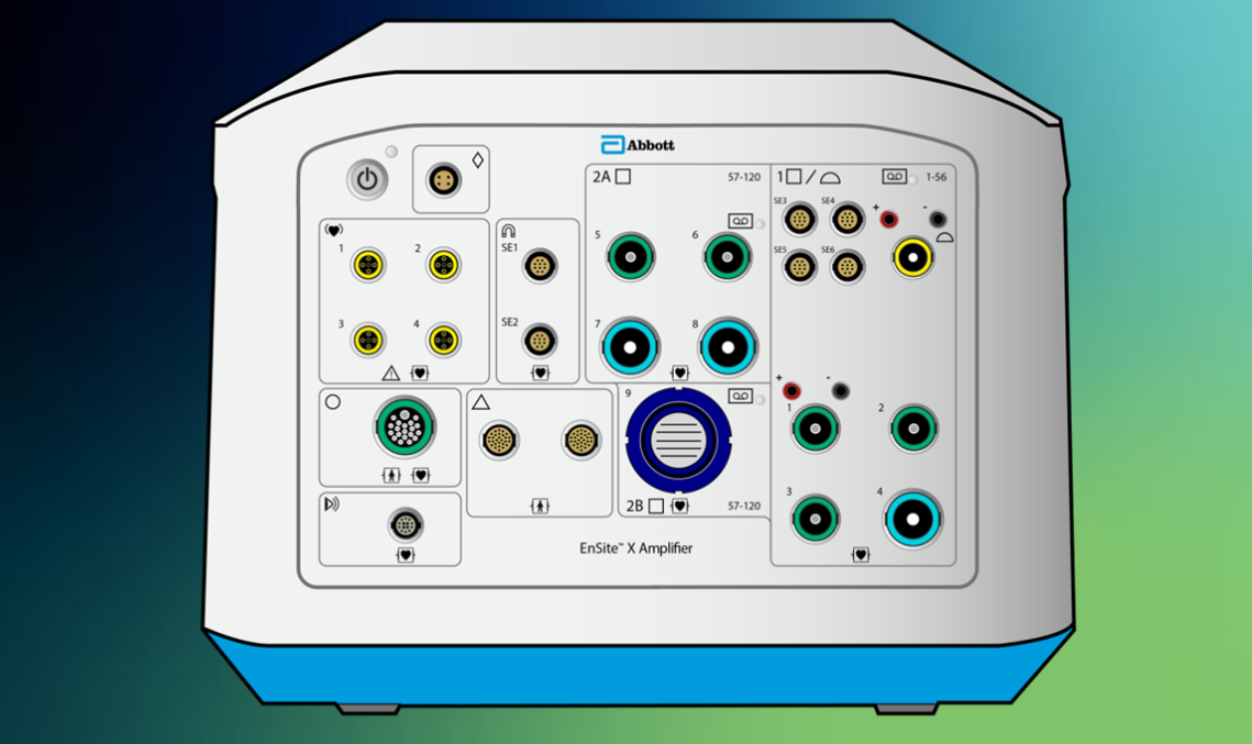
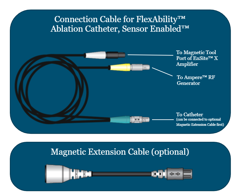
Ensite X Amplifier Front Panel: how do we connect Sensor Enabled Ablation Catheters?
What connection cable is used?
Connect SE catheter to either of the SE magnetic tool ports on the front panel of the Ensite X Amplifier
Use a split connection cable: one end connects to the SE catheter; the other end splits to connect to the Ampere RF Generator and Ensite X Amplifier. Can use a Magnetic Extension Cable between catheter and blue end of connection cable to add length

Ensite X Amplifier Front Panel: how do we connect the 12-lead EKG and Ensite X mapping patches (NOT PRS)?
What intermediate connection is used?
Connect to the surface link port on the front panel of the Ensite X Amplifier
Intermediate connection is the Ensite X SurfaceLink module, whose 8-ft cable plugs into the amplifier

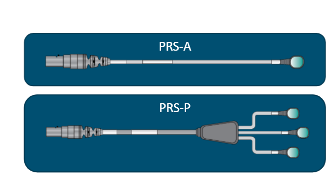
Ensite X Amplifier Front Panel: how do we connect the Patient Reference Sensor cables?
Connect PRS-A and PRS-P cables to either of the PRS ports on the front panel of the Ensite X Amplifier
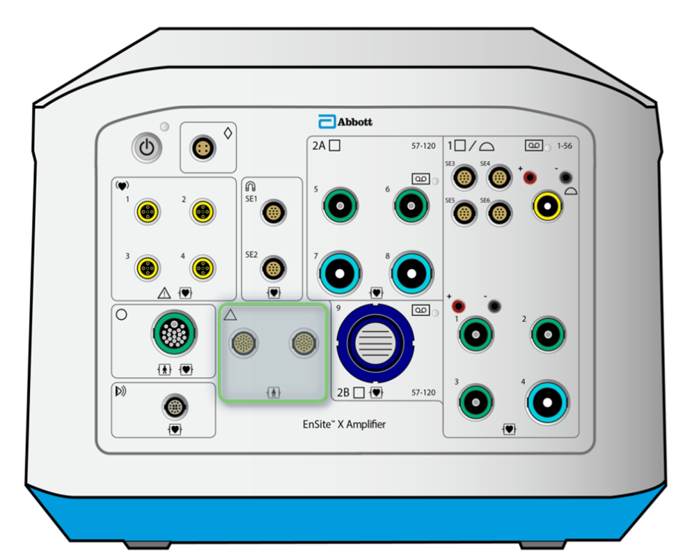
What do these PRS Cables accomplish:
PRS-A
PRS-P (3x)
Detects and compensates for metal distortion. Patch must be flat and oriented 30 degrees to the left
Compensate for patient movement. Center of the PRS-P triangle around the heart is the “zero” of the magnetic coordinate system, i.e. reference point for catheters in the heartS
True or False: The Ensite X EP System is only compatible with the Ampere RF Generator
True

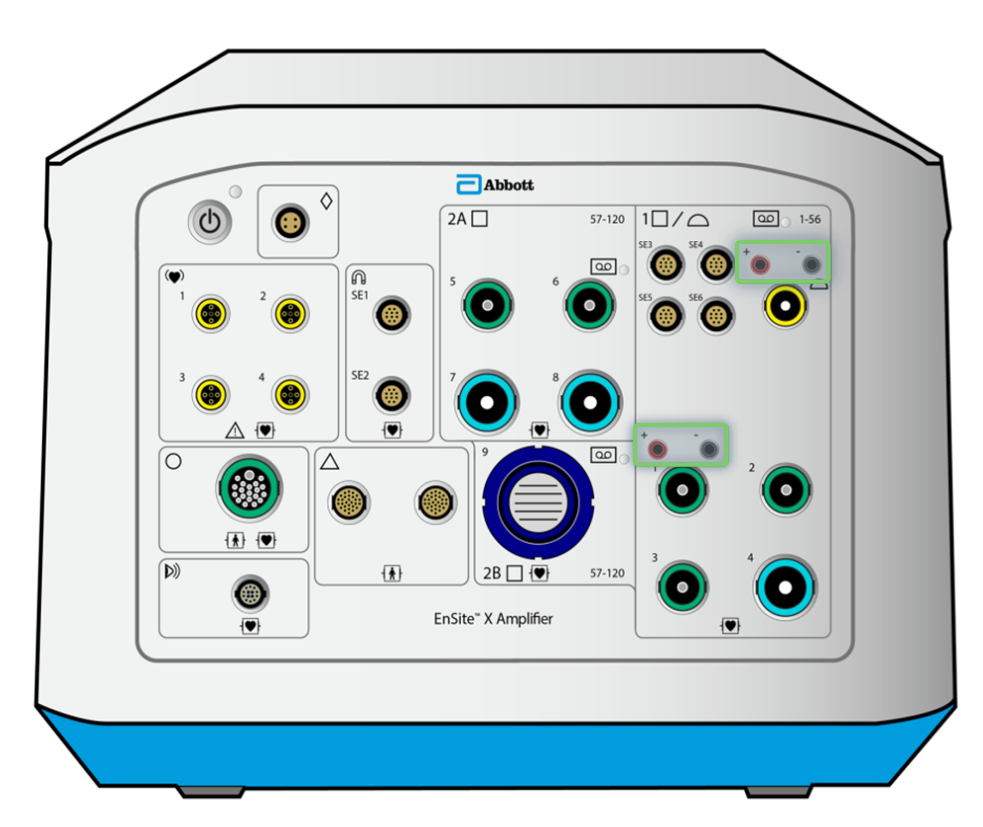
Ensite X Front Panel: How to connect the AmpereConnect cable?
What does this connection enable?
Connects from front panel of the Ampere RF Generator to the front panel of the Ensite X Amplifier
Transmits ablation catheter impedance, location, and signal data to Amplifier
Ensite X Front Panel: How to transmit Ablation catheter EGMS to recording system?
Ablation EGMs are passed from the AmpereConnect port in Bank 1 to pins 53-56 of the recording system

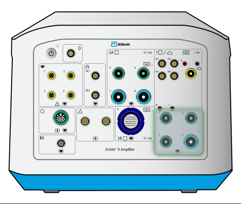
Ensite X Front Panel: How to connect Direct Connect catheters into Bank 1?
Connect catheters with </= 10 electrodes to green catheter ports; connect catheters with 11-22 electrodes to blue catheter ports (IN BANK 1). This connects the catheters to recording amplifier channels 1-56
Into which port of the Ensite X Amplifier would the 20-pin CIM be able to connect?
Into any of the LIGHT BLUE catheter ports on the front panel (if a catheter is not direct connect)

Ensite X Amplifier Front Panel: What do the pacing stimulator connection ports enable?
Direct connection of a pacing stimulator in case of a power failure, either ablation catheter (top) or diagnostic catheter (bottom)

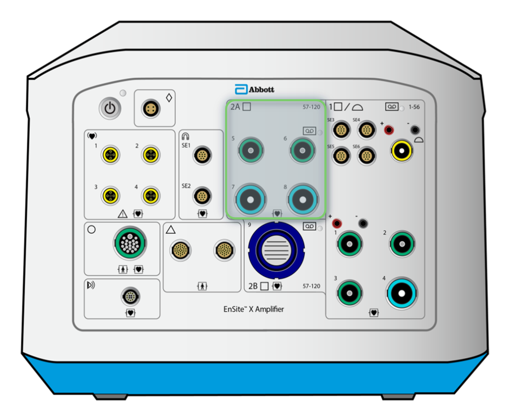
Ensite X Front Panel: How to connect Direct Connect catheters into Bank 2 (A or B)?
Green for catheters with </= 10 electrodes; blue for cathetrs with 11-22 electrodes
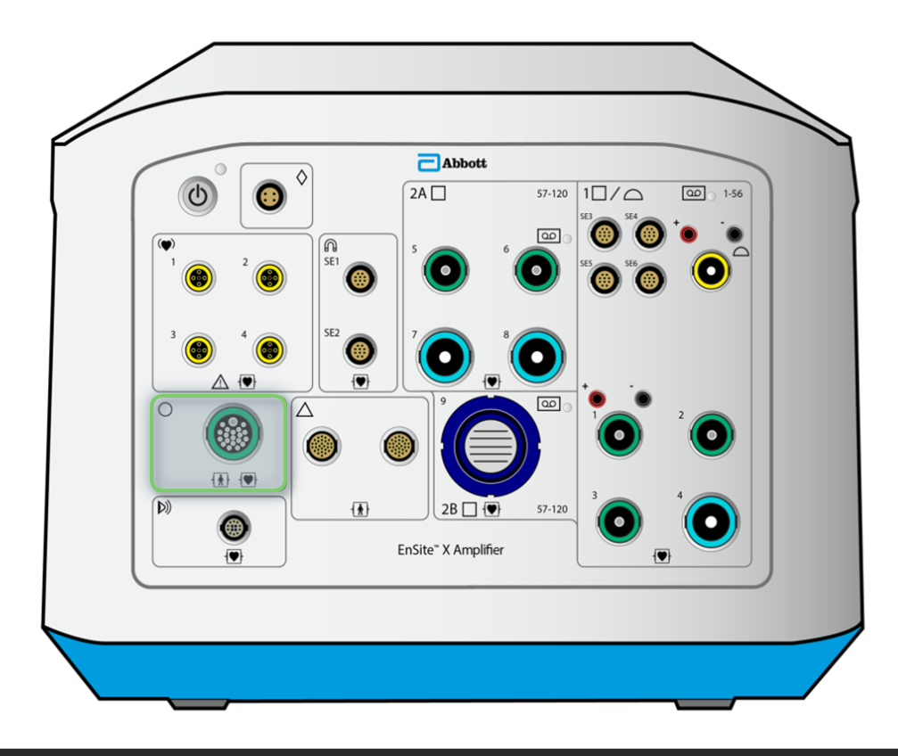
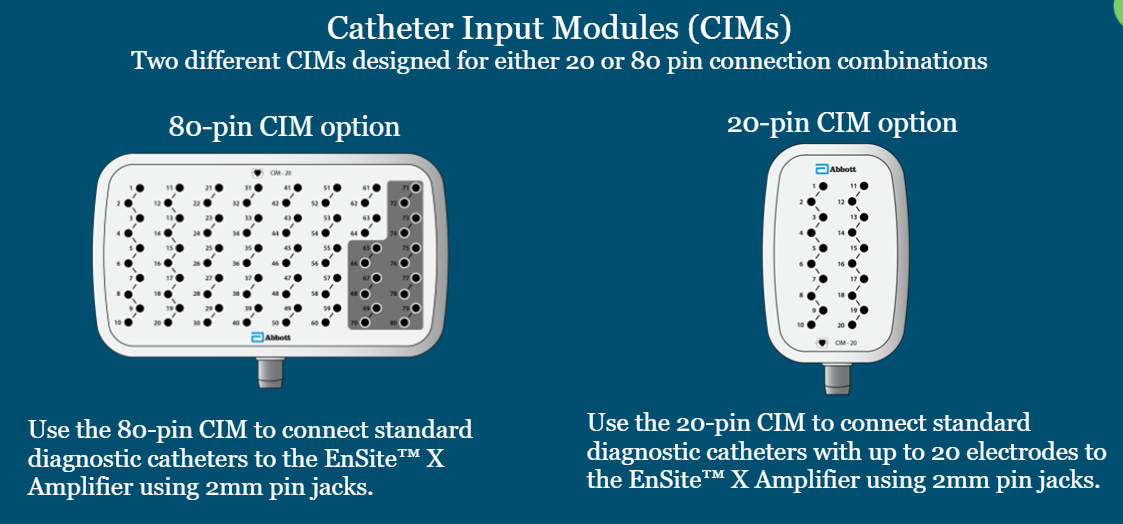
What are our two options for CIMs to connect standard diagnostic catheters to the Ensite X Amplifier?
80-pin CIM
20-pin SIM (cathter with up to 20 electrodes)

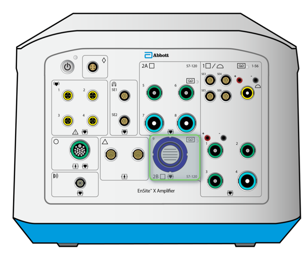
Ensite X Amplifier Front Panel: Identify the High Density Catheter Port. What does it do?
Bank 2B. Connects the 80-pin CIM, which acts as the intermediary between catheters and recording amplifier channels
EnSite X EP Direct Connect Catheter Cable References:
Order of codes
What does this example stand for? Ex: D-ENS-L/R-BQ-CBL
Catheter family codes, what do they stand for: L/R, SUP, INQ
Electrode codes, what do they stand for: D, DD, O, H, B, Q
Product Category - System Code - Catheter Family - Number of Electrodes - Product Type
Diagnostic, Ensite, Livewire/Response, Bipolar/Quadripolar, Catheter Cable
L/R = Livewire/Response, SUP = Supreme, INQ = Inquiry
D = decapolar, DD = duodecapolar, O = octapolar, H = hexapolar, B = bipolar, Q = Quadripolar
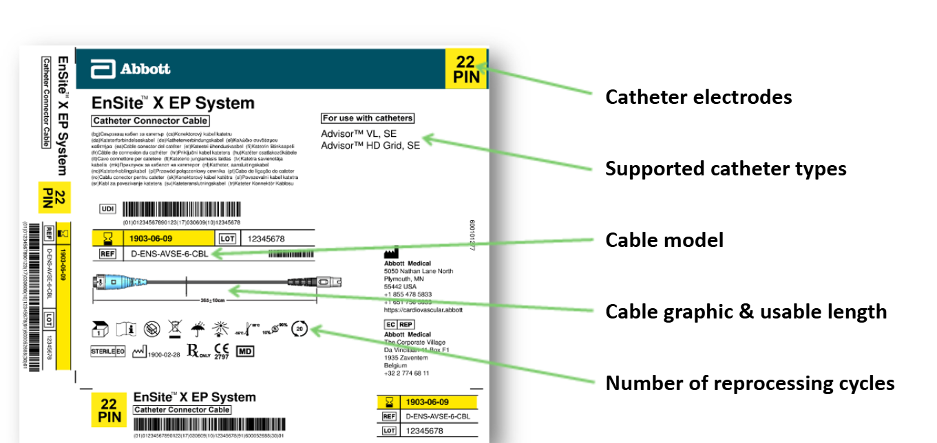
On a catheter connector cable box label reference, where is the:
Number of catheter electrodes
Supported catheter types
Cable model
Cable usable length
Number of re-processing cycles
See picture
True or False: The TactiCath Contact Force Ablation Catheter, Sensor Enabled, has the Direct Connect Cable integrated into the catheter.
True!
In Bank 1 on the front panel of the Ensite X Amplifier, what channels do the following ports support?
Port 1 (green)
Port 2 (green)
Port 3 (green)
Port 4 (blue)
Channels 1-10 (up to 10 electrodes)
Channels 11-20
Channels 21-30
Channels 31-52 (up to 22 electrodes)
Why do we need to use the Ensite X Surface Electrode Kit during a case?
To use NavX or VoXel mode on the mapping system
Technically Ensite NavX Mode operates without the field frame or magnetic field connections but will be restricted to impedance data only
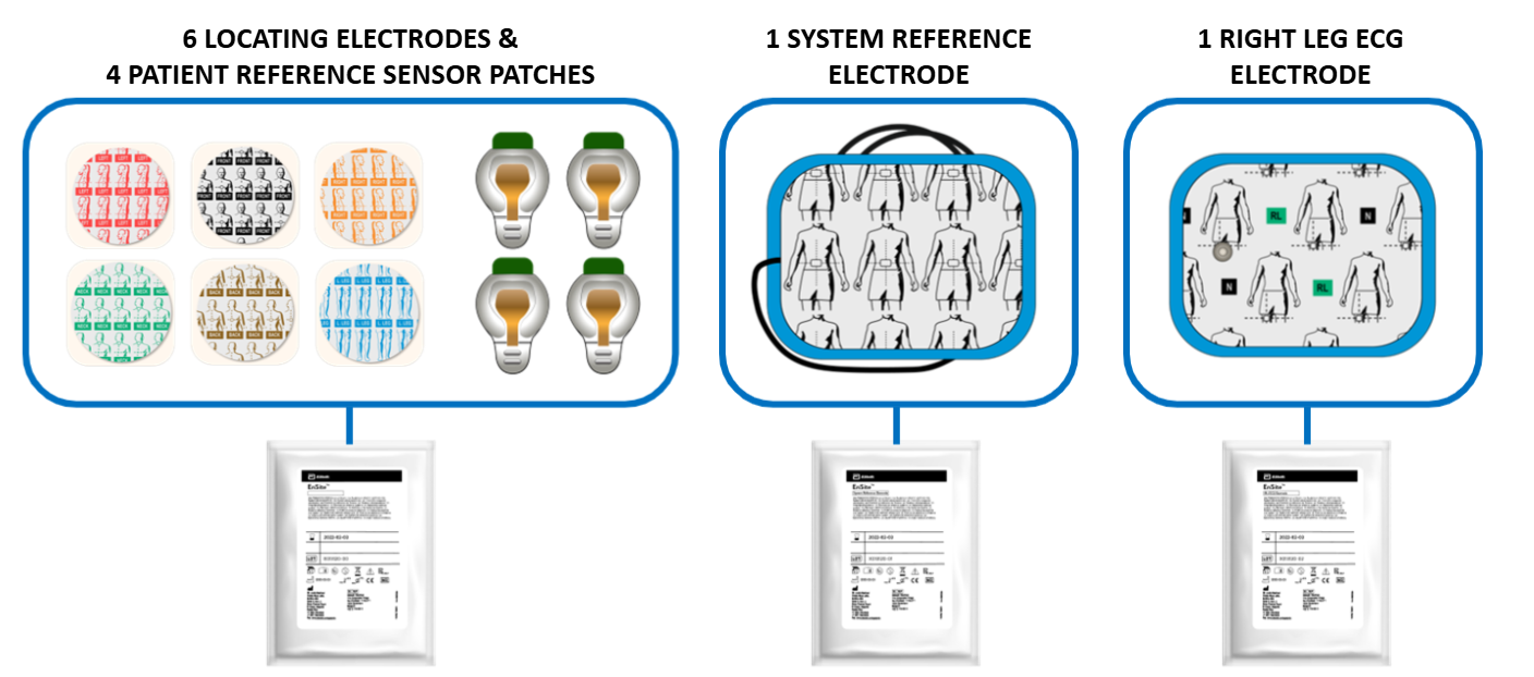
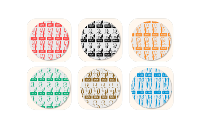
Each Ensite X Surface Electrode Kit contains what patches/sensors?
6 locating electrodes (colored, mapping patches)
4 PRS patches
1 System Reference Electrode
1 Right Leg EKG Electrode
4 steps for skin preparation before placing surface electrodes and patches
Trim excess hair at locations of patch/sensor placement
Gently abrade the skin
Clean the surface of the skin with soap and water
Ensure that the skin is completely dry before placing sensors/patches
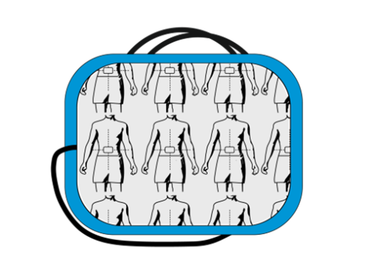
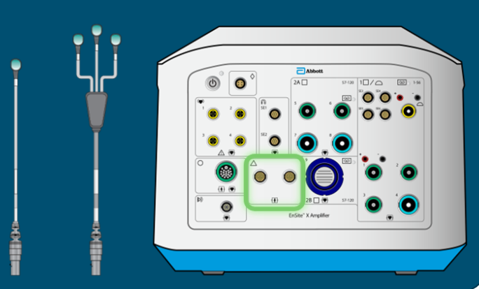
System Reference Electrode:
What does it do?
Where is it placed?
Where is it connected?
System electrical reference for impedance and ECG measurements
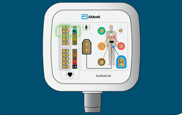
On the patient’s abdomen (think bellybutton) - first one connected, last one disconnected
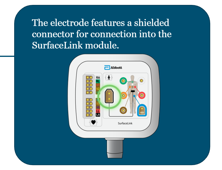
Connects to the shielded connector on the SurfaceLink Module (see picture)
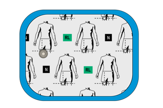
RL ECG Electrode:
What does it do?
Where is it placed?
Where is it connected?
Serves as right leg ECG electrode and cancels out any powerline noise seen by the System Reference
On the patient’s right leg (front)
Connects to the RL ECG port on the SurfaceLink Module (see pic)
Locating Electrodes:
What do they do?
Where are they connected?
Generate the impedance field. Support acquisition of impedance signals to locate the position of electrodes on EP catheters. They send low-intensity currents into the patient’s body to accomplish this.
To the designated ports on the Surface Link module (see pic)
Locating Electrode Placement: front and back
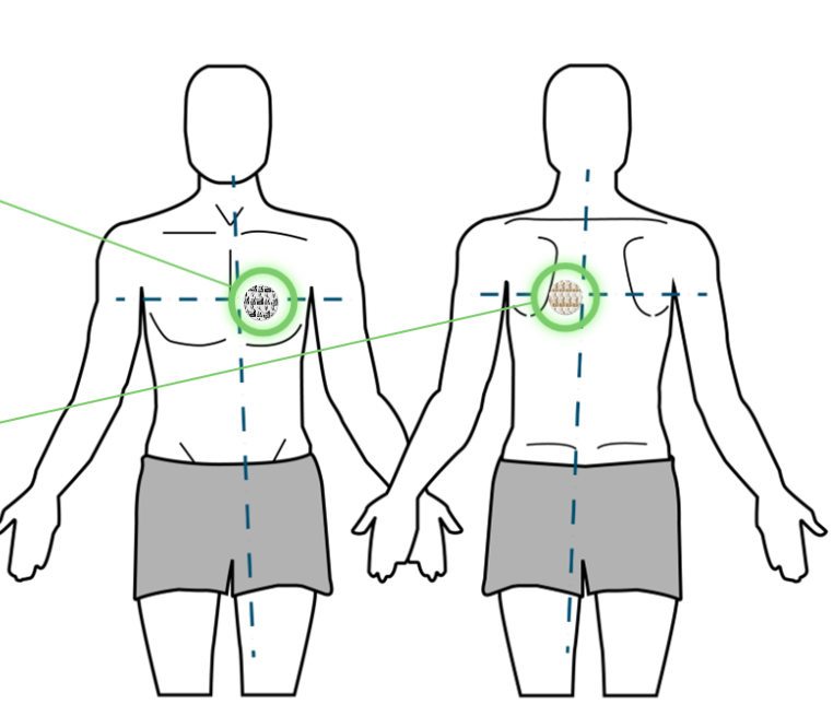
Front: offset slightly to the left of the sternum, next to V2?
Back: Offset slightly to the left of the patient’s spine
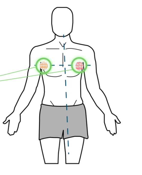
Locating Electrode Placement: right and left
Placed at 180 degrees from each other, in line with the lungs, on patient’s side.
Feed into the RespComp X algorithm
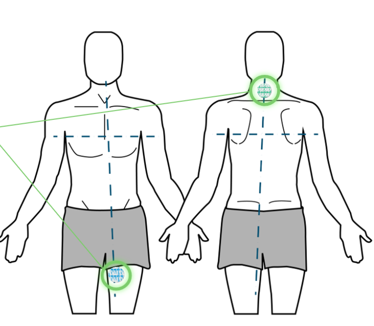
Locating Electrode Placement: neck and leg
Neck: below the crease of the neck, midline
Left Leg: inner thigh
PRS Patches:
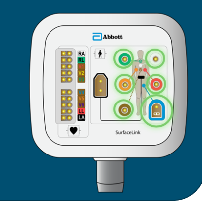
What do they do?
Where are they connected?
Hold PRS sensors; PRS-A to detect metal distortion during a procedure'; PRS-P to form the “zero” of the magnetic coordinate system
The PRS cables attached to the patches plug into either magnetic PRS port on the front panel of the Ensite X Amplifier
Where to place the PRS-A patch?
PRS-A: directly over the heart, 30 angle to the left from midline, routed over left clavicle, no more than 45 degrees relative to the patient table
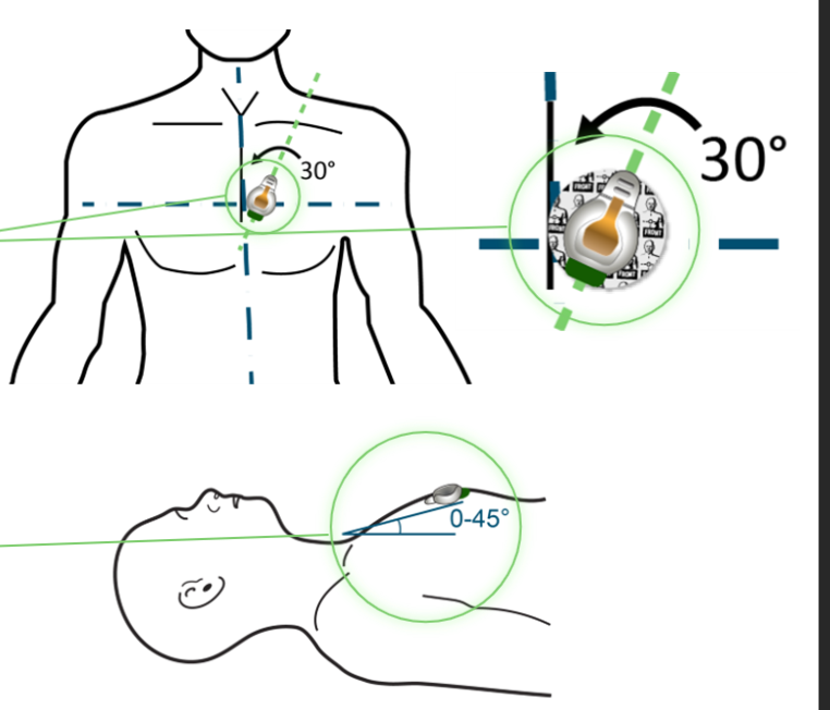
Where to place the PRS-P patches?
PRS-P: In a triangular formation around the heart; 8cm away from each other

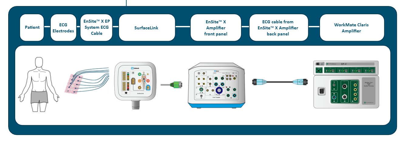
ECG Signal Path from Patient to the Claris Recording System
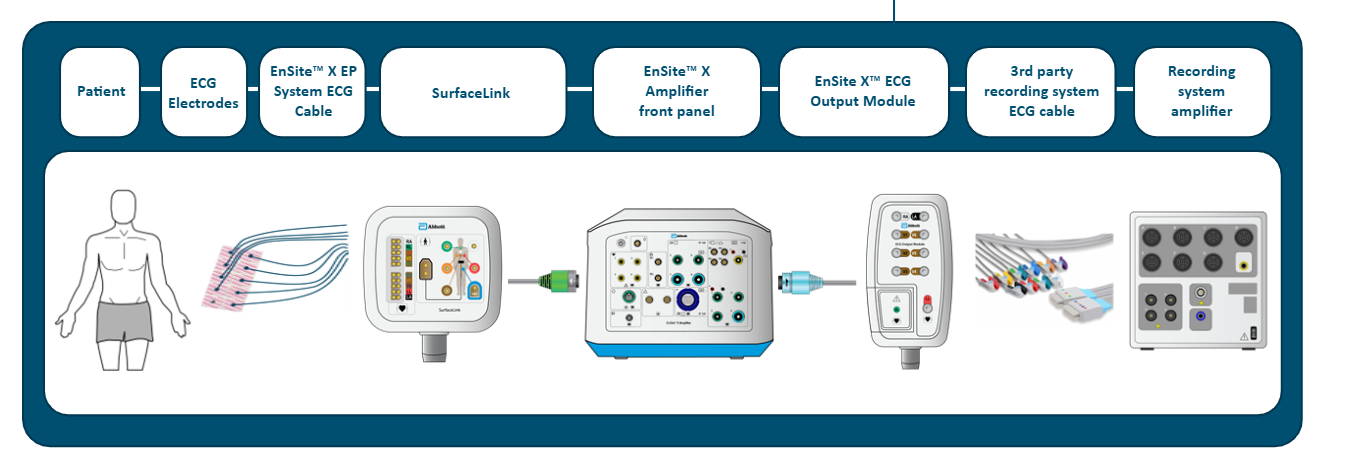
Patient → ECG electrodes → EnSite X EP System ECG Cable → SurfaceLink module → SurfaceLink Port on front panel of Ensite X Amplifier → Light Blue Bank on back panel of Ensite X Amplifier → Claris amplifier
ECG Signal Path from Patient to a 3rd Party Recording System
Patient → ECG electrodes → EnSite X EP System ECG Cable → SurfaceLink module → SurfaceLink Port on front panel of Ensite X Amplifier → Light Blue Bank on back panel of Ensite X Amplifier → Ensite X ECG Output Module → 3rd Party recording system ECG cable → Recording system amplifier