DML Final Exam Review
1/175
There's no tags or description
Looks like no tags are added yet.
Name | Mastery | Learn | Test | Matching | Spaced |
|---|
No study sessions yet.
176 Terms
True or false: for part drawings, the isometric view should not be solid and should not have hidden lines
True
True or false: no hidden lines in orthogonal views
False
how many decimal places should holes be defined?
3
true or false: dimensions should be based on datums and you can have multiple datums
true
true or false: you cannot have multiple of the same views on part drawings
false
should you use multiple pages on part drawings?
if it is needed
what should datums be based on?
how you would take measurements in real life
true or false: avoid dimensioning to tangent lines in part drawings
true
what would be the hole callout for a 1/4-20 threaded hole drilled through aluminum?
0.201 THRU, 1/4-20 UNC THRU
do you use coarse or fine thread for tapping softer materials, i.e, aluminum?
coarse
do you use coarse or fine thread for tapping harder materials, i.e, steel?
fine
Which term best matches the following definition?
"A metal cutting process used for the generation of cylindrical surfaces. Normally the workpiece is rotated on a spindle and the tool is fed into it radially, axially, or both ways simultaneously, to produce the desired surface. The term, in the general sense, refers to the generation of any cylindrical surface with a single point tool."
lathe turning
A variety of work holding methods may be used for machining on a lathe. When a workpiece is [""held between centers"", ""held in a chuck"", ""held in a collet""] , it is clamped in a rotary chuck containing 3 or 4 jaws for security.
held in a chuck
A variety of work holding methods may be used for machining on a lathe. When a workpiece is [""held between centers"", ""held in a collet"", ""held in a chuck""] , it is held in precision cylindrical bushings.
held in a collet
A variety of work holding methods may be used for machining on a lathe. When a workpiece is [""held between centers"", ""held in a collet"", ""held in a chuck""], it is supported between 2 pointed mandrels. This last work holding method is most often used for long, slender workpieces.
held between centers
True or False: All standard tool holders are designed to cut with the cutting edge or point located on the centerline of the machine and workpiece.
true
The red boxed numbers on the included engine lathe illustration refer to specific components of the lathe as indicated by the arrows. Each number is to be matched with the name of its corresponding component. What is number 1?
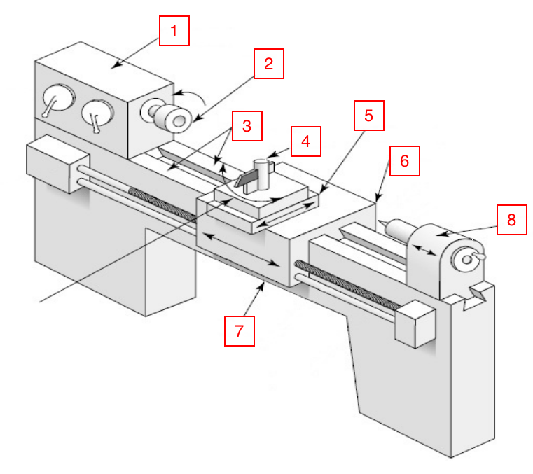
headstock
The red boxed numbers on the included engine lathe illustration refer to specific components of the lathe as indicated by the arrows. Each number is to be matched with the name of its corresponding component. What is number 2?
spindle
The red boxed numbers on the included engine lathe illustration refer to specific components of the lathe as indicated by the arrows. Each number is to be matched with the name of its corresponding component. What is number 3?
ways
The red boxed numbers on the included engine lathe illustration refer to specific components of the lathe as indicated by the arrows. Each number is to be matched with the name of its corresponding component. What is number 4?
tool post
The red boxed numbers on the included engine lathe illustration refer to specific components of the lathe as indicated by the arrows. Each number is to be matched with the name of its corresponding component. What is number 5?
cross slide
The red boxed numbers on the included engine lathe illustration refer to specific components of the lathe as indicated by the arrows. Each number is to be matched with the name of its corresponding component. What is number 6?
carriage
The red boxed numbers on the included engine lathe illustration refer to specific components of the lathe as indicated by the arrows. Each number is to be matched with the name of its corresponding component. What is number 7?
bed
The red boxed numbers on the included engine lathe illustration refer to specific components of the lathe as indicated by the arrows. Each number is to be matched with the name of its corresponding component. What is number 8?
tailstock
Consider the physical and functional differences between an engine lathe and a turret lathe. Match the descriptions with the machine they best match.
This lathe type represents the first step toward high production turning machines.
turret lathe
Consider the physical and functional differences between an engine lathe and a turret lathe. Match the descriptions with the machine they best match.
This lathe type replaces the tailstock and tool post compound assembly with tool-holding turrets.
turret lathe
Consider the physical and functional differences between an engine lathe and a turret lathe. Match the descriptions with the machine they best match.
This machine is better for lower production needs.
engine lathe
Consider the physical and functional differences between an engine lathe and a turret lathe. Match the descriptions with the machine they best match.
This machine includes the "skill of the worker" within itself, so inexperienced operators can reproduce identical parts.
turret lathe
Consider the physical and functional differences between an engine lathe and a turret lathe. Match the descriptions with the machine they best match.
This machine requires a skilled operator and requires more time to produce identical parts.
engine lathe
Consider the physical and functional differences between an engine lathe and a turret lathe. Match the descriptions with the machine they best match.
This machine type is more ideal for higher production needs.
turret lathe
Choose the best definition for the term "milling."
a) A process of generating machined surfaces by progressively removing a predetermined amount of material or stock from the workpiece which is advanced at a relatively high rate of movement or feed to a milling cutter rotating at a comparatively slow speed.
b) A process of generating machined surfaced by progressively removing a predetermined amount of material or stock from the workpiece which is advanced at a relatively slow rate of movement or feed to a milling cutter rotating at a similarly slow speed.
c) A process of generating machined surfaced by progressively removing a predetermined amount of material or stock from the workpiece which is advanced at a relatively slow rate of movement or feed to a milling cutter rotating at a comparatively high speed.
d) A process of generating machined surfaced by progressively removing a predetermined amount of material or stock from the workpiece which is advanced at a relatively high rate of movement or feed to a milling cutter rotating at a similarly high speed.
c
The use of the end and periphery (or side) of the cutting tool to create a shoulder or pocket.
end milling
The use of the end or tip of the cutting tool to create a flat workpiece surface.
face milling
From what material are most solid milling cutters and drills made?
high speed steel (HSS)
What is the most common type of workholding device for a milling machine?
vise
True or False: Drilling accounts for the majority of holes produced in industry today.
true
The red boxed numbers on the included straight shank twist drill illustration refer to specific components of the drill as indicated by the arrows. Each number is to be matched with its corresponding component. What is number 1?
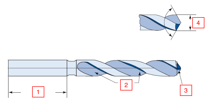
shank length
The red boxed numbers on the included straight shank twist drill illustration refer to specific components of the drill as indicated by the arrows. Each number is to be matched with its corresponding component. What is number 2?
flutes
The red boxed numbers on the included straight shank twist drill illustration refer to specific components of the drill as indicated by the arrows. Each number is to be matched with its corresponding component. What is number 3?
lip
The red boxed numbers on the included straight shank twist drill illustration refer to specific components of the drill as indicated by the arrows. Each number is to be matched with its corresponding component. What is number 4?
drill diameter
The red boxed numbers on the included vertical spindle column and knee mill illustration refer to specific components of the mill as indicated by the arrows. Each number is to be matched with its corresponding component. What is number 1?
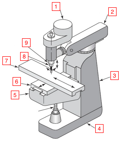
motor
The red boxed numbers on the included vertical spindle column and knee mill illustration refer to specific components of the mill as indicated by the arrows. Each number is to be matched with its corresponding component. What is number 2?
overarm
The red boxed numbers on the included vertical spindle column and knee mill illustration refer to specific components of the mill as indicated by the arrows. Each number is to be matched with its corresponding component. What is number 3?
column
The red boxed numbers on the included vertical spindle column and knee mill illustration refer to specific components of the mill as indicated by the arrows. Each number is to be matched with its corresponding component. What is number 4?
base
The red boxed numbers on the included vertical spindle column and knee mill illustration refer to specific components of the mill as indicated by the arrows. Each number is to be matched with its corresponding component. What is number 5?
knee
The red boxed numbers on the included vertical spindle column and knee mill illustration refer to specific components of the mill as indicated by the arrows. Each number is to be matched with its corresponding component. What is number 6?
saddle
The red boxed numbers on the included vertical spindle column and knee mill illustration refer to specific components of the mill as indicated by the arrows. Each number is to be matched with its corresponding component. What is number 7?
table
The red boxed numbers on the included vertical spindle column and knee mill illustration refer to specific components of the mill as indicated by the arrows. Each number is to be matched with its corresponding component. What is number 8?
spindle
The red boxed numbers on the included vertical spindle column and knee mill illustration refer to specific components of the mill as indicated by the arrows. Each number is to be matched with its corresponding component. What is number 9?
quill
For a "_____" operation, a tool cuts the corner of a cylinder at an angle.
chamfering
A single point tool is fed linearly and parallel to the axis of a workpiece to enlarge a hole made by a previous process in the operation known as "_______."
boring
Surfaces are typically positioned perpendicular to the axis of the workpiece in the "______" operation. This operation is dominated by radial feed.
facing
In an operation known as "________," a regular cross-hatched pattern is produced in work surfaces through metal forming.
knurling
The generation of any cylindrical surface with a single point tool is referred to as "______." In this operation, the direction of the feeding motion is predominantly axial with respect to the machine spindle.
turning
In a "______" operation, both modes of tool feed are simultaneously desired to create tapered and contoured surfaces.
profiling
During a "______" operation, external or internal threads are achieved by feeding a pointed tool linearly across the outside or inside surface of a rotating part.
threading
In the "_______" process, a hole is produced by feeding a drill into a rotating workpiece along its axis.
drilling
For a "______" operation, the end of a part is cut off by feeding a tool radially into a rotating workpiece at a particular location along its length.
parting
true or false:Chips produced during manufacturing are harmless and can be removed with bare hands.
false
what is the five-step check for installing and removing tools on the milling machine.
1. Ensure power is off and the spindle is not rotating
2. Place a table cover below the spindle before changing tools in case something drops
3. Rotate the quill clamp counter-clockwise using your right hand
4. Raise the spindle to the highest position using the quill handle
5. Raise the spindle lock to the highest position by pressing the button, ensuring it’s all the way up by threading it against the top
The maximum depth of cut in the DML lab is ____ thou. A finishing pass is any cut under ___ thou and a roughing pass is anywhere in the range above a finishing pass but below the maximum depth of cut.
100, 20
Which of the following is not part of the 4-step check before turning on the lathe or the mill?
a) Lower the chuck guard/chip shield.
b) Verify that the rotation of the chuck/spindle is spinning in the correct direction.
c) Raise the quill handle to the uppermost position.
d) Ensure that the machine is in the proper speed range.
e) Check that there is clearance around the tool.
c
on the lathe, NEVER leave the ___ key in the ___
chuck, chuck
what is 1 thou?
0.0010 inches
For making a hole in a steel workpiece using a 3/8" drill bit on the mill, what spindle speed should be used?
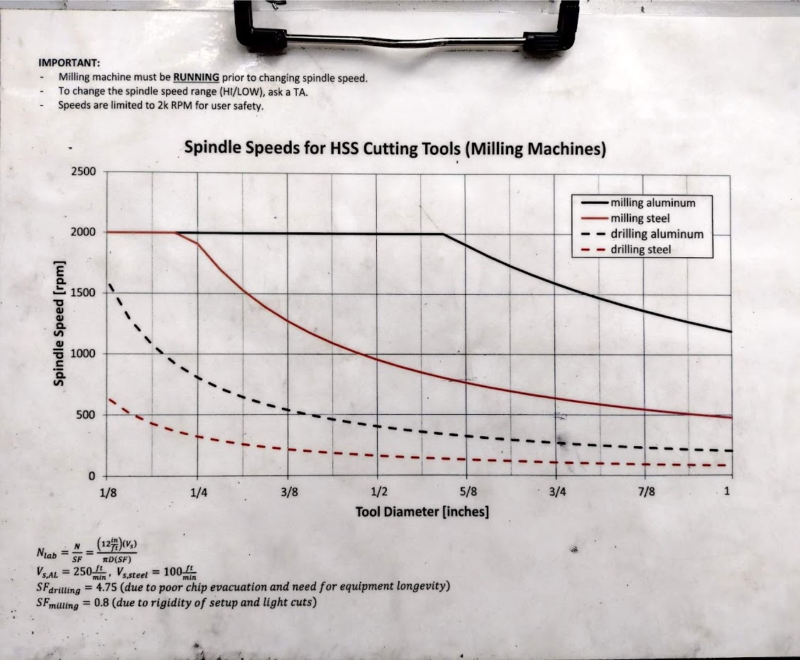
250
On the lathe, the x-axis on the DRO is reading what workpiece measurement?
diameter
When taking a roughing pass on an aluminum workpiece, cutting oil is necessary.
true
true or false: When filing on the lathe, the chuck can still be run at the same RPM that was used for machining.
false
On the milling machine, the speed should NEVER be adjusted when the machine is off.
true
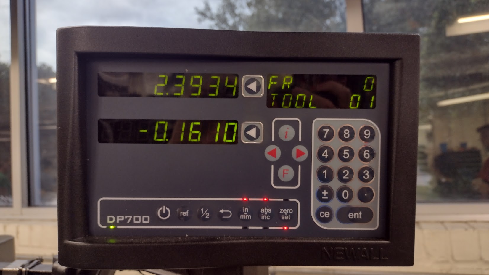
what is the x location on the DRO?
2393 thou
what is the functional difference between a bolt and a screw?
a bolt always requires a nut and a screw does not
The red boxed letters on the fastener illustration refer to specific components of the fastener as indicated by the arrows. Each letter is to be matched with the name of its corresponding fastener feature. What is A?
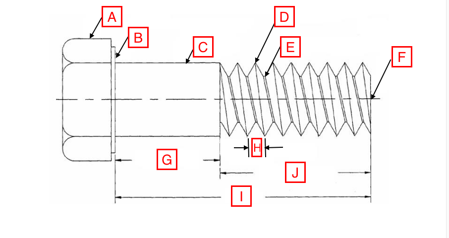
head
The red boxed letters on the fastener illustration refer to specific components of the fastener as indicated by the arrows. Each letter is to be matched with the name of its corresponding fastener feature. What is B?
bearing surface
The red boxed letters on the fastener illustration refer to specific components of the fastener as indicated by the arrows. Each letter is to be matched with the name of its corresponding fastener feature. What is C?
shank
The red boxed letters on the fastener illustration refer to specific components of the fastener as indicated by the arrows. Each letter is to be matched with the name of its corresponding fastener feature. What is D?
thread crust
The red boxed letters on the fastener illustration refer to specific components of the fastener as indicated by the arrows. Each letter is to be matched with the name of its corresponding fastener feature. What is E?
thread root
The red boxed letters on the fastener illustration refer to specific components of the fastener as indicated by the arrows. Each letter is to be matched with the name of its corresponding fastener feature. What is F?
point
The red boxed letters on the fastener illustration refer to specific components of the fastener as indicated by the arrows. Each letter is to be matched with the name of its corresponding fastener feature. What is G?
grip length
The red boxed letters on the fastener illustration refer to specific components of the fastener as indicated by the arrows. Each letter is to be matched with the name of its corresponding fastener feature. What is H?
pitch
The red boxed letters on the fastener illustration refer to specific components of the fastener as indicated by the arrows. Each letter is to be matched with the name of its corresponding fastener feature. What is I?
length
regardless of the country of origin, the two available varieties of fasteners are ____ and ____
coarse and fine
the threads on all quality fasteners are made by being
rolled
why are quality fasteners made through rolling? hint: die or lathe cut threads create stress risers resulting in weak threads that fail prematurely
increased strength, increased fatigue resistance, and reduced cost
the sole purpose of a fastener is to ____
clamp parts together
fastener threads should never be placed in _____
shear
how should engineers prevent relative sliding of parts fastened to each other?
both pins, dowel, and location shoulders
what keeps a fastener tight or secure?
adequate torque, adequate tensile stress
For each case (i.e. coarse and fine thread) dimension the major and minor thread diameters and pitch for the male threads with the correct values off the tap and drill chart. What is A?
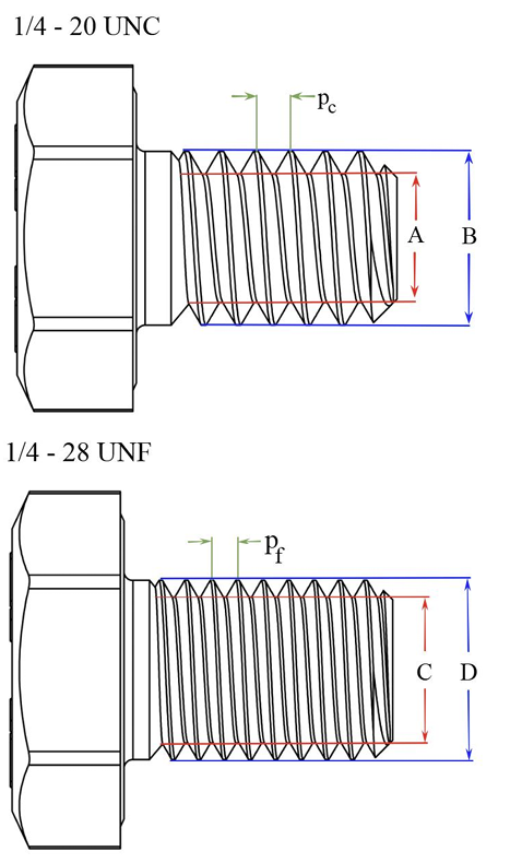
0.189
For each case (i.e. coarse and fine thread) dimension the major and minor thread diameters and pitch for the male threads with the correct values off the tap and drill chart. What is B?
0.250
For each case (i.e. coarse and fine thread) dimension the major and minor thread diameters and pitch for the male threads with the correct values off the tap and drill chart. What is pc?
0.05
For each case (i.e. coarse and fine thread) dimension the major and minor thread diameters and pitch for the male threads with the correct values off the tap and drill chart. What is C?
0.206
For each case (i.e. coarse and fine thread) dimension the major and minor thread diameters and pitch for the male threads with the correct values off the tap and drill chart. What is D?
0.250
For each case (i.e. coarse and fine thread) dimension the major and minor thread diameters and pitch for the male threads with the correct values off the tap and drill chart. What is pf?
0.0357
how many threads of engagement are required for a fastener joint to be considered full strength?
5
what is the minimum number of threads required to torque to 90%?
5
what is the minimum number of threads required to torque to 99%?
7
How do the fastener grade and TPI affect the required preload?
As the fastener grade and TPI increase, so does the desired preload
Which is the equation used to calculate the required fastener torque as a function of the desired preload (Fi) and bolt size (d)?
F=0.2*Fi*d
What does the shank diameter of a 5/16-18 fastener used in an aluminum workpiece measure?
0.313
The total and radial clearances for a close fit hole for a 1/4″ bolt are given as an example.
Total (1/4” close fit): | 0.007" |
Radial (1/4” close fit): | 0.0035" |
How much total and radial clearance does a free fit hole for a 3/8″ bolt leave?
Total (5/16″ free fit): | |
Radial (5/16″ free fit): |
0.022, 0.011