CCNA Chapter 18: Troubleshooting IPv4 Routing
1/39
There's no tags or description
Looks like no tags are added yet.
Name | Mastery | Learn | Test | Matching | Spaced |
|---|
No study sessions yet.
40 Terms
Ping Command Basics
-The ping command tests connectivity by sending packets to an IP address, expecting the device at that address to send packets back
-The command sends packets that mean "if you receive this packet, and it is addressed to you, send a reply back."
-Each time the ping command sends one of these packets and receives the message sent back by the other host, the ping command knows a packet made it from the source host to the destination and back
-More formally, the ping command uses the Internet Control Message Protocol (ICMP), specifically the ICMP echo request and ICMP echo reply messages
-As a protocol, ICMP does not rely on TCP or UDP, and it does not use any application layer protocol. It functions as part of Layer 3, as a control protocol to assist IP by helping manage the IP network functions
Concept Behind ping 172.16.2.101 on Host A
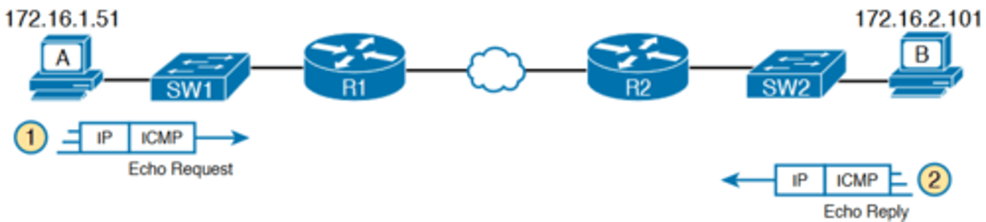
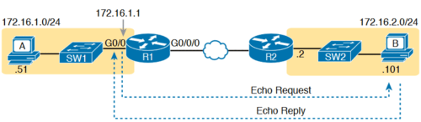
-Figure 18-1 shows the ICMP messages, with IP headers, in an example
-In this case, the user at host A opens a command prompt and issues the ping 172.16.2.101 command, testing connectivity to host B. The command sends one echo request and waits (Step 1); host B receives the messages and sends back an echo reply (Step 2)
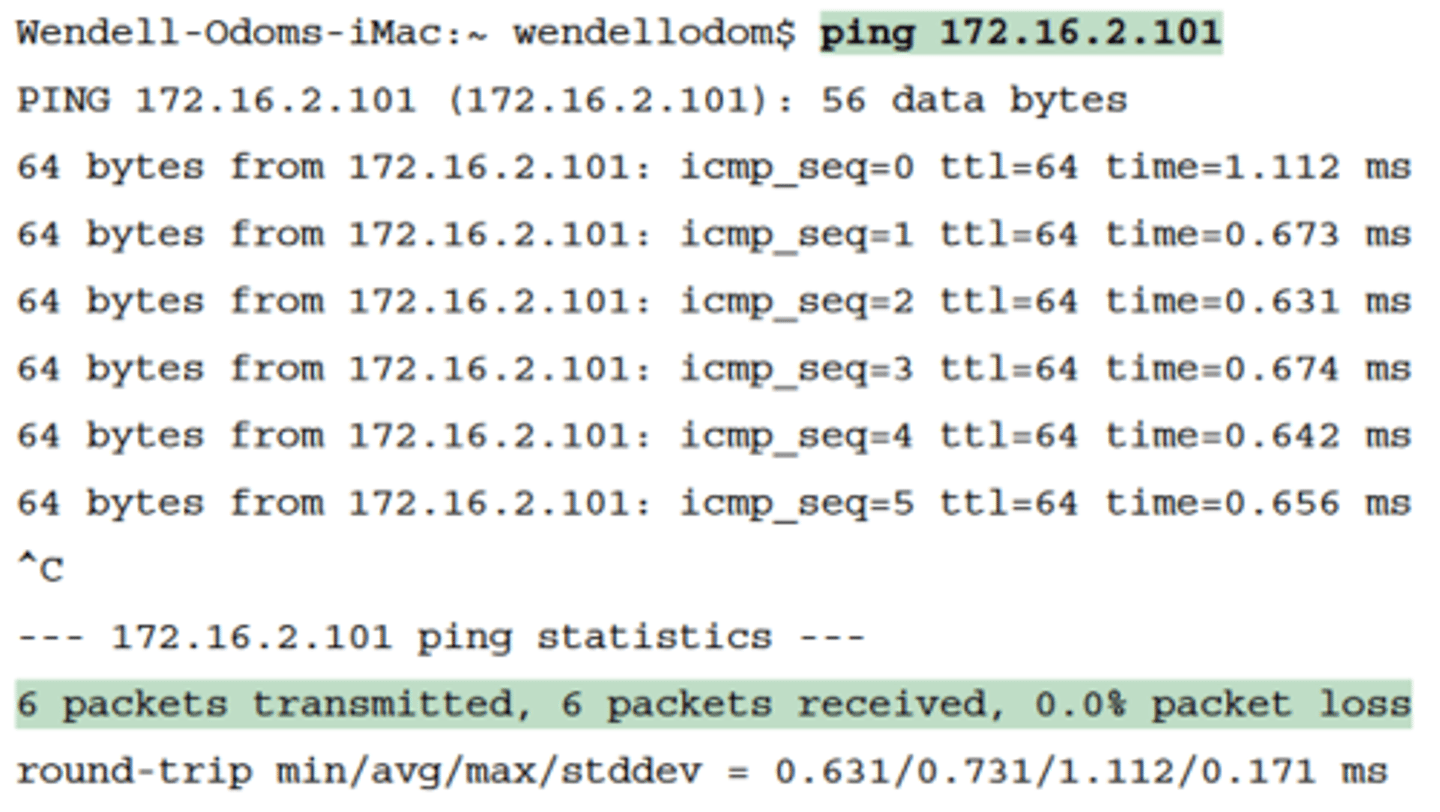
Sample Output from Host A's ping 172.16.2.101 Command
-The ping command is supported on many different devices and many common operating systems.
-The command has many options: the name or IP address of the destination, how many times the command should send an echo request, how long the command should wait (timeout) for an echo reply, how big to make the packets, and many other options
Strategies and Results When Testing with the ping Command
-using different ping commands from different routers can help isolate the problem
-The problem with using ping commands from routers, instead of from the host that has the problem, is that no single router ping command can exactly replicate a ping command done
from the user's device
Testing Longer Routes from Near the Source of the Problem
-Most problems begin with some idea like "host X cannot communicate with host Y."
-A great first troubleshooting step is to issue a ping command from X for host Y's IP address.
-However, assuming the engineer does not have access to host X, the engineer can instead issue the ping from the router nearest X, typically the router acting as host X's default
gateway
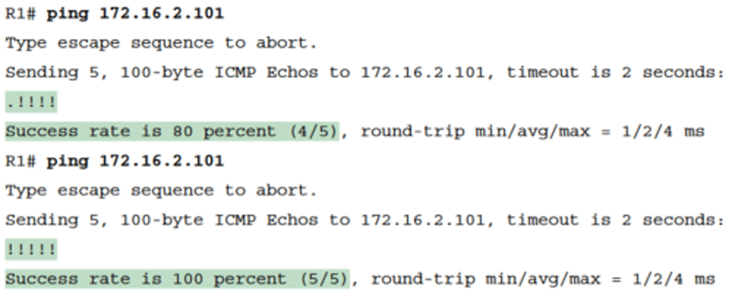
Router R2 Pings Host B (Two Commands)
-For instance, in Figure 18-1, imagine that the user of host A had called IT support with a problem related to sending packets to host B
-A ping 172.16.2.101 command on host A would be a great first troubleshooting step, but the CSR cannot access host A or get in touch with the user of host A.
-So, the CSR telnets to Router R1 and pings host B from there, as shown in Example 18-2
-By default, the Cisco IOS ping command sends five echo messages, with a timeout of 2 seconds
-If the command does not receive an echo reply within 2 seconds, the command considers that message to be a failure, and the command lists a period
-If a successful reply is received within 2 seconds, the command displays an exclamation point
-the first ping command shows one failure to start, but then the rest of the messages work. This usually happens because some device in the end-to-end route is missing an ARP table entry
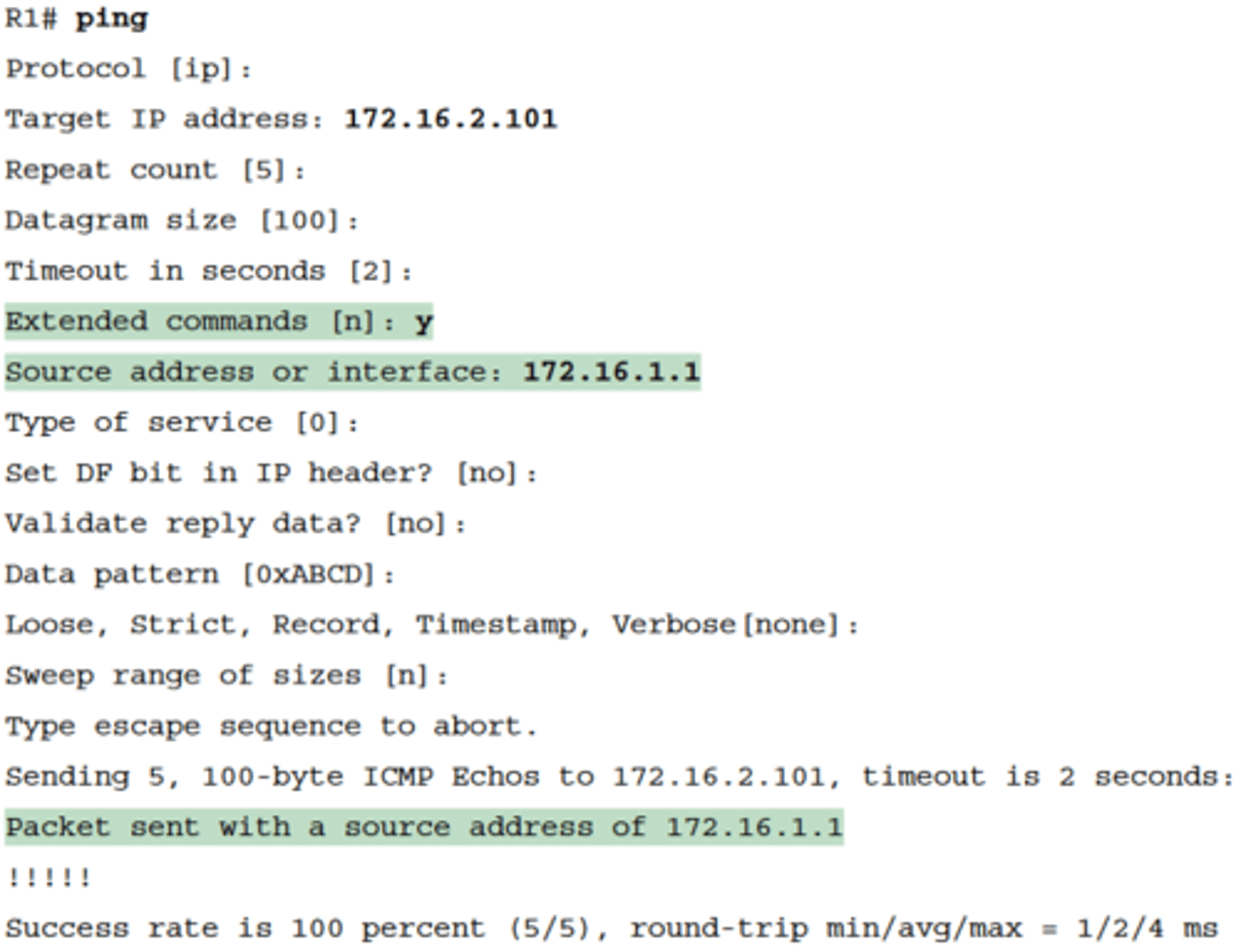
Standard ping 172.6.2.101 Command Using the Source Interface IP Address
■ R1 can send ICMP echo request messages to host B (172.16.2.101).
■ R1 sends these messages from its outgoing interface's IP address (by default), 172.16.4.1 in this case.
■ Host B can send ICMP echo reply messages to R1's 172.16.4.1 IP address (hosts send echo reply messages to the IP address from which the echo request was received).
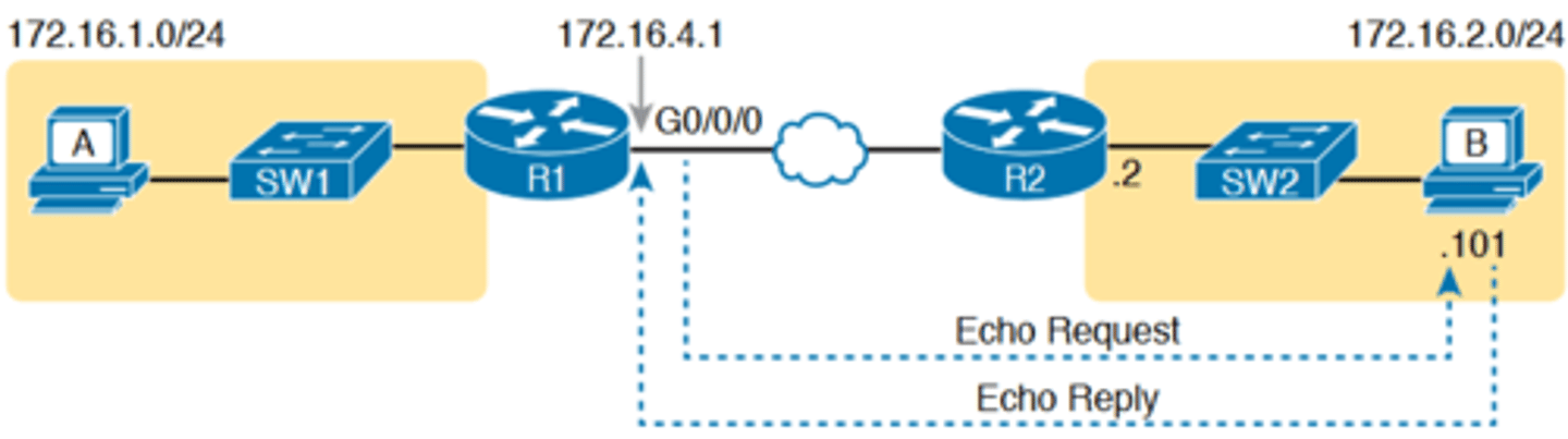
Layer 3 Routes Needed for R1's Ping 172.16.2.101 to Work
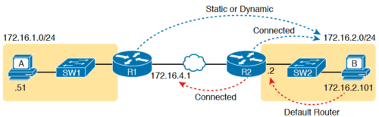
-Next, think about IPv4 routing. In the forward direction, R1 must have a route that matches host B's address (172.16.2.101)
-this route will be either a static route or one learned with a
routing protocol
-R2 also needs a route for host B's address, in this case a connected route to B's subnet (172.16.2.0/24), as shown in the top arrow lines in Figure 18-3
-The arrow lines on the bottom of Figure 18-3 show the routes needed to forward the ICMP echo reply message back to Router R1's 172.16.4.1 interface
-First, host B must have a valid default router setting because 172.16.4.1 sits in a different subnet than host B
-R2 must also have a route that matches destination 172.16.4.1 (in this case, likely to be a connected route).
Layer 3 Routes Needed for R1's Ping 172.16.2.101 to Work cont.
-The working ping commands in Example 18-2 also require the data-link and physical layer details to be working
-The WAN link must be working: The router interfaces must be up/up, which typically indicates that the link can pass data
-On the LAN, R2's LAN interface must be in an up/up state
■ The switch interfaces in use are in a connected (up/up) state.
■ Port security (discussed in the CCNA 200-301 Official Cert Guide, Volume 2) does not filter frames sent by R2 or host B.
■ STP has placed the right ports into a forwarding state
Locations Where IP ACLs Could Have Filtered the Ping Messages
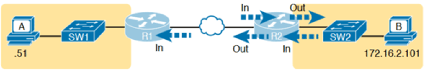
-The ping 172.16.2.101 command in Example 18-2 also confirms that IP access control lists (ACL) did not filter the ICMP messages
-One ACL contains a set of matching rules and actions: some matched packets are filtered (discarded), while others can continue on their path as normal
-ACLs can examine packets as they enter or exit a router interface, so Figure 18-4 shows the various locations on routers R1 and R2 where an ACL could have filtered (discarded) the ICMP messages
Router and Host ARP Tables, with the Switch MAC Address Table
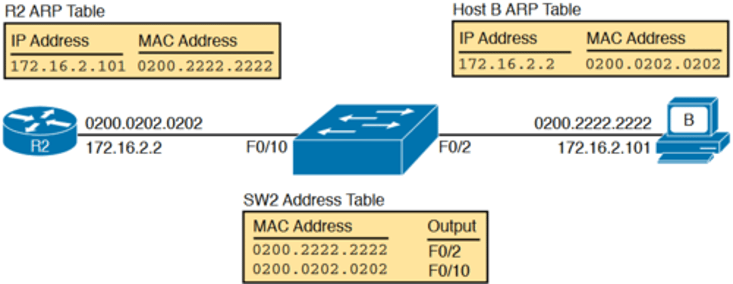
-Finally, the working ping 172.16.2.101 command on R1 can also be used to reasonably predict that ARP worked and that switch SW2 learned MAC addresses for its MAC address table
-R2 and host B need to know each other's MAC addresses so that they can encapsulate the IP packet inside an Ethernet frame, which means both must have a matching ARP table
entry
-The switch learns the MAC address used by R2 and by host B when it sends the ARP messages or when it sends the frames that hold the IP packets
Using Extended Ping to Test the Reverse Route
-Pinging from the default router, as discussed in the past few pages, misses an opportunity to test IP routes more fully. In particular, it does not test the reverse route back toward the
original host
-A standard ping often does not test the reverse route that you need to test.
-In this case, the standard ping 172.16.2.101 command on R1 does not test whether the routers can route back to subnet 172.16.1.0/24, instead testing their routes for subnet 172.16.4.0
-A better ping test would test the route back to host A's subnet; an extended ping from R1 can cause that test to happen.
Extended Ping Command Tests the Route to 172.16.1.51 (Host A)
-Extended ping allows R1's ping command to use R1's LAN IP address from within subnet 172.16.1.0/24. Then, the echo reply messages would flow to host A's subnet, as shown in Figure 18-6
Testing the Reverse Route Using the Extended Ping
-The extended ping command does allow the user to type all the parameters on a potentially long command, but it also allows users to simply issue the ping command, press Enter,
with IOS then asking the user to answer questions to complete the command, as shown in Example 18-3
-The example shows the ping command on R1 that matches the logic in Figure 18-6. This same command could have been issued from the command line as ping 172.16.2.101 source 172.16.1.1
-This particular extended ping command tests the same routes for the echo request going to the right, but it forces a better test of routes pointing back to the left for the ICMP echo
reply
ping command from host
-From a troubleshooting perspective, using both standard and extended ping commands can be useful. However, neither can exactly mimic a ping command created on the host itself
because the routers cannot send packets with the host's IP address
-For instance, the extended ping in Example 18-3 uses source IP address 172.16.1.1, which is not host A's IP address
-As a result, neither the standard or extended ping commands in these two examples so far in this chapter can test for some kinds of problems, such as the following:
■ IP ACLs that discard packets based on host A's IP address but allow packets that match the router's IP address
■ LAN switch port security that filters A's frames (based on A's MAC address)
■ IP routes on routers that happen to match host A's 172.16.1.51 address, with different routes that match R1's 172.16.1.1 address
■ Problems with host A's default router setting
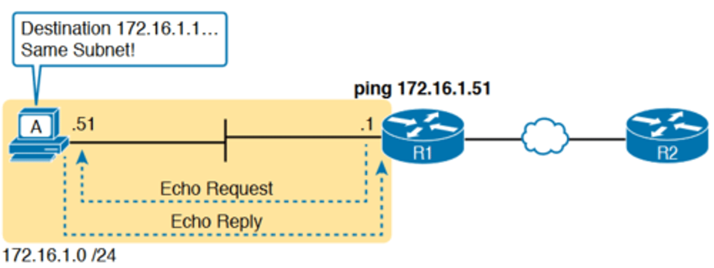
Testing LAN Neighbors with Standard Ping
-Testing using a ping of another device on the LAN can quickly confirm whether the LAN can pass packets and frames.
-If the ping works, it confirms the following, which rules out some potential issues:
■ The host with address 172.16.1.51 replied.
■ The LAN can pass unicast frames from R1 to host 172.16.1.51 and vice versa.
■ You can reasonably assume that the switches learned the MAC addresses of the router and the host, adding those to the MAC address tables.
■ Host A and Router R1 completed the ARP process and list each other in their respective Address Resolution Protocol (ARP) tables.
The failure of a ping
-if the ping 172.16.1.51 on R1 fails (Figure 18-7), that result points to this list of potential root causes:
■ IP addressing problem: Host A could be statically configured with the wrong IP address.
■ DHCP problems: If you are using Dynamic Host Configuration Protocol (DHCP), many problems could exist.
■ VLAN trunking problems: The router could be configured for 802.1Q trunking, when the switch is not (or vice versa).
■ LAN problems: A wide variety of issues could exist with the Layer 2 switches, preventing any frames from flowing between host A and the router
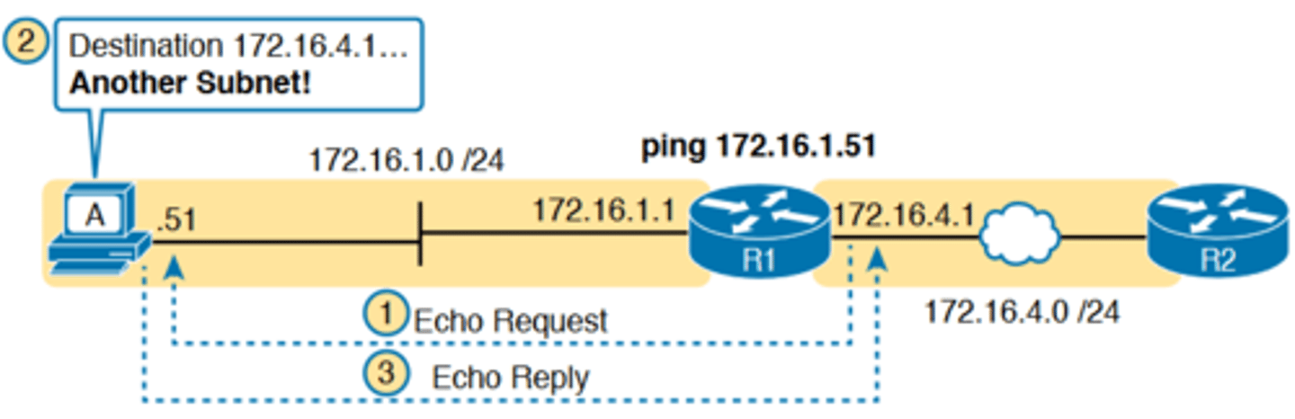
Testing LAN Neighbors with Extended Ping
-A standard ping of a LAN host from a router does not test that host's default router setting. However, an extended ping can test the host's default router setting
-Both tests can be useful, especially for problem isolation, because
■ If a standard ping of a local LAN host works...
■ But an extended ping of the same LAN host fails...
■ The problem likely relates somehow to the host's default router setting
standard vs extended ping
-As a standard ping command, R1 used its LAN interface IP address (172.16.1.1) as the source of the ICMP Echo
-So, when the host (A) sent back its ICMP echo reply, host A considered the destination of 172.16.1.1 as being on the same subnet
-Host A's ICMP echo reply message, sent back to 172.16.1.1, would work even if host A did not have a default router
setting at all!
-An extended ping from local Router R1, using R1's S0/0/0 IP address of 172.16.4.1 as the source of the ICMP echo request, means that host A's ICMP echo reply will flow to an address in another subnet, which makes host A use its default router setting
-Sometimes, the temptation is to connect to a router and
ping the host on the attached LAN, and it works. So, the engineer moves on, thinking that the network layer issues between the router and host work fine, when the problem still exists with the host's default router setting
Extended ping Command Does Test Host A's Default Router Setting
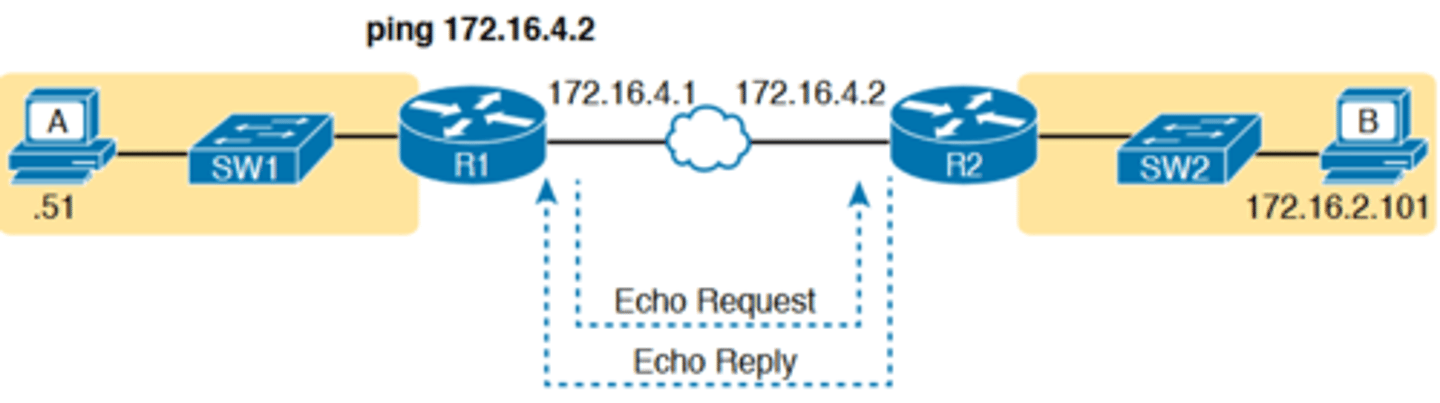
Pinging Across a WAN Link
-a standard ping test between routers over a serial or Ethernet WAN link tests whether the link can pass IPv4 packets
-A successful ping of the IP address on the other end of an Ethernet WAN link that sits between two routers confirms several specific facts, such as the following:
■ Both routers' WAN interfaces are in an up/up state.
■ The Layer 1 and 2 features of the link work.
■ The routers believe that the neighboring router's IP address is in the same subnet.
■ Inbound ACLs on both routers do not filter the incoming packets, respectively.
■ The remote router is configured with the expected IP address (172.16.4.2 in this case).
Using Ping with Names and with IP Addresses
-the ping command can use hostnames, and pinging a hostname allows the network engineer to further test whether the Domain Name System (DNS) process works
-First, most every TCP/IP application today uses hostnames rather than IP addresses to identify the other device.
-before a host can send data to a specific IP address, the host must first ask a DNS server to resolve that hostname into the matching IP address
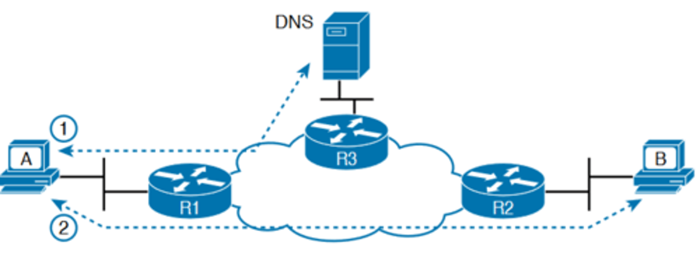
DNS Name Resolution by Host A
-a ping B command on host A tests A's DNS settings, as shown in Figure 18-10
-When host A sees the use of a hostname (B), it first looks in its local DNS name cache to find out whether it has already resolved the name B
-If not, host A first asks the DNS to supply (resolve) the name
into its matching IP address (Step 1 in the figure)
-Only then does host A send a packet to 172.16.2.101, host B's IP address (Step 2)
-a classic comparison is to first ping the destination host using the hostname, which requires a DNS request. Then, repeat the same test, but use the destination host's IP address instead of its name, which does not require the DNS request
-If the ping of the hostname fails but the ping of the IP address works, the problem usually has something to do with DNS
Problem Isolation Using the traceroute Command
Like ping, the traceroute command helps network engineers isolate problems. Here is a comparison of the two:
■ Both send messages in the network to test connectivity.
■ Both rely on other devices to send back a reply.
■ Both have wide support on many different operating systems.
■ Both can use a hostname or an IP address to identify the destination.
■ On routers, both have a standard and extended version, allowing better testing of the reverse route
-The biggest differences relate to the more detailed results in the output of the traceroute command and the extra time and effort it takes traceroute to build that output
traceroute Basics
-Although the ping command can prove helpful in isolating the source of the problem, the traceroute command may be a better option
-The traceroute command systematically helps pinpoint routing problems by showing how far a packet goes through an IP network before being discarded
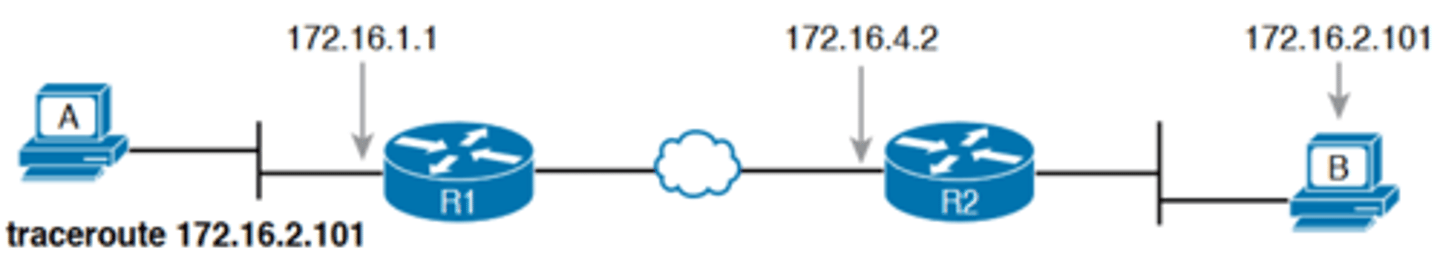
-The traceroute command identifies the routers in the path from source host to destination host. Specifically, it lists the next-hop IP address of each router that would be in each of the individual routes
-For instance, a traceroute 172.16.2.101 command on host A in Figure 18-11 would identify an IP address on Router R1, another on Router R2, and then host B, as shown in the figure
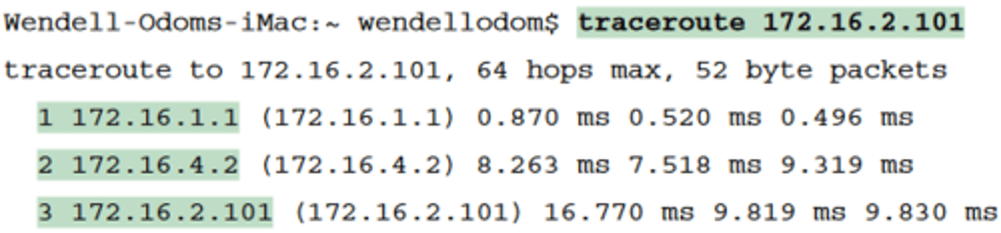
Output from traceroute 172.16.2.101 on Host A
TTL
-IPv4 routers defeat routing loops in part by discarding looping IP packets
-To do so, the IPv4 header holds a field called Time To Live (TTL). The original host that creates the packet sets an initial TTL
value. Then each router that forwards the packet decrements the TTL value by 1. When a router decrements the TTL to 0, the router perceives the packet is looping, and the router discards the packet
-The router also notifies the host that sent the discarded packet by sending an ICMP TTL Exceeded message
How the traceroute Command Works
-The traceroute command gathers information by generating packets that trigger error messages from routers; these messages identify the routers, letting the traceroute command
list the routers' IP addresses in the output of the command
-That error message is the ICMP Time-to-Live Exceeded (TTL Exceeded) message, originally meant to notify hosts when a
packet had been looping around a network
-Traceroute sends messages with low TTL values to make the routers send back a TTL Exceeded message. Specifically, a traceroute command begins by sending several packets (usually three), each with the header TTL field equal to 1
-When that packet arrives at the next router—host A's default Router R1 in the example of Figure 18-12—the router decrements TTL to 0 and discards the packet. The router then sends host A the TTL Exceeded message, which identifies the router's IP address to the traceroute command

TTL=2 Message Sent by traceroute
-The traceroute command sends several TTL=1 packets, checking them to see whether the TTL Exceeded messages flow from the same router, based on the source IP address of the TTL Exceeded message
-Assuming the messages come from the same router, the traceroute command lists that IP address as the next line of output on the command.
-To find all the routers in the path, and finally confirm that packets flow all the way to the destination host, the traceroute command sends a small set of packets with TTL=1, then a
small set with TTL=2, then 3, 4, and so on, until the destination host replies
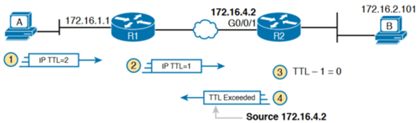
TTL=2 Message Sent by traceroute cont.
-Figure 18-13 shows the packet from the second set with TTL=2. In this case, one router (R1) actually forwards the packet, while another router (R2) happens to decrement the TTL to 0, causing a TTL Exceeded message to be sent back to host A
The figure shows these four steps:
1. The traceroute command sends a packet from the second set with TTL=2.
2. Router R1 processes the packet and decrements TTL to 1. R1 forwards the packet.
3. Router R2 processes the packet and decrements TTL to 0. R2 discards the packet.
4. R2 notifies the sending host of the discarded packet by sending a TTL Exceeded ICMP message. The source IP address of that message is 172.16.4.2
-Most routers use simpler logic that also makes command output like traceroute more consistent and meaningful
-That logic: choose the TTL Exceeded message's source IP address based on the source interface of the original message that was discarded due to TTL
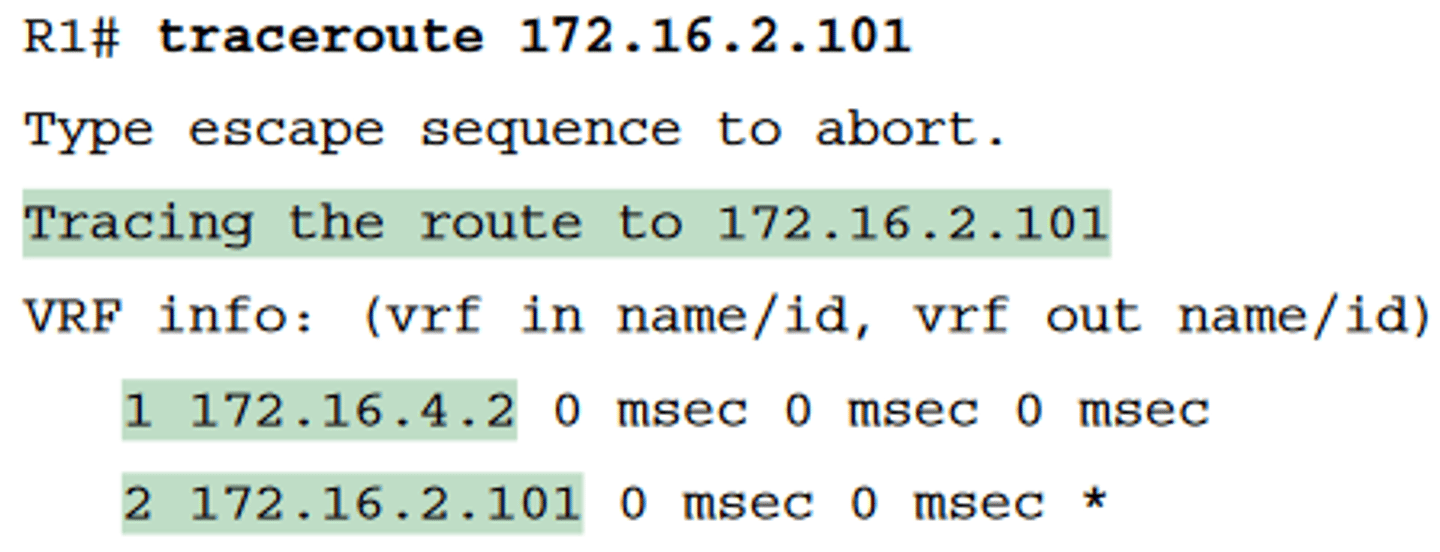
Standard traceroute
-Example 18-5 lists the output of a standard traceroute command on Router R1
-Like the standard ping command, a standard traceroute command chooses an IP address based on the outgoing interface for the packet sent by the command
-So, in this example, the packets sent by R1 come from source IP address 172.16.4.1, R1's G0/0/0 IP address
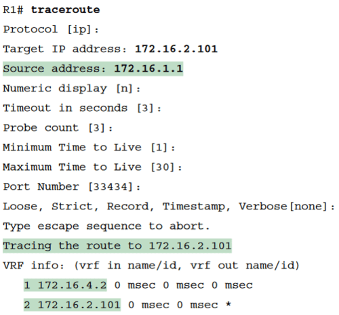
Extended traceroute
-The extended traceroute command, as shown in Example 18-6, follows the same basic command structure as the extended ping command
-The user can type all the parameters on one command line, but it is much easier to just type traceroute, press Enter, and let IOS prompt for all the parameters, including the source IP address of the packets (172.16.1.1 in this example).
traceroute on different OS
-Both the ping and traceroute commands exist on most operating systems, including Cisco IOS
-most Windows operating systems support tracert and pathping, and not traceroute. Linux and OS X support the traceroute command
Common Reasons to Use the IOS Telnet and SSH Client
-in some cases, you may want to take advantage of the Telnet and SSH client built in to IOS on the routers and switches to Telnet/SSH from one Cisco device to the next.
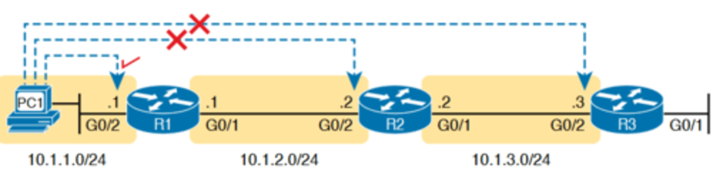
-To understand why, consider the example shown in Figure 18-14. The figure shows arrowed lines to three separate IP addresses on three separate Cisco routers
-PC1 has attempted to Telnet to each address from a different tab in PC1's Telnet/SSH client. However, R2 happens
to have an error in its routing protocol configuration, so R1, R2, and R3 fail to learn any routes from each other. As a result, PC1's Telnet attempt to both 10.1.2.2 (R2) and 10.1.3.3 (R3) fails
-In some cases, like this one, a Telnet or SSH login from the network engineer's device can fail, while you could still find a way to log in using the telnet and ssh commands to use the
Telnet and SSH clients on the routers or switches
-With this particular scenario, all the individual data links work; the problem is with the routing protocol exchanging routes
Successive Telnet Connections: PC1 to R1, R1 to R2, and R2 to R3
-PC1 can ping R1's 10.1.1.1 IP address, R1 can ping R2's 10.1.2.2 address, and R2 can ping R3's 10.1.3.3 address
-Because each link works, and each router can send and receive packets with its neighbor on the shared data link, you could Telnet/SSH to each successive device
-Figure 18-15 shows the idea. On the left, PC1 begins with either a Telnet/SSH or a console connection into Router R1, as shown on the left
-Then the user issues the telnet 10.1.2.2 command from R1 to Telnet to R2. Once logged in to R2, the user can issue commands on R2
-Then from R2, the user could issue the telnet 10.1.3.3 command to Telnet to R3, from which the user could issue commands on R3
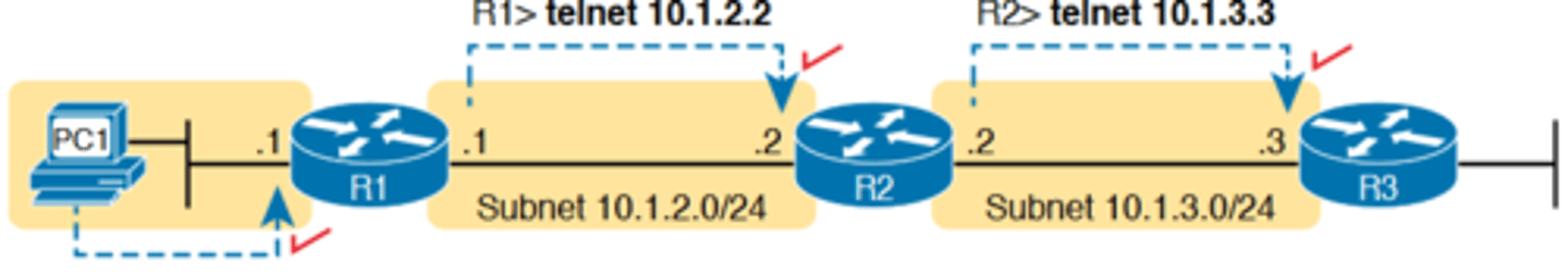
Telnet cont.
-The Telnet connections shown in Figure 18-15 work because each Telnet in this case uses source and destination addresses in the same subnet.
-Because each of these telnet commands connects to an IP address in a connected subnet, the routing protocol could be completely misconfigured, and you could still Telnet/SSH to each successive device to troubleshoot and fix the problem
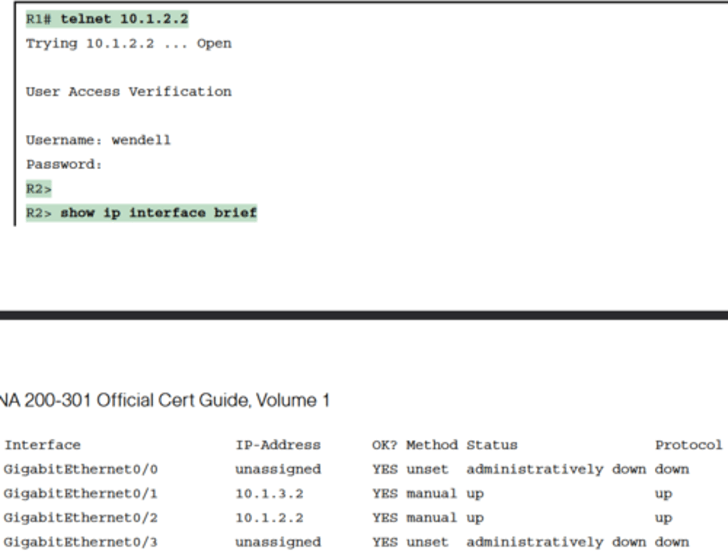
IOS Telnet and SSH Examples
-Using the IOS Telnet client via the telnet host command is pretty simple. Just use the IP address or hostname to identify the host to which you want to connect, and press Enter
-After issuing the telnet 10.1.2.2 command, R2 asks the user for both a username and password because Router R2 uses local
username authentication, which requires those credentials
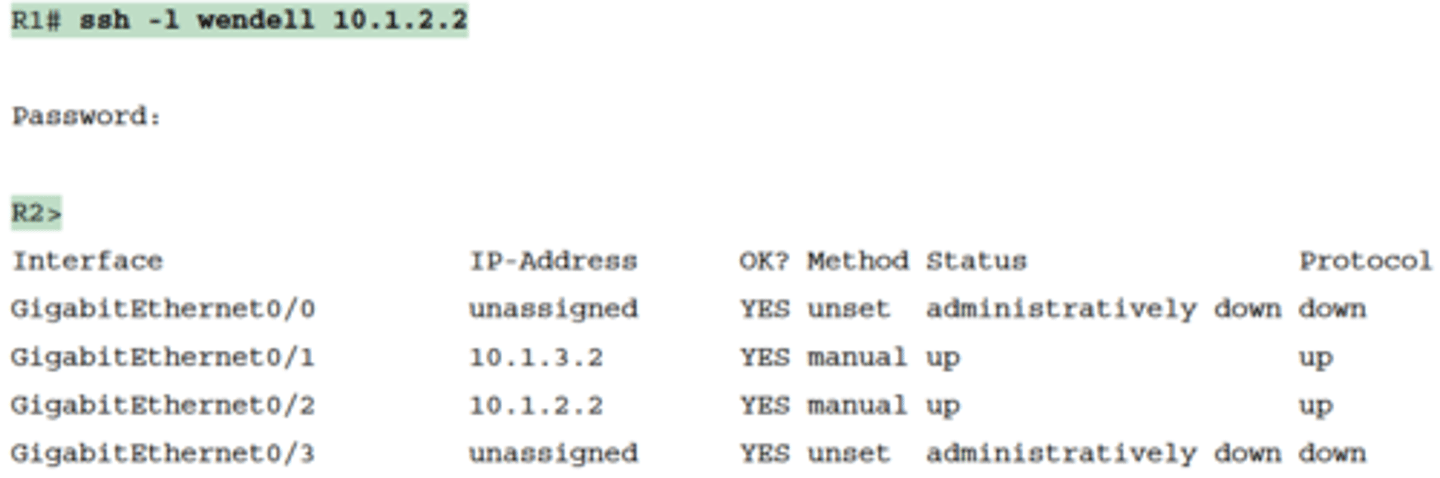
SSH Client from R1 to R2 to View Interface Status on R2
-The ssh -l username host command in Example 18-8 follows the same basic ideas as the telnet host command, but with an SSH client
-The -l flag means that the next parameter is the login username
-In this case, the user begins logged in to Router R1 and then uses the ssh -l wendell 10.1.2.2 command to SSH to Router R2
-R2 expects a username/password of wendell/odom, with wendell supplied in the command and odom supplied when R2 prompts the user
-When you have finished using the other router, you can log out from your Telnet or SSH connection using the exit or quit command
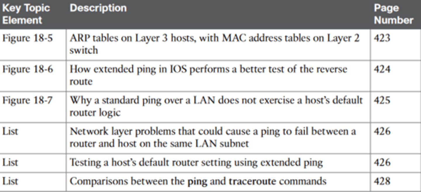
Key Topics
Key Terms
ping, traceroute, ICMP echo request, ICMP echo reply, extended ping, forward route, reverse route, DNS