AOP-101 (1) Rapid Power Reduction
1/27
There's no tags or description
Looks like no tags are added yet.
Name | Mastery | Learn | Test | Matching | Spaced |
|---|
No study sessions yet.
28 Terms
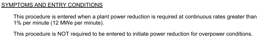
Entry Condtions
Power Reduction Greater than 12MWe/min
*This AOP is NOT required to be entered to initiate a power reduction during overpower conditions
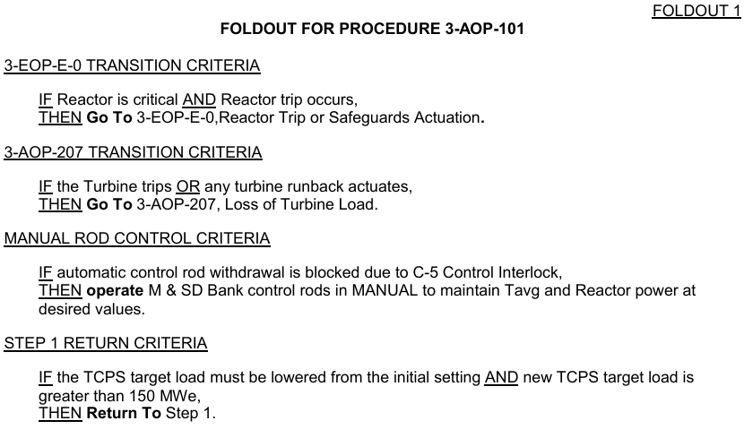
Foldout Page Criteria
(4)
E-0 Transition
If Reactor Trip: Go To E-0
AOP-207 Transition
If Turbine Trip OR Runback: Go To AOP-207
Manual Rod Control
IF auto-movement blocked by C-5: Operate in MANUAL
Step 1 Return
IF TCPS target load changes AND still >150MWe: Return Step 1
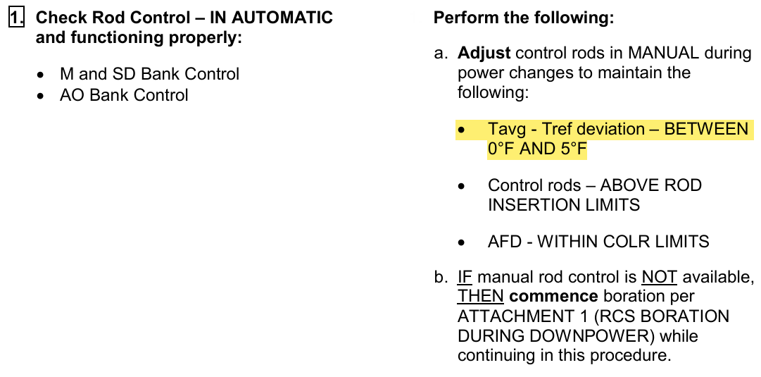
Rods in Manual Temperature band
(Step 1)
Deviation between 0 - 5°F
Reduce Generator Load Method and Alternate
(Step 2 and RNO)
Ensure Megawatt IN, then go
Toggle Manual Runback to 250MW/min (normally 2500)
*Manual Fails = Trip Turbine, Go To AOP-207
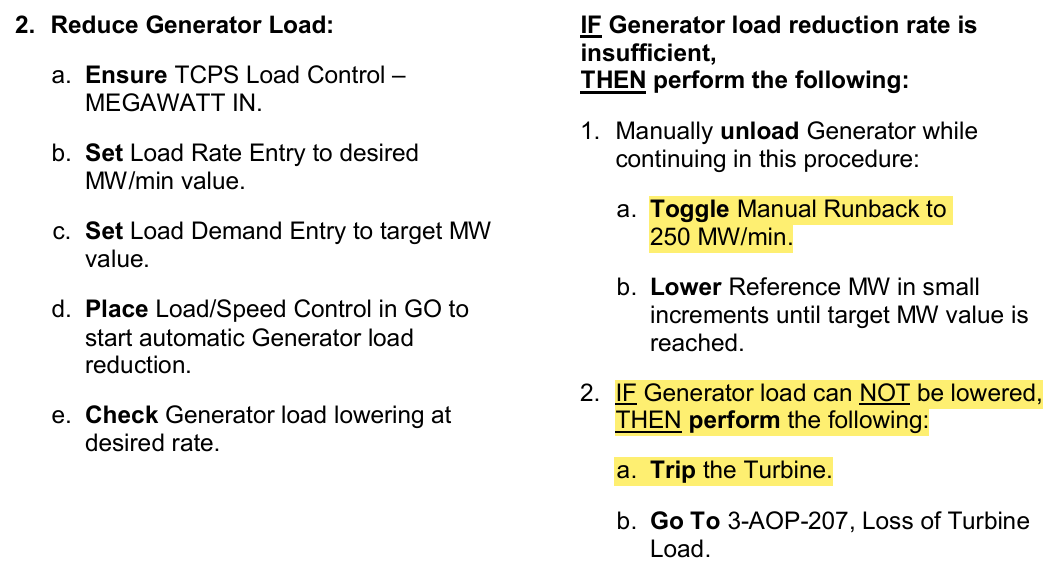
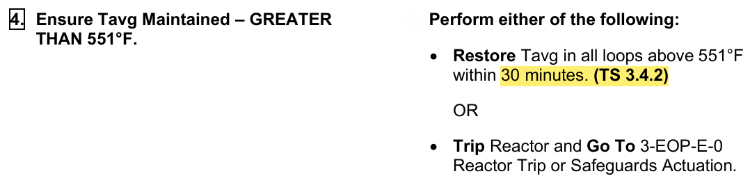
Options if Tavg NOT maintained >551°F
(Step 4 and RNO)
Restore to >551°F within 30min
Go To E-0
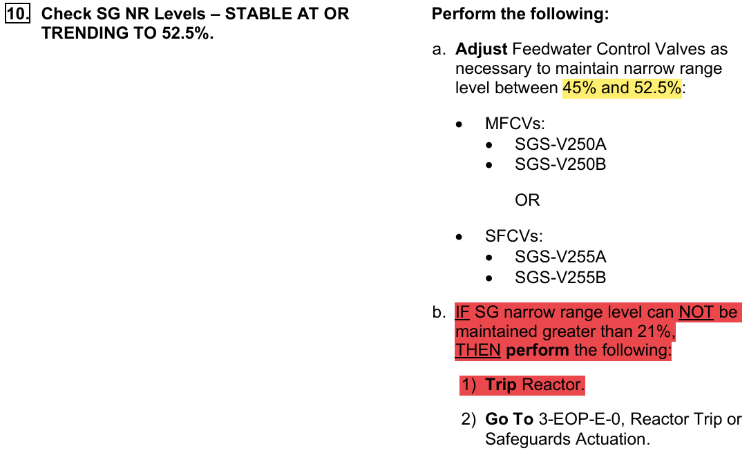
E-0 Requirement based on SG NR Level
(Step 10)
Step 10 RNO
IF cannot maintain greater than 21% NR
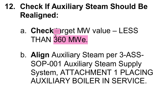
What Target Megawatt aligns Auxiliary Steam
(Step 12)
360 MWe (Approximately 30% Plant)
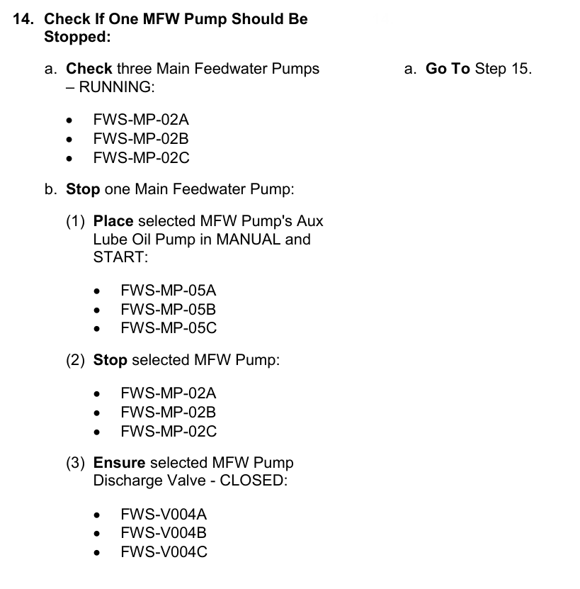
Securing a MFW Pump (First)
What Megawatt Target?
Sequence of steps to secure pump?
Less than 720MWe
Manual and Start of Aux LO pump
Stop MFW Pump
Ensure Discharge Valve closes
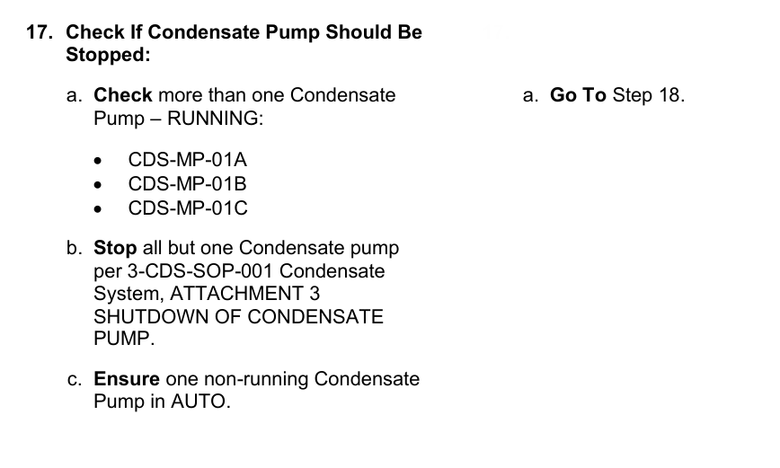
Securing a Condensate Pump
What Megawatt Target?
Sequence of steps to secure pump?
(Step 16 & 17)
Less than 480MWe
Per SOP
Securing a MFW Pump (Second)
What Megawatt Target?
Sequence of steps to secure pump?
(Step 19 & 20)
Less than 360MWe
Manual and Start of Aux LO pump
Stop MFW Pump
Ensure Discharge Valve closes
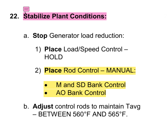
What Target Megawatt are Rods placed in Manual and Steam Dumps moved to Pressure Mode
(Step 21 & 22)
Less than 240 MWe
Basis Step 1
What GFES factor causes positive reactivity addition during Turbine Load reduction?
Power Defect
Basis Step 2
At what ramp rate could Bypass Valves open?
Is this desirable?
>60MWe/min (5%/min)
Operation of bypass valves will NOT assist REACTOR power lowering, however if the objective is to lower TURBINE power steam dumps will NOT impede reduction therefore a faster manual runback may be desirable
Basis Step 2 Note 2
What should your INITIAL MWe target be during reduction?
>150MWe
“target of 150MWe can complicate Tavg controller later”
Step 2 Basis
Why do we use Megawatt IN during load reduction?
“Provides a rate and fine tuning component to coarser load controller setting” (Finer control)
Step 16 Basis
When do we realign MSR reheater scavenging steam vents?
What is high/low power destination of vent paths?
When the down power reaches 480MWe (40%RTP) Just before stopping a Condensate Pump
*Seems to be some confliction with Step 18 basis based on 40% vs. 32% not sure if it’s important enough
High: Feedwater Heaters for plant efficiency
Low: Condenser
Step 25 Basis
If the Main Generator is the only source of power to the UATs, when will the RATs be aligned to ES buses?
PRIOR to opening the Main Generator Output Breaker (Turbine Trip)
*Manually transfer ES buses instead of foolishly relying on a residual bus transfer to complicate the transient
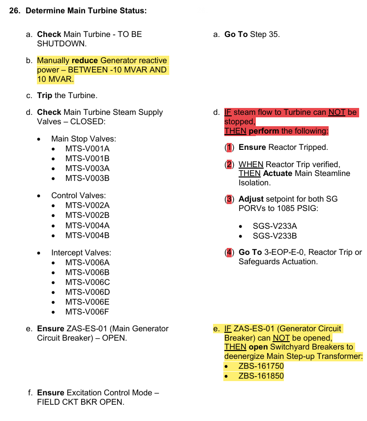
Step 26 Basis
What is status of Real and Reactive Power when tripping the turbine?
Why is Reactive power changed to this load?
Real: <15% Turbine Load (150MWe)
Reactive: ±10MVAR
Minimize effects to Grid on trip
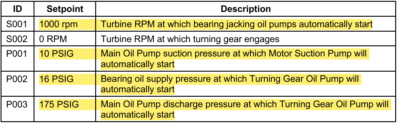
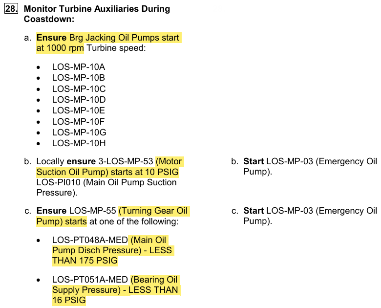
Turbine Auxiliaries Refresher during coast down
Jacking Oil Pump Start
MSOP Start
TGOP Start (Bearing Oil pressure)
TGOP Start (Main Oil Pump discharge pressure)
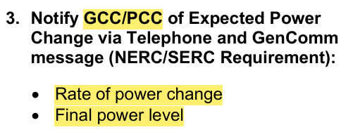
GCC Notification Requirements
(Step 3)
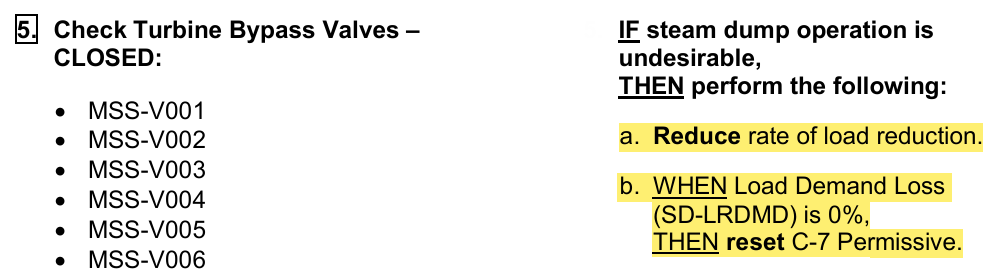
How to Close Bypass Valves?
(Step 5)
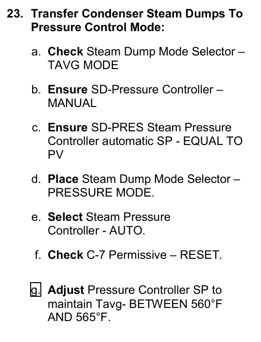
Transferring Steam Dumps to Pressure Control Mode
(Step 23)
Notice, Rods already in MANUAL per previous step
Basis:
Since RCS temperature control is more flexible and can be more precise in the Pressure Control Mode than in Tavg Mode, the Pressure Control Mode is preferred at this time.
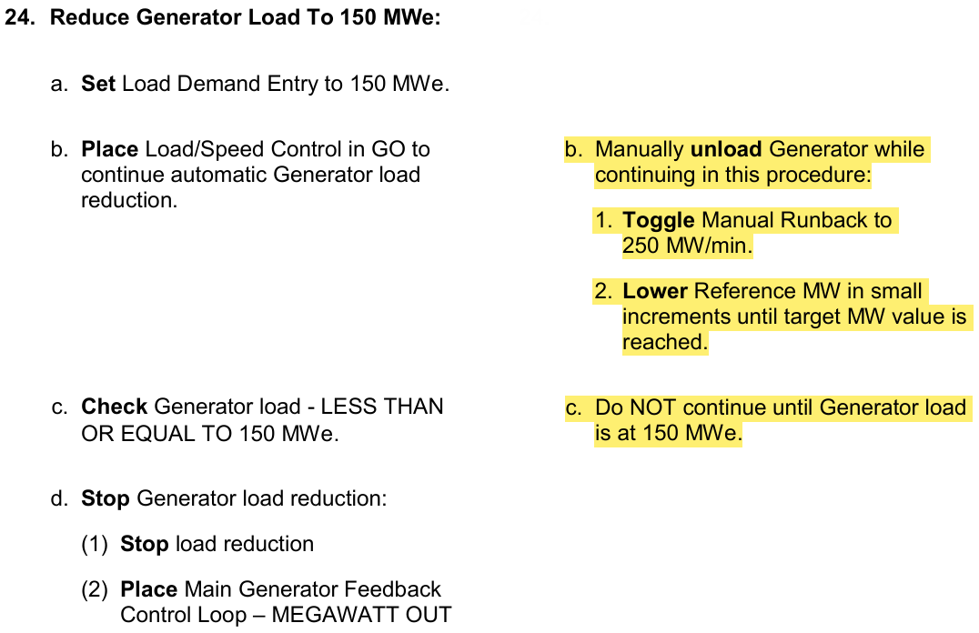
Lowering power below 150MWe
(Step 24 and RNO)
MVAR Status when Tripping Turbine
Actions to take if Turbine Trip unsuccessful
(Step 26)
Refresher
Turbine Coast down
(Step 28)
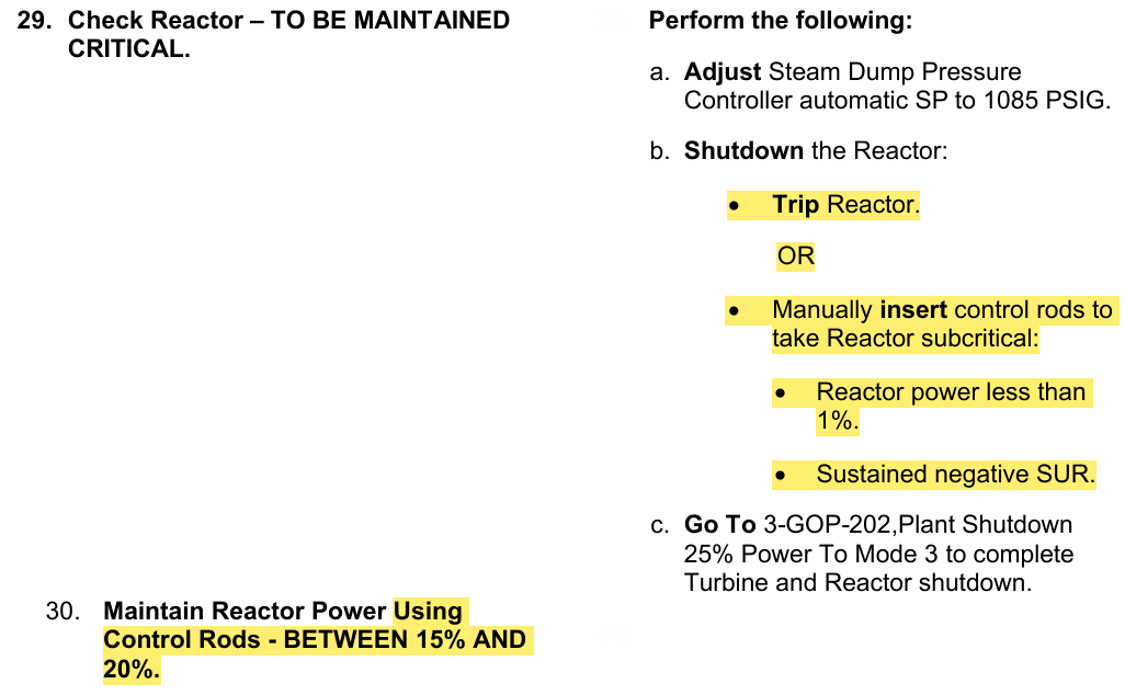
How to maintain a Critical Reactor or Shutdown the Reactor
(Step 29 & 30)
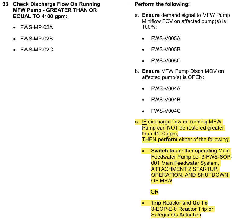
Maintaining FWS with the Reactor Critical
(Step 33)
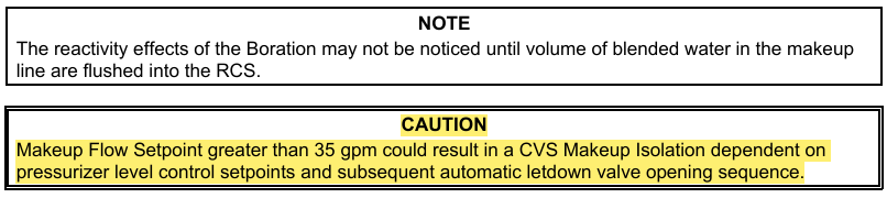
Attachment 1 RCS Boration during Downpower
Note and Caution
(Step 1)