OSI Model (Section 3)
1/26
There's no tags or description
Looks like no tags are added yet.
Name | Mastery | Learn | Test | Matching | Spaced | Call with Kai |
|---|
No study sessions yet.
27 Terms
OSI Model Layers
■ Physical - Layer 1 - Bits
■ Data Link - Layer 2 - Frames
■ Network - Layer 3 - Packets
■ Transport - Layer 4 - Segments
■ Session - Layer 5 - Data
■ Presentation - Layer 6 - Data
■ Application - Layer 7 - Data
Physical Layer
1st layer of the OSI model where transmission of bits across the network occurs and includes physical and electrical network characteristics
Data type occurs as bits (Binary bits represented as a series of 1s and 0s)
Cables are also part of the physical layer.
Examples of Layer 1 Devices:
Layer 1 devices are essentially repeaters, passing along whatever is received. (Dumb devices)
Cables (Fiber optic cable, Ethernet cable, Coaxial cable)
Wireless (Bluetooth, Wi-Fi, Near Field Communication (NFC))
Infrastructure Devices (Hubs, Access Points, Media Converters)
Transition Modulation
Occurs in Layer 1 (Physical Layer)
Switching between levels to represent 1 or 0
Copper Wire (Cat5/Cat6) – Uses voltage (0V for 0, +5V/-5V for 1)
Fiber Optic Cable – Uses light (on for 1, off for 0)
Synchronization (Layer 1)
Asynchronous Communication: Start and stop bits for out-of-sync data transmission.
Synchronous Communication: Real-time communication using a common time source
Bandwidth Utilization (Layer 1)
Broadband: Divides bandwidth into separate channels (e.g., cable TV)
Baseband: Uses all frequencies of the cable all the time (e.g., telephone)
Multiplexing (Layer 1)
Multiplexing enables simultaneous usage of a baseband connection by multiple users.
Multiplexing involves optimizing a limited amount of resources for more efficient utilization.
Time division multiplexing (TDM): Each session takes a turn, using time slots, to share the medium between all users.
Statistical time-division multiplexing (StatTDM): Dynamically allocates the time slots on an as-needed basis.
Frequency division multiplexing (FDM): Divides the medium into channels based on frequencies and each session is transmitted over a different channel.
Data Link Layer
2nd layer of OSI Model
Responsible for packaging bits from Layer 1 into frames and transmitting them across the network.
Performs error detection and correction, identifies devices using MAC addresses, and provides flow control.
Examples of Layer 2 devices:
Network Interface Cards
Bridges
Switches
Switch Operation:
Switches use CAM tables with MAC addresses to identify physical ports connected to devices
Enables selective data transmission to specific areas in the network.
MAC (Layer 2)
Media Access Control (MAC)
A means for identifying a device physically and allowing it to operate on a logical topology (Ex. D2:51:F1:3A:34:65)
A unique 48-bit physical addressing system is assigned to every network interface card (NIC) produced ● Written in hexadecimal numbers
First 24 bits – identify the manufacturer
Remaining 24 bits – identify the specific device
Crucial for logical topology – identifying devices on the network
Logical Link Layer (LLC) (Layer 2)
Provides connection services and acknowledges message receipt, ensuring controlled data flow
LLC is the most basic form of flow control (Limits data sent by a sender and prevents receiver overwhelm)
Provides basic error control functions
Uses a checksum to detect corrupted data frames
Synchronization Methods at Layer 2
Isochronous Mode
Common reference clock
Time slots for transmissions
Less overhead
Synchronous Method
Devices use the same clock, with beginning and ending frames, and control characters for synchronization
Asynchronous
Devices reference own clock cycles
No strict control over communication timing
Network Layer
3rd Layer of the OSI Model
Concerned with routing and forwarding traffic using logical addresses
Examples of Layer 3 devices:
Routers
Multi-layer switches (switches are always considered a layer 2 device unless it is multi-layered)
Layer 3 Protocols:
IPv4
IPv6
Internet Control Message Protocol (ICMP)
(IP and routers are commonly encountered Layer 3 devices in exams)
How is data routed across a network? (Network Layer 3)
Packet switching: Data is divided into packets and then forwarded. Most networks use packet switching.
Circuit switching: Dedicated communication link is established between two devices. In circuit switching, a dedicated and constant communication path is maintained for the duration of a conversation.
Message switching: Data is divided into messages which may be stored and then forwarded.
Route Discovery & Selection (Network Layer 3)
Routers maintain routing tables for determining the best path
Manually configured as a static route or dynamically through a routing protocol.
Routing protocols help us decided how data is going to flow across the network and how the routers are going to communicate that information
Types of routing protocols: RIP, OSPF, EIGRP
ICMP
Internet Control Message Protocol
Occurs in Network Layer 3
Used for sending error messages and operational information to an IP destination
PING
Most commonly used ICMP
Helps troubleshoot network issues by testing connectivity and response times
Traceroute
Traces the route of a packet through the network
Transport Layer
4th Layer of the OSI Model
Dividing line between the upper layers and the lower layers of the OSI model
Deals with segments and datagrams
2 important protocols: TCP & UDP
2 reliability features: Windowing & Buffering
TCP works with segments
UDP works with datagrams
Examples of Layer 4 Devices:
TCP & UDP
WAN accelerators
Load balancers and firewalls
TCP
Transmission Control Protocol
Occurs in Transport Layer 4
Connection-oriented protocol that is a reliable way to transport segments across the network.
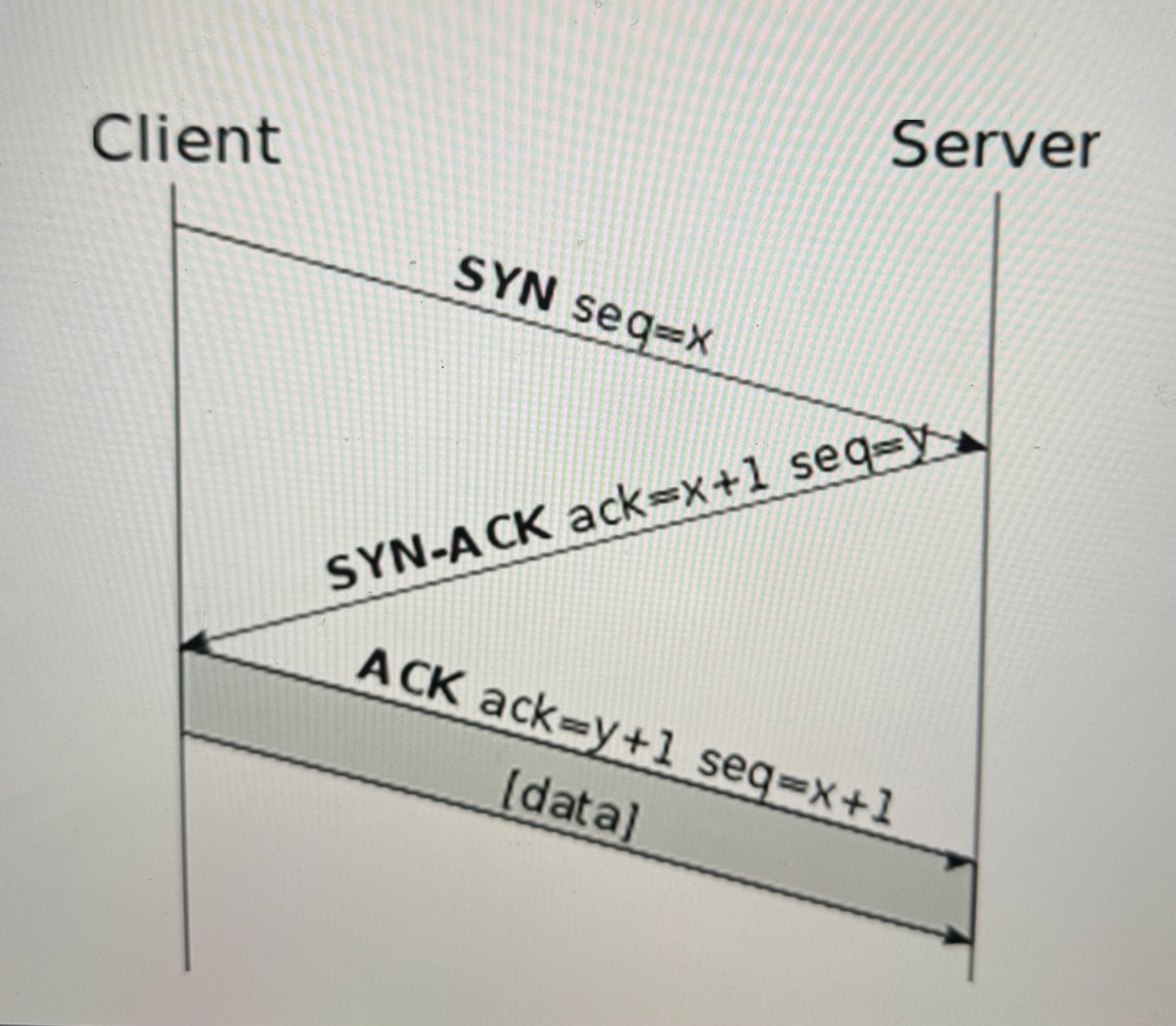
Uses Three-Way Handshake
SYN – synchronization
SYN-ACK – synchronization - acknowledgement
ACK – acknowledgement
Windowing for flow control
Used for all network data that needs to be assured to get to its final destination
UDP
User Datagram Protocol
Occurs in Transport Layer 4
A connectionless protocol that is an unreliable way to transport segments (datagram)
Used for audio and visual streaming
No three-way handshake and less overhead
No acknowledgment or retransmission
TCP Vs. UDP
TCP:
Reliable
Uses Three-way Handshake
Connection-oriented
Segment retransmission and flow control through windowing
Sequencing
Acknowledgment of segments
UDP:
Unreliable
No Three-way Handshake
Connectionless
No retransmission and no windowing
No sequencing
No acknowledgment of datagrams
Windowing (Transport Layer 4)
Allows clients to adjust the amount of data in each segments during transmission
Optimize throughput and bandwidth
Open or close window based on retransmissions
Buffering (Transport Layer 4)
Occurs when devices allocate memory to store segments if bandwidth is not readily available
Buffer: Temporary storage for segments
Prevents overflow by clearing segments
Session Layer
5th Layer of the OSI Model
Manages sessions, ensuring separate conversations to prevent data intermingling
Setting Up Session
Checking of user credentials and assigning numbers to sessions to help identify
Maintaining Session
Continuous data transfer between parties
If the connection breaks, it will require re-establishment
Includes acknowledgement of data
Tearing Down a Session
Ending a session once communication goals are achieved
Mutual agreement or one party disconnects
Layer 5 Devices & Protocols:
H.323
Used for setting up, maintaining, and tearing down voice and video connections
Operates over the real-time transport protocol (RTP)
NetBIOS
Utilized by computers for file sharing over a network
Commonly associated with Windows file sharing
Layer 5 issues involve protocols and software rather than specific devices
Presentation Layer
6th Layer of the OSI Model
Responsible for formatting data for exchange and securing it through encryption
Data Formatting: Formatting data by a computer to have compatibility between different devices
American Standard Code for Information Interchange (ASCII) ○ Text-based language to use
Ensures data is readable by receiving system
Provides proper data structures
Negotiates data transfer syntax for the Application Layer (Layer 7)
Examples of Devices at Layer 6:
Scripting Languages (HTML, MXL, etc.)
Standard Text (ASCII, Unicode,EBCDIC, etc.)
Pictures (JPG, GIF, PNG, etc.)
Movie Files (MOV, MPG, etc.)
Encryption Algorithms (TLS, SSL…)
Encryption (Presentation Layer 6)
Used to scramble data in transit to keep it secure and provide data confidentiality
Transport Layer Security (TLS)
Ensures secure data transfer
Creates an encrypted tunnel, protecting sensitive information
Application Layer
7th Layer of the OSI Model
Provides application-level services where users communicate with the computer
Focus on lower-level applications
File transfer
Network transfer
Application Services unify communication components from multiple network applications.
Service Advertisement: Sending out announcements to other devices on the network to state the services they offer.
Layer 7 Protocols:
Email Applications
POP3
IMAP
SMTP
Web Browsing
HTTP
HTTPS
Domain Name Services (DNS)
File Transfer Protocols
FTP
FTPS
SFTP
Remote Access
Telnet
SSH
SNMP
Encapsulation and Decapsulation
Occurs in Application Layer 7
Encapsulation: Process of putting headers and sometimes trailers around data
Decapsulation: Removing the applied encapsulation to access the original data
OSI Model Layers
Moving down from Layer 7 to 1 – encapsulation
Moving up from Layer 1 to 7 – decapsulation
Data Transmission:
Encapsulation of data and adding a header at each layer
Layer 4 – source/destination ports
Layer 3 – source/destination IP addresses
Layer 2 – soure/destination MAC addresses
Layer 1 – data transmitted as 1s and 0s
Decapsulation at each intermediate device until the final host is reached
Final host decapsulates to Layer 7 for application understanding
Protocol Data Unit (PDU)
A single unit of information transmitted in a computer network ●
Terminology used for each layer is written as L(layer number) PDU
○ Example – L7 PDU for Layer 7
There are special names for the PDUs for layers 1, 2, 3, and 4
Layer 1 – Bits
Layer 2 – Frames
Layer 3 – Packets
Layer 4 – Segments (TCP) or Datagrams (UDP)