Three Phase Diode Rectifiers
1/4
There's no tags or description
Looks like no tags are added yet.
Name | Mastery | Learn | Test | Matching | Spaced |
|---|
No study sessions yet.
5 Terms
How do you create a full wave three-phase diode rectifier
If we can create a full-wave rectifier for a single-phase source, it seems logical that the same can be achieved for a three-phase source by providing conduction paths for periods of negative source voltage.
What is the notable difference between the half wave and full wave rectifiers?
There is a notable difference between the half-wave and full-wave rectifiers: the voltages of interest are the line-line voltages as there is no neutral point applied to the load. The bias of any given diode is therefore determined by the six line-line voltages, resulting in six possible conduction pairs which switch in an order determined by the phase order. In the figures above, phase A leads phase B which leads phase C.
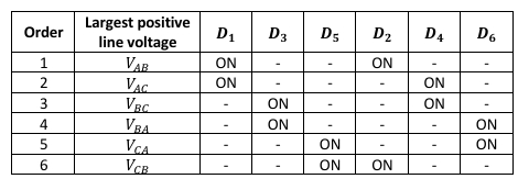
What is the switching pattern for a full wave three phase diode rectifier
Mathematically, each dominant line voltage conducts for 𝜋3 ⁄ radians so the average voltage can be calculated across this period. Considering Phase A (red) in the waveforms above, conduction is from 𝜋3 ⁄ to 2𝜋3 ⁄ .
Average voltage for the three-phase full-wave diode rectifier can be?
2.34𝑉𝑝ℎ

How do you increase further voltage smoothing
connecting a capacitor in parallel with the output