SPI III: Test 4 - Pulse-Echo Instrumentation & Artifacts
1/96
There's no tags or description
Looks like no tags are added yet.
Name | Mastery | Learn | Test | Matching | Spaced | Call with Kai |
|---|
No analytics yet
Send a link to your students to track their progress
97 Terms
M mode
motion mode; depth in vertical axis
M mode
depth is vertical
time is horizontal
M mode
combines A mode and B mode to show motion
since it shows brightness, it can also be considered B mode
B mode
B scan or brightness mode (gray scale sonography)
2D or 3D
A mode
amplitude mode
used in opthamology
A mode
depth (time) is horizontal
amplitude is vertical
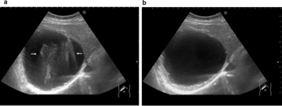
slice thickness/partial volume artifact
beam width perpendicular to the scan plane is greater than 2 adjacent reflectors and displays as echoes within an anechoic structure
how to improve slice thickness artifact
using tissue harmonic imaging
speckle
granular appearance of images
what causes speckle?
interference of echoes from the distribution of scatterers in tissue
constructive speckle
echoes add together
destructive speckle
echoes completely or partially cancel out
reverberation
equally spaced reflections of diminishing amplitude with increased imaging depth
reverberation
reverberation
two or more strong reflectors cause multiple reflections
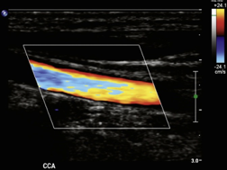
comet tail
twinkle (color)
ring down
type of reverberation that appears as multiple parallel lines or solid band behind a reflector
what causes ring down?
vibrations of air bubbles
ring down
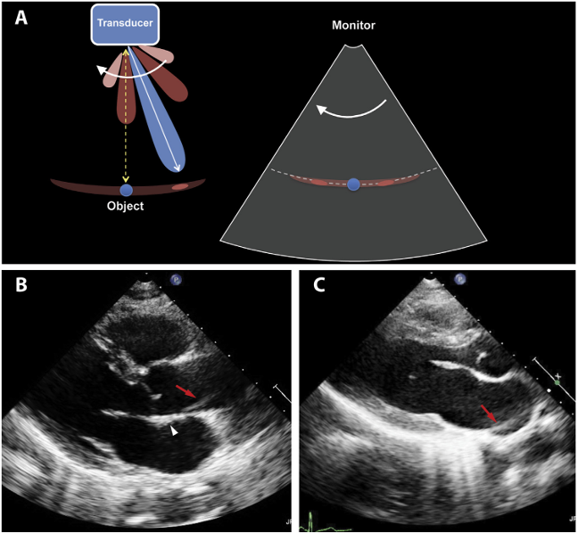
mirror image
form of reverberation where there’s a duplication of a structure on the opposite side of a strong reflector
where is mirror image common?
the pleura and diaphragm
also occurs in doppler
mirror image
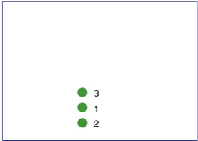
refraction
change of direction of the sound beam from one medium to the next
refraction
displays structures laterally from their correct locations
duplication
refraction
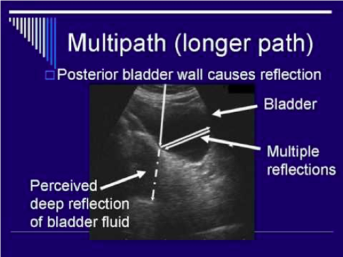
multipath artifact
displays structure deeper than it should be
multipath artifact
oblique incidence causes beam to reflect at an angle
multipath artifact
beam later reflects off another structure and echo takes longer to return (deeper)
multipath
focal banding
region of increased brightness at focal zone
what causes focal banding?
increased intensity of the beam
intensity = power / area
how to fix focal banding
adjust TGCs
focal banding
grating lobes
additional weaker beams emitted from an array transducer
side lobes
beams from a single element in different directions than the beam
grating lobes and side lobes
strong reflector duplicates structures laterally creating an arc appearance
grating lobes and side lobes
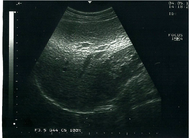
propagation speed error
occurs when the speed of sound in soft tissue is faster or slower than the assumed 1.54 mm/μs
explain this image about propagation speed error
reflector is actually here
slower speeds place echoes deeper - takes longer to return
faster speeds place echoes closer - returns sooner
range ambiguity
all echoes are not received before the next pulse is emitted
range ambiguity
places structures much closer to the surface than they should be; also occurs in doppler
what causes range ambiguity?
PRF is too high
range ambiguity
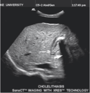
shadowing
weakening of echoes distal to:
strongly attenuating structure
strongly reflecting structure
from the edges of a refracting structure
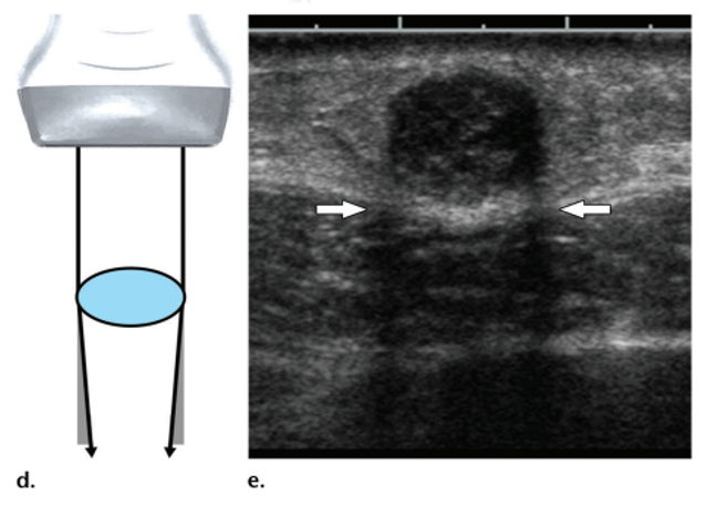
shadowing
what causes edge shadowing?
refraction along the edge of a curved structure that decreases intensity of sound posterior to the curved edge
edge shadowing
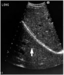
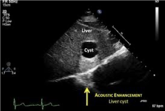
enhancement
strengthening of echoes distal to a weakly attenuating structure
enhancement
increased brightness behind a weakly attenuating structure
enhancement
how to reduce shadowing and enhancement
spatial compounding and other speckle reduction techniques
aliasing
flow exceeds velocity range & nyquist limit (PRF/2)
aliasing
appearance of doppler information (spectral or color) on the wrong side of the baseline
aliasing
how to reduce or eliminate aliasing
shift the baseline
increase the PRF
increase the doppler angle
use a lower operating f
use a CW device
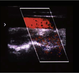
flash artifact
sudden burst of color doppler that demonstrates an extension of color beyond the region of blood flow
what causes flash?
typically tissue or transducer motion
how to reduce flash
increasing wall filter
flash
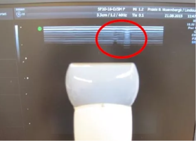
damaged crystal
gain
determines amount of amplification of echoes
ratio of output to input (dB)
time gain compensation (TGCs)
amplifies selectively based on arrival time (depth) and compensates for the effect of attenuation on an image
TGCs
allows for display of echoes from similar reflectors at different depths in a similar way
uniform brightness
dynamic range
ratio of largest to smallest amplitude or power a system can handle (dB)
image display
brightness is proportional to the echo strength
frame
each individual image
frame rate
number of images entered into memory per second
image memory
image frames are stored here
cine loop
storing the last several frames acquired before freezing
freeze
holding and displaying one frame out of a sequence
persistence
reduces noise and smooths the image by frame averaging
persistence
higher levels are appropriate for slow-moving structures
small (narrow) dynamic range
few shades of grey, black to white, high contrast
high (broad) dynamic range
more shades of grey (good contrast resolution)
edge enhancement
sharpens boundaries to make them more detectable and measurements more precise
write zoom
increases number of pixels or scan lines
frequency compounding
echo frequency spectrum is divided into frequency bands by filters, processed separately and then recombined
frequency compounding
can be adjusted to emphasize penetration, resolution, and tissue texture
frequency compounding
commonly used to reduce noise and improve contrast resolution
write zoom
increases number of pixels or scan lines
read zoom
number of pixels or scan lines is the same as the original image (can look like a reduction in pixels)
harmonic imaging
improves image quality by sending pulses of some frequency into the body but then imaging echoes of frequency double that sent in
how does harmonics improve image quality?
lateral resolution improvement
grating lobes are eliminated
superficial reverberation reduced or eliminated
panoramic imaging
expands the image beyond the normal limits of the field of view of the transducer
new echoes are added to the image in the direction in which the scan plane is moving
spatial compounding
averaging of frames that view anatomy from different angles
smoothes imaging surfaces and visualization of structures behind highly attenuating structures
how does spatial compounding improve image quality?
reduction in speckle and clutter artifacts
smooths imaging surfaces
visualization of structures behind a highly attenuating structure
coded excitation
uses a series of pulses and gaps, rather than a single driving pulse
coded excitation
ensembles of pulses drive the transducer to generate a single scan line
coded excitation
this approach accomplishes functions such as multiple foci, separation of harmonic echo bandwidth from transmitted pulse bandwidth, increased penetration, reduction of speckle with improved contrast resolution, and gray-scale imaging of blood flow
assumptions of the ultrasound system?
sound travels in a straight line
echoes originate only from objects located on the beam axis
the amplitude of the returning echoes is related directly to the reflecting or scattering properties of distant objects
the distance to reflecting or scattering objects is proportional to the round-trip travel time
gray-scale maps
assignment of specific display brightness to numbers retrieved from the memory
contrast resolution
the ability of a gray-scale display to distinguish between echoes of slightly different intensities
contrast resolution
depends on the number of bits per pixel in the image memory
temporal resolution
ability of a display to distinguish closely spaced events in time and to present rapid moving structures correctly
temporal resolution
dependent on the frame rate
if frame rate increases, this improves
if PRF increases, FR increases
what is the acoustic power determined by?
primarly the amplitude of the ultrasound wave
what does the thickness of the element affect?
the frequency
thicker element = lower frequency
thinner element = higher frequency
what does changing to a higher frequency transducer result in? and how does a sonographer compensate?
results in improved image resolution, with the pitfall being a decrease in depth penetration; sonographer compensates by selecting the correct frequency for the area of the body being scanned