Control Unit CpE 3202
1/68
There's no tags or description
Looks like no tags are added yet.
Name | Mastery | Learn | Test | Matching | Spaced | Call with Kai |
|---|
No analytics yet
Send a link to your students to track their progress
69 Terms
John Von Neumann
Contemporary computer designs are based on concepts developed by this man at the Institute for Advanced Studies, Princeton
Programming Concepts
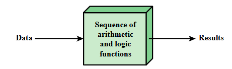
Hardwired systems are inflexible
General-purpose hardware can do different tasks, given correct control signals
Instead of re-writing, supply a new set of control signals
Programming in Hardware
Programming in Software
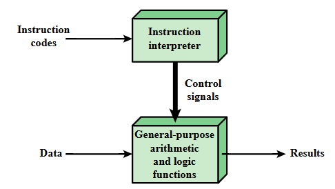
Software
A sequence of codes or instructions
Part of the hardware interprets each instruction and generates control signals
Provides a new sequence of codes for each new program instead of rewiring the hardware
Major Components
CPU
Instruction interpreter
Module of general-purpose arithmetic and logic functions
I/O Components
Input Module
Output Module
Input Module
Contains basic components for accepting data and instructions and converting them into an internal form of signals usable by the system
Output Module
Means of reporting results
Memory Address Register (MAR)
Specifies the address in memory for the next read or write
Memory Buffer Register (MBR)
Contains the data to be written into memory or receives the data read from memory
I/O Address Register (I/OAR)
Specifies a particular I/O device
I/O Buffer Register (I/OBR)
Used for the exchange of data between an I/O module and the CPU
PC (Program Counter)
A special register in a computer’s CPU or processor that contains the memory address (location) of the next program instruction to be executed
Also known as an instruction counter, instruction pointer, instruction address register or sequence control register
IR (Instruction Register)
An internal register in most CPUs into which the current instruction is loaded from main memory
Holds a machine instruction that is currently being executed or decoded by the CPU
2 Steps in Instruction Processing
The processor reads (fetches) instructions from memory one at a time
The processor executes each instruction
Fetch Cycle
The processor fetches an instruction from memory
PC (Program Counter) holds the address of the instruction to be fetched next
Processor increments the PC after each instruction fetch so that it will fetch the next instruction in sequence
Fetched instruction is loaded into the instruction register (IR)
Processor interprets the instruction and performs the required actionThe process by which the CPU retrieves an instruction from memory for execution, advancing the Program Counter (PC) to point to the next instruction.
Action Categories in Execute Cycle
Processor-memory
Processor-I/O
Control
Data processing
Processor-memory
Data transferred from processor to memory or from memory to processor
Processor-I/O
Data transferred to or from a peripheral device by transferring between the processor and an I/O Module
Control
An instruction may specify that the sequence of execution be alteredD
Data Processing
The processor may perform some arithmetic or logic operation on data
When fetching next instruction
ADDR ←- PC
IR ←- data from memory
Control Signals:
IOM = 1, RW = 0, OE = 1
When branching
PC ←- instruction address (instruction operand)
Control Signals:
IOM = X, RW = X, OE = X
When performing register-register operation
REG1 ←- REG2
Control Signals:
IOM = X, RW = X, OE = X
When reading data from data memory
MAR ←- Memory Address
BUS ←- Data from Memory
Control Signals:
IOM = 1, RW = 0, OE = 1
When writing data to data memory
MAR ←- memory address
Data Memory[address] ←- BUS
Control Signals:
IOM = 1, RW = 1, OE = 0
When reading data from I/O Memory
IOAR ←- Memory Address
BUS ←- Data from Memory
Control Signals:
IOM = 0, RW = 0, OE = 1
When writing data to I/O Memory
IOAR ←- Memory Address
I/O Memory[address] ←- BUS
Control Signals:
IOM = 0, RW = 1, OE = 0
Instruction Fetch (IF)
Read instruction from its memory location into the processor
Instruction Operation Decoding (IOD)
Analyze instruction to determine type of operation to be performed and operand(s) to be used
Operand Address Calculation (OAC)
If the operation involves reference to an operand in memory or available via I/O, then determine the address of the operand
Operand Fetch (OF)
Fetch the operand from memory or read it in from I/O
Data Operation (DO)
Perform the operation indicated in the instruction
Operand Store (OS)
Write the result into memory or out to I/O
Interrupts
Mechanism by which other modules may interrupt normal sequence processing
Provided to improve processing efficiency
Classes of Interrupts
Program
Timer
I/O
Hardware Failure
Program
Generated by some condition that occurs as a result of an instruction execution, such as arithmetic overflow, division by zero, attempt to execute an illegal machine instruction, or reference outside a user’s allowed memory space
Timer
Generated by a timer within the processor. This allows the operating system to perform certain functions on a regular basis
I/O
Generated by an I/O controller, to signal normal completion of an operation, request service from the processor, or to signal a variety of error conditions
Hardware Failure
Generate by a failure such as power failure or memory parity error
Interrupt Cycle
Added to instruction cycle
Processor checks for interrupt
Indicated by an interrupt signal
If no interrupt, fetch next instruction
If interrupt is pending:
Suspend execution of current program
Save context
Set PC to start address of interrupt handler routine
Process Interrupt
Restore context and continue interrupted program
Two Approaches dealing with Multiple Interrupts
Disable Interrupts - Define Priorities
Example Time Sequence of Multiple Interrupts
I/O Function
I/O Module can exchange data directly with the processor
Processor can read data from or write data to an I/O Module
In some cases, it is desirable to allow I/O exchanges to occur directly with memory
Direct Memory Access (DMA)
The processor grants to an I/O module the authority to read from or write to memory so that the I/O memory transfer can occur without tying up the processor
The I/O module issues read or write commands to memory relieving the processor of responsibility for the exchange
Memory Connection
Receives and sends data
Receives addresses (of locations)
Receives control signals
Read
Write
Timing
I/O Connection
Similar to Memory from computer’s Viewpoint
Output
Receives data from computer
Sends data to peripheral
Input
Receives data from peripheral
Sends data to computer
Receives control signals from computer
Sends control signals to peripherals
Receives addresses from computer
Sends interrupt signals
CPU Connection
Reads instruction and data
Writes out data (after processing)
Sends control signals to other units
Receives (and acts on) interrupts
Interconnection Structures
Memory to Processor
Processor to Memory
I/O to Processor
Processor to I/O
I/O to or from memory
Memory to Processor
Processor reads an instruction or a unit of data from memory
Processor to Memory
Processor writes a unit of data to memory
I/O to Processor
Processor reads data from an I/O device via an I/O module
Processor to I/O
Processor sends data to the I/O device
I/O to or from memory
An I/O module is allowed to exchange data directly with memory without going through the processor using direct memory access
Micro-Operations
The functional, or atomic, operations of a processor
Series of steps, each of which involves the processor registers
Execution of program consists of the sequential execution of instructions
Micro
Refers to the fact that each step is very simple and accomplishes very little
Micro-Operations Fetch Cycle
Four Register are Involved:
Memory Address Register (MAR)
Connected to Address Bus
Specifies address for read or write operation
Memory Buffer Register (MBR)
Connected to data bus
Holds data to write or last data read
Program Counter (PC)
Holds address of next instruction to be fetched
Instruction Register (IR)
Holds last instruction fetched
Rules for Micro-Operations Grouping
Proper Sequence must be followed
MAR ← (PC) must precede MBR ← Memory
Conflicts must be avoided
Must not read and write same register at same time
MBR ← Memory and IR ← (MBR) must not be in same cycle
One of the micro-operations involves an addition
To avoid duplication of circuitry, this addition could be performed by the ALU
The use of the ALU may involve addition micro-operations, depending on the functionality of the ALU and the organization of the processor
Micro-Operations Indirect Cycle
Once an instruction is fetched, the next step is to fetch source operands
Micro-Operations Interrupt Cycle
At the completion of the execute cycle, a test is made to determine whether any enabled interrupts have occurred, and if so, this cycle occurs
Micro-Operations Execute Cycle
The control unit examines the opcode and generates a sequence of micro-operations based on the value of the opcode
The Basic Functional Elements of the Processor
ALU
REGISTERS
INTERNAL DATA PATHS
EXTERNAL DATA PATHS
CONTROL UNIT
ALU
The function essence of the computer
Registers
Used to store data internal to the processor
Internal Data Paths
Used to move data between registers and between register and ALU
External data paths
Link registers to memory and I/O modules, often by means of a system bus
Control Unit
Causes operations to happen within the processor
Incrementer/decrementer address Latch
Logic that can add 1 to or subtract 1 from the contents of the stack pointer or program counter
This saves time by avoiding the use of ALU for this purposeI
Interrupt Control
This module handles multiple levels of interrupt signals
Serial I/O Control
This module interfaces to devices that communicate 1 bit at a time