Capacitance 9702
1/24
Earn XP
Description and Tags
9702 A Level Physics, 19 Capacitance
Name | Mastery | Learn | Test | Matching | Spaced |
|---|
No study sessions yet.
25 Terms
Capacitors
Electrical devices used to store energy.
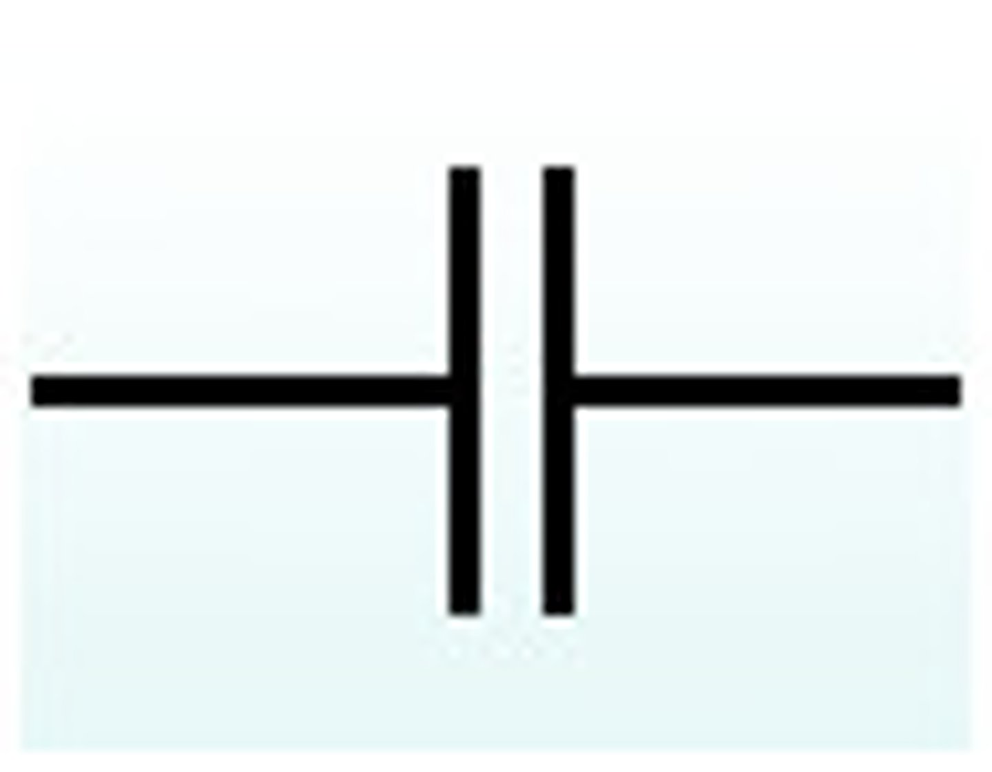
Circuit symbol for parallel plate capacitor
Here

Capacitors store capacitance, which is defined as
The charge stored per unit potential.
(Or ratio of charge on an object to its potential)
Greater capacitance =
Greater charge stored on capacitor
2 forms capacitors come in
isolated spherical conductors, parallel plate capacitors
Isolated spherical conductors
- stores charge on its surface
- as p.d. of supply increases, the charge of the conductor also increases
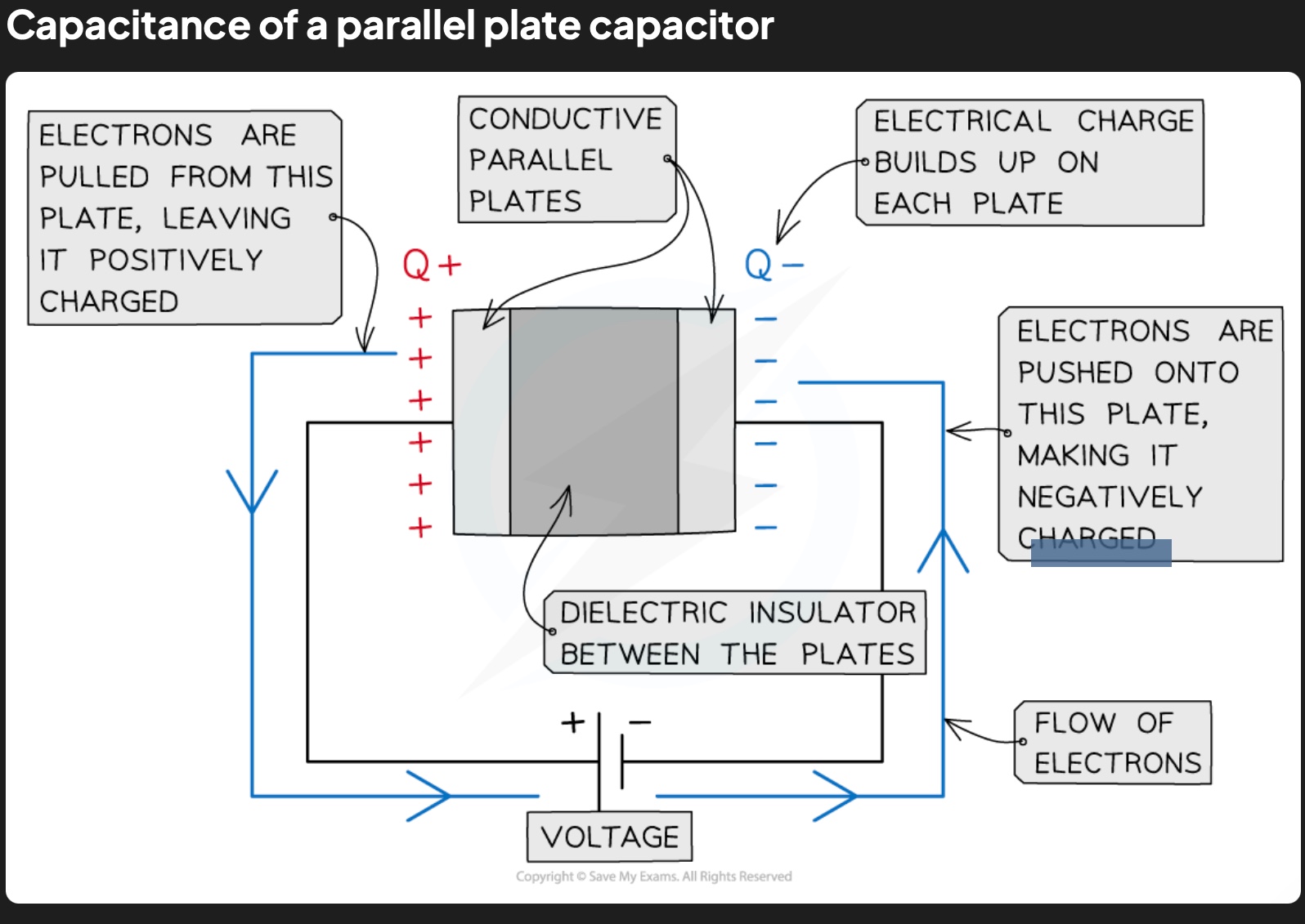
Parallel plates capacitors
- made up of two conducting metal plates connected to a voltage supply
- negative terminal of voltage supply pushes electrons onto one plate, making it negatively charged
- electrons repelled from opposite plate, making it positively charged
- there’s a (dielecteric) insulator between the plates which ensures charge doesn’t flow freely between the plates
charge stored by capacitor refers to
magnitude of charge stored on each plate in a parallel plate capacitor/surface of a spherical conductor
capacitor itself doesn’t store charge
capacitance formula
C = Q / V
C = capacitance (F)
Q = charge (C) … on plates
V = potential difference (V) … across capacitor
unit of capacitance
Farad (F) = 1 Coulomb per Volt, 1 C V-1
capacitance of a spherical conductor
charge per unit potential at surface of the sphere
because charge on surface of a spherical conductor can be considered as a point charge at its centre
Q= charge stored on surface of spherical conductor (not charge of capacitor)
V of an isolated point charge =
V = Q/ (4πε0R)
and C=Q/V so V=Q/C
so V=Q/C = V = Q/ (4πε0R)
so C= 4πε0R
combined capacitance of capacitors in a circuit depends on…
whether they’re connected in series or parallel
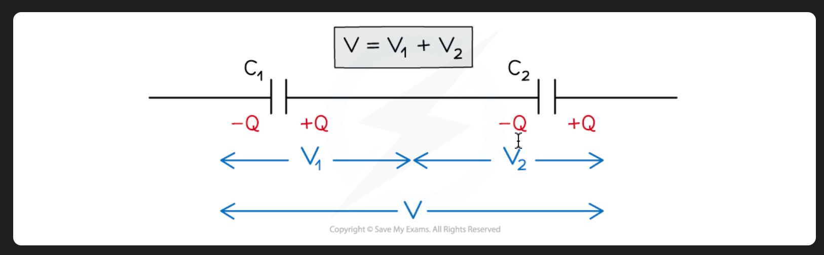
derive formulae for capacitance of capacitors in series
consider 2 parallel plates capacitors C1 and C2 connected in series with a p.d. V across them
in a series circuit, p.d. is shared between all the components in the circuit
therefore, if capacitors store same charge but diff. p.d.s, the p.d. across C1 is V1 and across C2 is V2
total p.d. V = sum of V1 and V2
V = V1 + V2
∴ V1 = Q/C1 and V2 = Q/C2
total p.d. => V = Q/Ctotal
substitute into V = V1 + V2
Q/Ctotal = Q/C1 + Q/C2
since current is same throughout all components in a series circuit, charge is same through each capacitor and cancels out
∴ eqn. for combined capacitance in a series circuit
1/Ctotal = 1/C1 + 1/C2 + 1/C3 + …
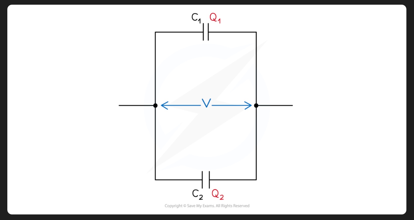
capacitors in parallel
since current is split across each junction in a parallel circuit, the charge stored on each capacitor is different
therefore charge on capacitor C1 is Q1 and on C2 is Q2
total charge Q:
Qtotal = Q1 + Q2
therefore (by rearranging capacitance eqn.)
Q1=C1V and Q2=C2V
total charge Q is defined by total capacitance
Qtotal = CtotalV
substitute in Qtotal = Q1 + Q2
CtotalV = C1V + C2V
since p.d. is same across all components in a parallel circuit, p.d. V cancels out
∴ combined capacitance of capacitors in parallel
Ctotal = C1 + C2 + C3 +…
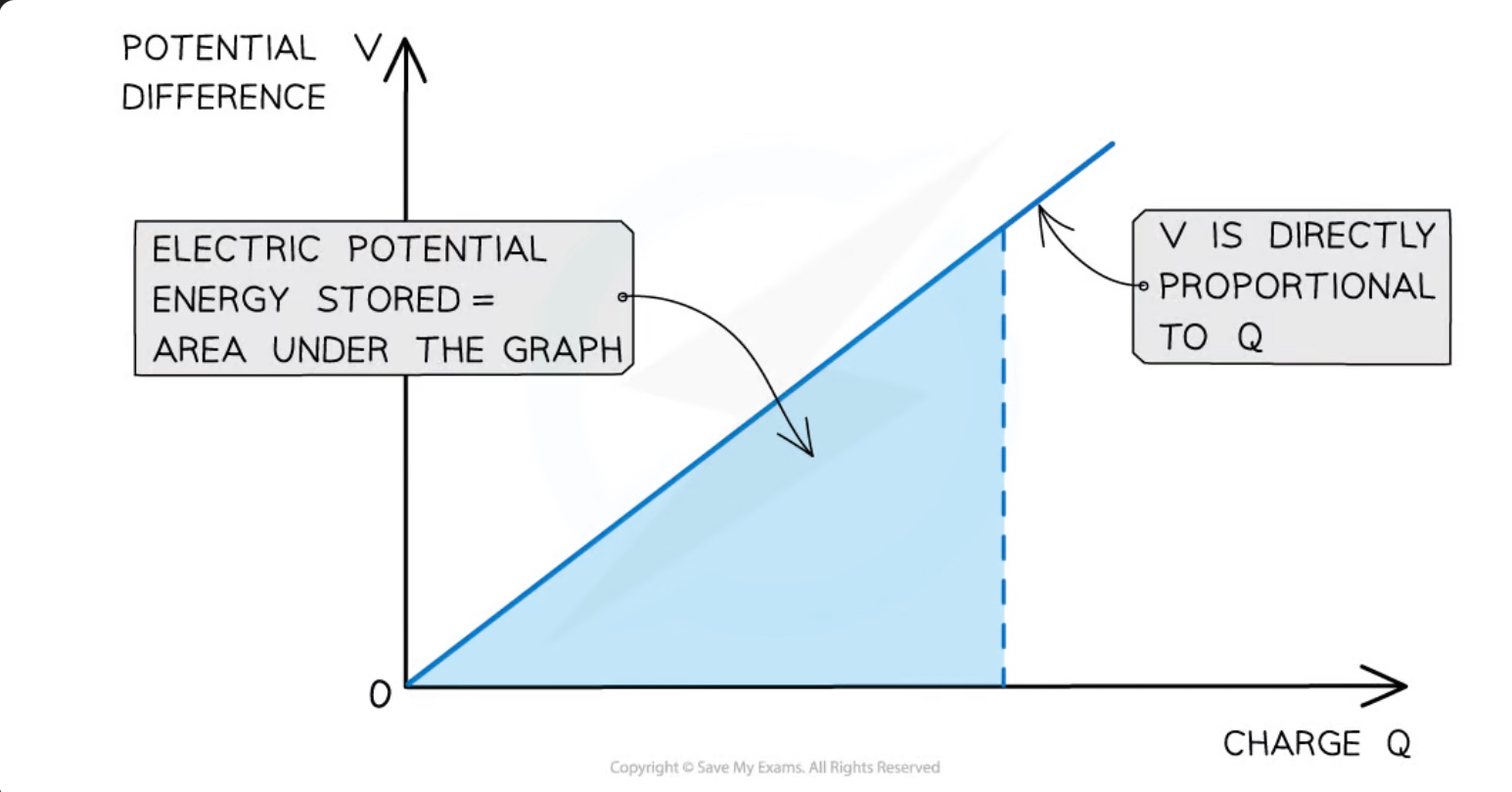
determine the electrical potential energy stored in a capacitor from a potential charge-graph
electrical potential energy stored in a capacitor = area under potential-charge graph
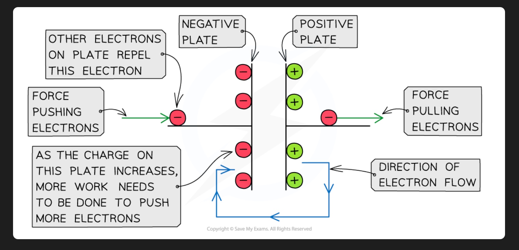
how electrical potential energy is produced on a capacitor
when charging a capacitor, power supply transfers electrons on one plate, giving it a negative charge, and transfers electrons away from the other plate, giving it a positive charge
∴ it does work on the electrons, which increases their electrical potential energy
as charge of negative plate increases, the electric repulsion between electrons increases
thus greater amount of work needs to be done to increase the charge on the negative plate
also, charge Q on the capacitor is directly proportional to its p.d. V, so the graph is a straight line passing through the origin
energy stored in a capacitor formula
electrical potential energy is equal to the area under a potential-charge graph
this is equal to the work done in charging the capacitor across a particular p.d.
∴ the work done/energy stored in a capacitor is defined by
W = ½ QV
substitute charge as C = Q/V ∴ Q=VC
∴ W = ½ CV2
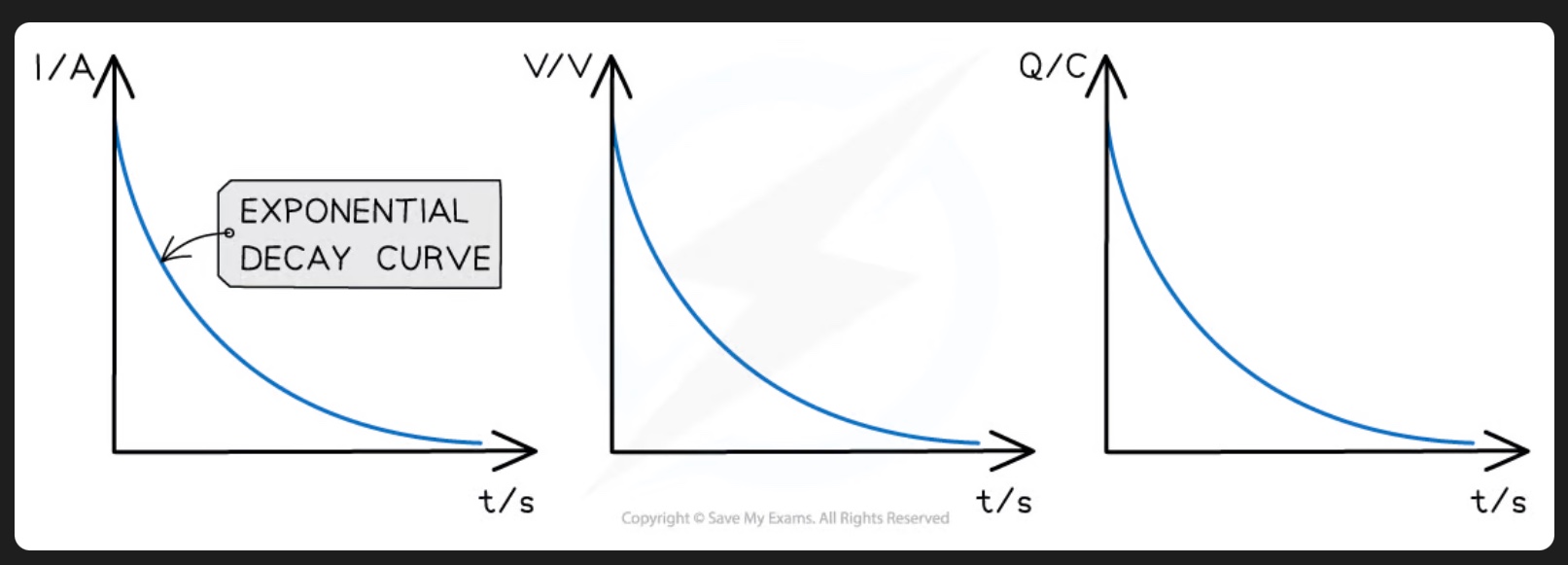
capacitor discharge graphs
capacitors are discharged through a resistor
electrons flow from negative plate to positive plate until there are equal numbers on each plate
as capacitor discharges, the current, p.d. and charge all decrease exponentially
so these graphs w.r.t. to time are all identical and represent exponential decay
the rate at which a capacitor discharges depends upon…
the resistance of the circuit
high resistance = current decreases = charge flows from capacitor plates more slowly = more time for capacitor to discharge
& vice versa
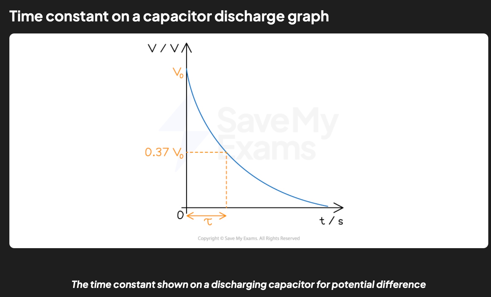
time constant, (𝜏), of a capacitor discharging through a resistor
a measure of how long it takes for the capacitor to discharge
defined as: the time taken for the charge, current or voltage of a discharging capacitor to decrease to 37% of its original value
unit seconds
time constant 𝜏 equation
𝜏 = RC
𝜏 = time constant (s)
R = resistance of resistor (Ω)
C = capacitance of capacitor (F)
find time constant from graph
find 0.37V0 and the corresponding time for that value = time constant
capacitor discharge equation
x = x0e-(t/RC)
x = current, charge or p.d.
x0 = initial current, charge or p.d. before discharge
e = the exponential function
t = current time/time elapsed
RC = resistance (Ω) * capacitance (C) = time constant (𝜏)
equation shows that greater time constant… and greater initial current…
greater time constant = greater the speed at which current/charge/p.d. falls during discharge
greater initial current/charge/p.d. = greater rate of discharge (capacitor will take longer to discharge)