ARU QUIZ
1/72
There's no tags or description
Looks like no tags are added yet.
Name | Mastery | Learn | Test | Matching | Spaced |
|---|
No study sessions yet.
73 Terms
ELECTRICAL MEASURING INSTRUMENTS
are instruments that use the mechanical movement of electromagnetic meter to measure voltage, power, current.
TWO TYPES OF ELECTRICAL MEASURING INSTRUMENT
Analog type
Digital type
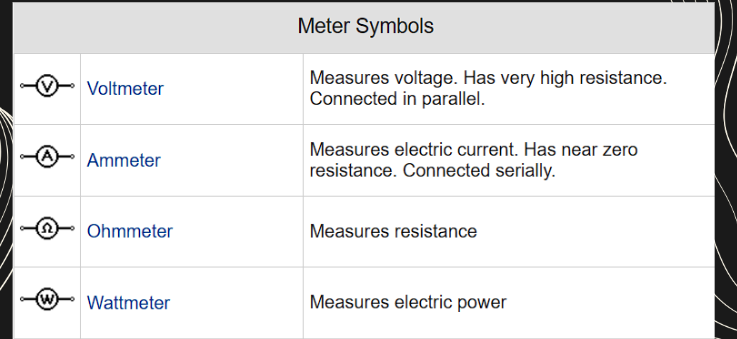
Ammeter
a instrument to measure the current in a circuit
Voltmeter
measuring is used for electrical potential difference between two points
Clamp meter
electrical test tool that combines a basic digital multi meter
Multimeter
knows as VOM, electrical measuring instrument that combines several measurement functions
Megger
measuring the resistance of the insulation
Continuity Tester
to determine if an electrical path can be established between two points
tachometer
an instrument measuring the rotation speed of a shaft or
disk, as in a motor or other machine.
watt hour meter
watt meter
an instrument for measuring the electric
power in watts of any given circuit.
Frequency meter
an instrument that displays frequency of a periodic electrical signal
power factor meter
r measures the power factor of a
transmission system. The power factor is the cosine of the
Angle between the voltage and current.
ohmmeter
an instrument used to measure resistance
electrical plan?
a drawn description of a building’s
circuit and electrical properties.
contents of an electrical plan
Cable routing diagram - the positioning of the electrical cabinets, cable
types and their routes, the positioning of every electrical equipment and
device in the building.Electrical distribution wiring diagram - devices in the electrical cabinet and
their wiring.Quotation - device price and items list, service fee, item number.
Bill of material
Technical description
Topological drawing - the form taken by the network of interconnections of
the circuit components.
types of Electrical plan
residential
commercial
industrial
institutional
mixed use development
hospitality
Landscaping
emergency services
Components
of an
Electrical
Plan
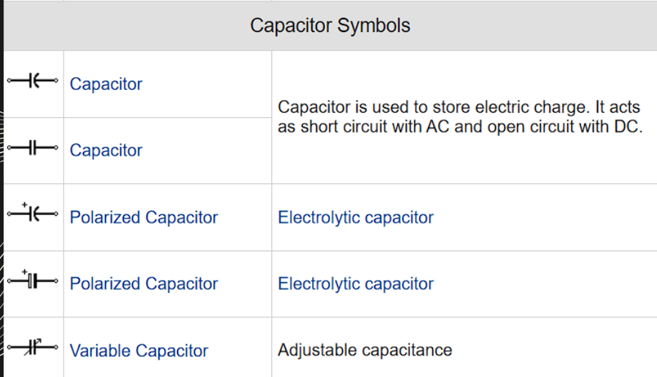
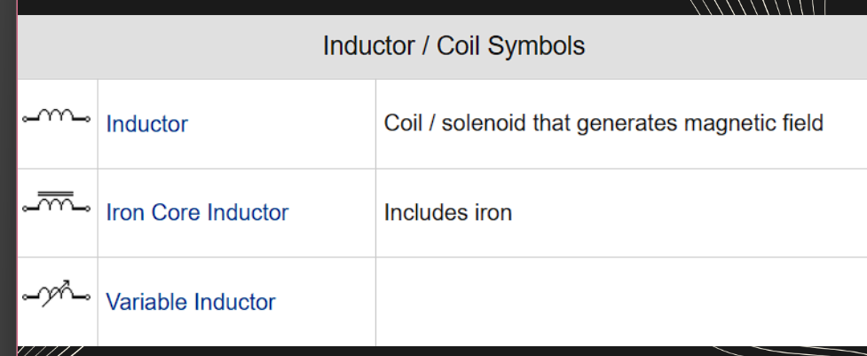
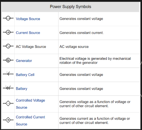
LEGEND
POWER PLAN
LIGHTING PLAN
CIRCUITING
PANEL SCHEDULE
SINGLE LINE DIAGRAM
EQUIPMENT LAYOUT
SPECIAL SYSTEMS
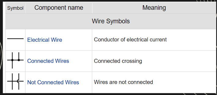
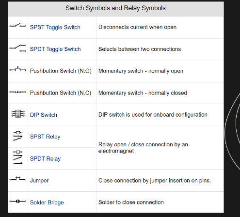
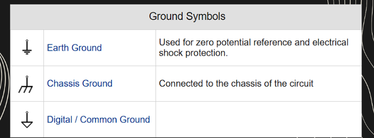
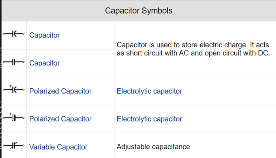
LEGEND
key part of
the electrical plan,
explaining the symbols used
in the drawing. These
symbols represent various
electrical components such
as outlets, switches, lights,
and wiring.
POWER PLAN
hows the layout of all power
outlets and electrical appliances. It includes
details about the types of outlets (e.g.,
standard, GFCI) and their locations.
LIGHTING PLAN
indicates the placement
of light fixtures, switches, and control
points. It ensures proper illumination
levels for different areas of the building
CIRCUITING
shows how different electrical devices
are connected and grouped into circuits.
PANEL SCHEDULE
lists the electrical circuits
and their corresponding circuit breakers within
the distribution panel.
SINGLE LINE DIAGRAM
is a simplified
representation of the electrical distribution
system. It shows the main components like
transformers, distribution panels, and main
circuit breakers.
EQUIPMENT LAYOUT
This part of the plan details the positioning of
major electrical equipment such as
transformers, switchboards, and generators.
SPECIAL SYSTEMS
refer to additional electrical
systems like fire alarms, security systems, and
data networks. These are integrated into the
overall electrical plan.
elements of an electrical plan
Wiring Diagrams
Circuit Layouts
Lighting sytems
Lighting systems
Power distribution
Wiring Diagrams
Essential for illustrating the physical connections and layout
of the electrical circuitry.
Circuit Layouts
It detail the specific circuits within the
electrical system.
Lighting Systems
A significant part of any electrical plan. They include the
placement of light fixtures, switches, and outlets.
Power Distribution
Outlines how electricity is
delivered from the main power
source to various parts of the
building.
ELECTRICAL LOAD
an electrical component or portion of a
circuit that consumes (active) electric power, such as
electrical appliances and lights inside the home. The term
may also refer to the power consumed by a circuit.
TO SOLVE FOR THE
ELECTRICAL LOAD?
Load(W) = Voltage(V) x Current(A)
Single-Phase current calculation:
I = P ÷(V× PF)
Three-phase current calculation:
I = P÷ √3 V × P.
Safety Standards: NEC
(National Electrical Code)
Compliance with electrical codes and
standards to ensure safe and reliable
operation
Energy Efficiency:
Sustainable Practices
Design of energy-efficient systems to
reduce energy consumption and
environmental impact
Building management systems (BMS)
referred to by several different names, including
“building automation systems (BAS),” “building control
systems,” and even “smart buildings”.
types of building management system
HVAC Control
Lighting Control
Security and Access Control
EMS
BMCS
Fire Alarm and Safety Sytem
Heating, Ventilation, and Air Conditioning
(HVAC) control system
is a computerized
mechanism that adjusts the heating, air
conditioning, and ventilation components within a
building
Self-contained unit packages
It describes a single unit
that converts a primary energy source (electricity or gas)
and provides final heating and cooling to the space to be
conditioned. Rooftop HVAC systems, air conditioning
units for rooms, and air-to-air heat pumps are included in
it.
Central systems
hese are a combination of central
supply subsystems and multiple end-use subsystems. With
central systems, the main conversion from fuel such as gas
or electricity takes place in a central location. Some form
of thermal energy is distributed throughout the building or
facility.
Lighting automation systems
as smart
lighting systems, are designed to control and monitor the
lighting in a space
benefits of homes lighting control
1. Be more energy efficient
2. Programmed scene setting
3. Improve the safety and security of your home
4. Enhanced convenience
5. Increase light usage
EMS An energy management system (EMS
a set of tools combining software and hardware that optimally
distributes energy flows between connected distributed energy resources (DERs). Companies use
energy management systems to optimize the generation, storage and/or consumption of electricity to
lower both costs and emissions and stabilize the power grid.
Common components of an energy management system
Gateway: a data collection and processing system that ideally operates independently of
manufacturers.Software: a range of sophisticated algorithms that create rules and restrictions to control energy
assets according to specific needs e.g. to maximize self-sufficiency, charge devices in order of
preference or to set limits for energy consumption according to local grid requirements.Interface: a platform that enables users to visualize live and historical data, view KPIs, set
parameters, and manage energy flows.
A building management and control system (BMCS)
ontrols and monitors the internal environmental conditions of
commercial buildings
Levels of BMCS
FIELD LEVEL
The field level refers to
application specific
controllers, such as terminal
devices including fan coil
units, and variable air
volume boxes and control
peripherals, such as sensors
and valve or damper
actuators.
SYSTEM LEVEL
The system level, also
known as the automation
level, is associated with
controllers serving the main
plant such as the air
handling units, chillers and
boiler control.
MANAGEMENT LEVEL
The management level
comprises the BMCS server
and the operator workstation,
also known as the head end or
building dashboard. The
management level of control
allows the management and
monitoring of the control
system from a single point.
ENTERPRISE LEVEL
In some installations there is a
fourth level, the enterprise
level. This sits above the other
levels usually within a
corporate network to provide
data analysis such as asset
management.
Security automation system
a form of computer-based
security technology that automates identifying, monitoring,
and responding to threats to an organization’s digital
infrastructure.
Fire Alarm and Safety System
designed to detect the outbreak of
fires and provide warnings, for example by sounding alarm
bells throughout the building
Communication system
a comprehensive framework that facilitates the exchange of information between two or more entities
telephone
involves
transmitting voice over telephone lines,
primarily for real-time interaction
PARTS OF TELEPHONE
Microphone: Captures voice.
Speaker: Reproduces voice.
Dial Pad: Initiates calls.
Ringer: Alerts for incoming calls.
ADVANTAGES of telephone
Immediate Response: Enables quick, interactive
communication.Long-Distance Capability: More effective and less
expensive than physical travel.Personalized Communication: Allows emotional
expression through tone, reducing misinterpretation.Confidentiality: Better suited for sensitive information,
ensuring messages reach the intended recipient.Safety: Bluetooth technology allows safer use while
driving compared to texting.Business Aid: Essential for marketing, customer service,
and communication in service industries like
restaurants and hotels.Flexibility and Affordability: Mobile phones enhance
communication through internet access and various
platforms.
INTERCOM
is a standalone system for
voice and video communication within a building or small group of
buildings. It enables two-way communication, allowing a person to speak
into a microphone and be heard elsewhere.
PARTS OF INTERCOM
Microphone: Captures voice.
Speaker: Reproduces sound.
Control Unit: Manages communication between
components.Push Buttons: Initiate communication or unlock
doors.Camera: Captures video for visual communication
(in video intercoms).Monitor: Displays the video feed from the camera.
Power Supply: Provides necessary power for
operation.Wiring: Connects components in wired systems.
Antenna: Enables wireless communication in
wireless systems.Gateway: Connects smart intercoms to the
internet for remote access.
CABLE TV
This form of transmission
shared TV signals. Cable systems were originally
built to extend the reach of TV signals and improve
over-the-air TV reception. Modern cable systems
use fiber and coaxial cable for signal transmission.
AUDIO VISUAL
COMMUNICATION
is a productive
form of communication. Using sound and lighting
equipment improves communication by
heightening the awareness of your audience's
sight and hearing.
Video
Communication
has significantly
increased in the business sector, facilitating
connections among employees worldwide
and enhancing collaboration, performance,
and growth.
Types of Video Communication:
Video calling
Video conferencing
Telerpresence
Video sharing
Public Address (PA) System
is an
electronic sound amplification and
distribution system with a microphone,
amplifier and loudspeaker. *
Block diagram of PA System
Components:
Microphone: Converts sound waves into electrical signals.
Mixer: Isolates different audio channels before amplification.
Voltage Amplifier: Further amplifies the mixer output.
Driver Amplifier: Reduces internal resistance for the next stage.
Power Amplifier: Provides significant power amplification to the signal.
Loudspeaker: Converts electrical signals into sound.
Typical PA installation Planning
I. Public meeting
II. Auditorium having large capacity
III. Debating chamber
IV. Football stadium
V. College sports
Application of PA SYSTEM
Sports meets
Public meeting
Auditoriums
Concerts & functions
Railway station
Airports
Hospitals
Factories
