Gas Detectors and GM Meters
1/41
Earn XP
Description and Tags
Nuclear Medicine Instrumentation
Name | Mastery | Learn | Test | Matching | Spaced |
|---|
No study sessions yet.
42 Terms
More Radiation =
More Ion Pairs
Less Radiation =
Less Ion Pairs
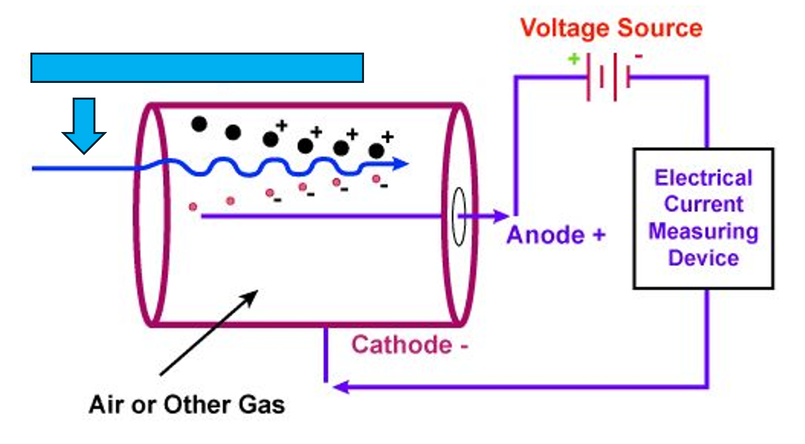
Incident Ionizing Radiation
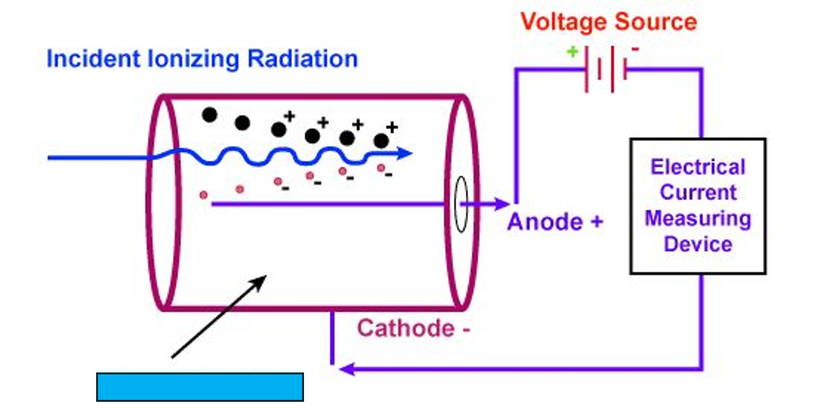
Air or Other Gas
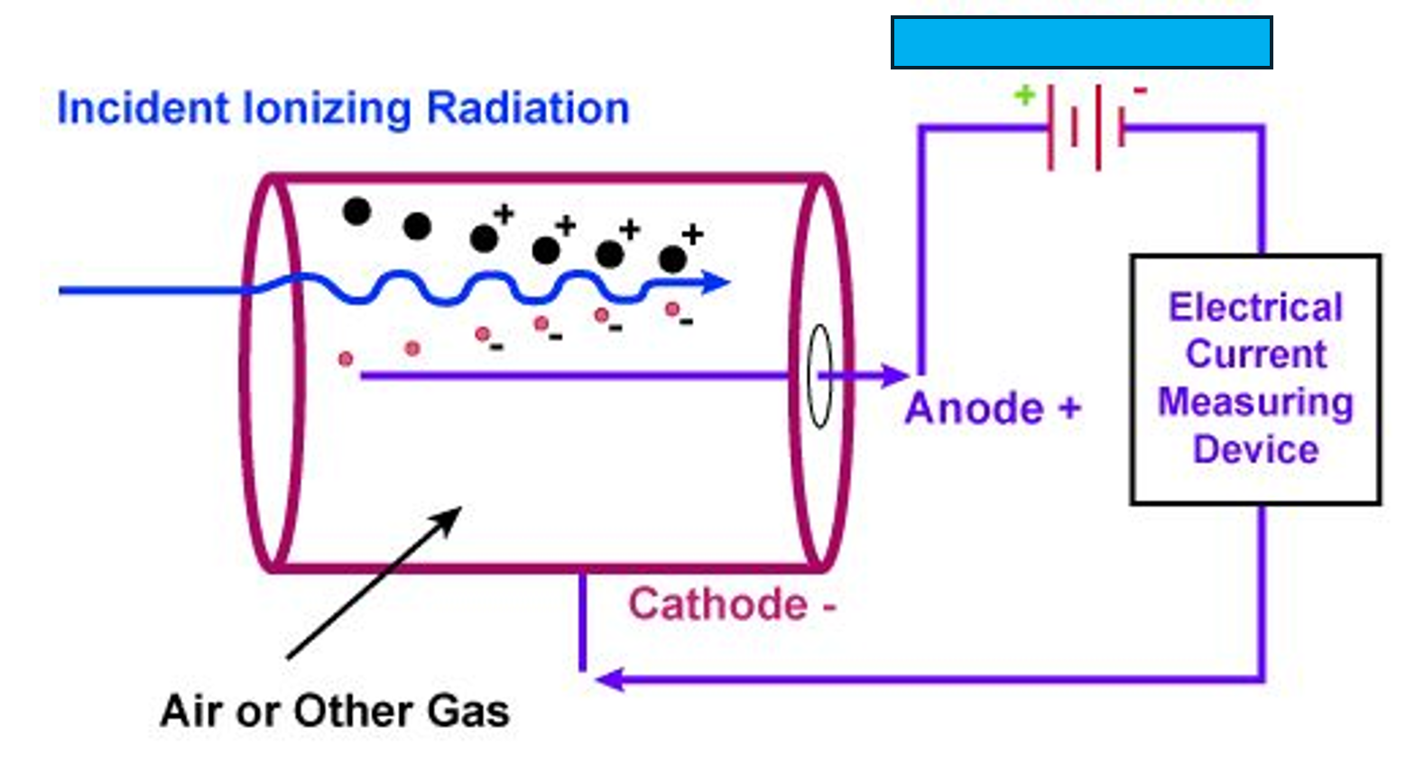
Voltage Source
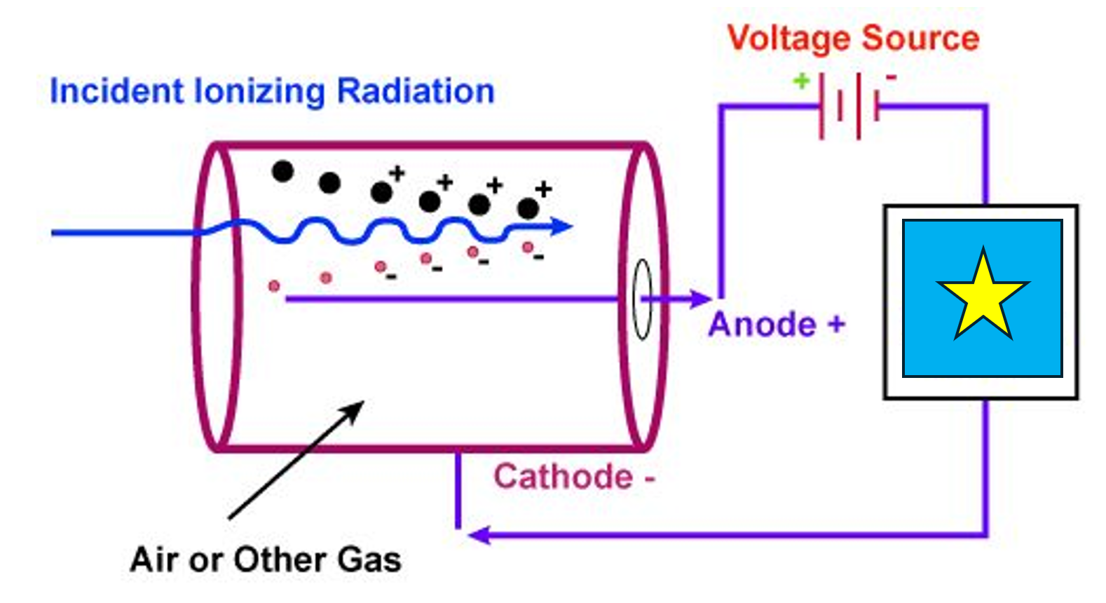
Electrical Current Measuring Device
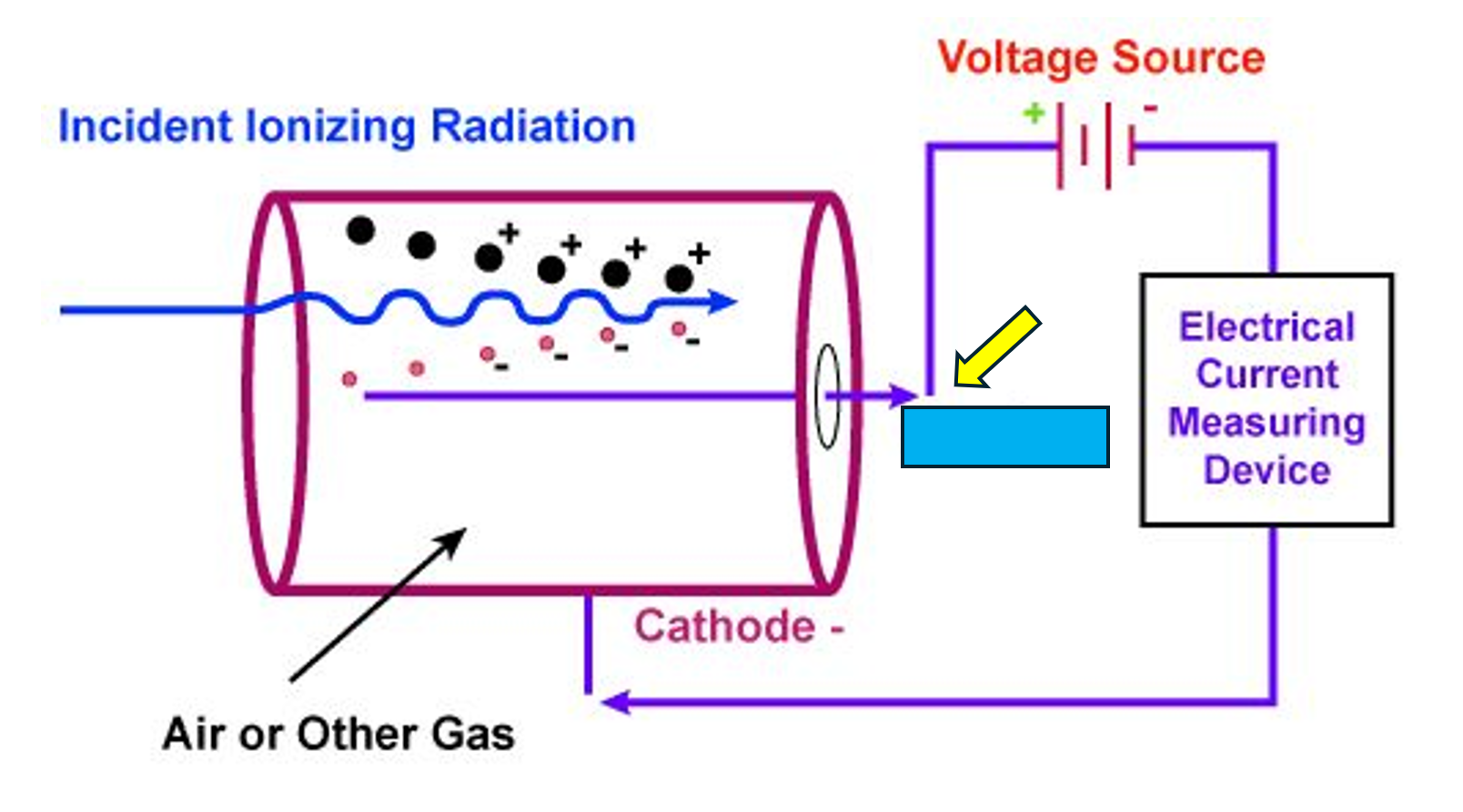
Anode +
Cathode -
Ion Pairs
Created when radiation interacts with atoms and molecules
Need a small amount of radiation
# of Electrons created is
related to the amount of radiation/radioactivity present
Gas Detectors
Simplest radiation detectors
❖ Ion Pairs are created in the chamber filled with gas
❖ Have 2 basic parts:
❖ Chamber Filled with Gas
❖ Basic Electric Current
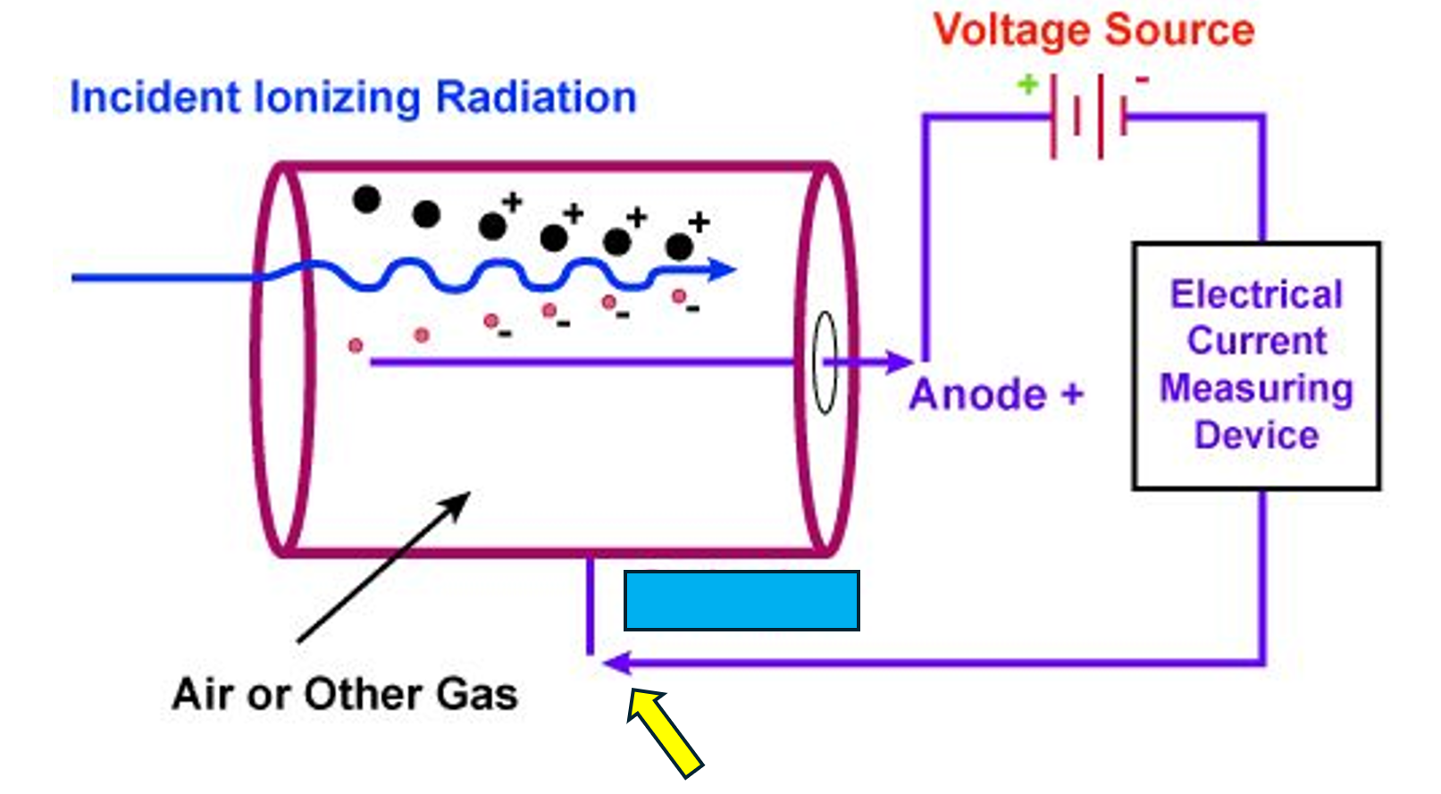
Anode
Has a + charged central wire that attracts electrons produced by ion pairs during radiation detection.
Cathode
Has a - charged metal tube that helps to collect electrons produced during ionization in gas detectors.
Power Source
Keeps the cathode and anode charged with
positive or negative charge from the power source
Electrical Current Measuring Device
Meter that is attached to the power source measures
the flow of electricity that occurs as a result of the
neutralization of charge at the anode and cathode
Gas Detector Operation
Remove the radiation source
❖ The gas between cathode and anode act as an insulator
ADD Radiation
❖ Energy over 10 electron volts (eV) passes through gas
and ionizes gas molecules, producing free electrons and
positive ions
❖ Average energy required to cause ionization is between
20-45 eV
Electrons move faster + ions
❖ Electrons collect at anode
❖ These electrons can neutralize some of the + charge
❖ Causing electricity to flow through the connecting circuit
# of electrons measured depends on
❖ # of charged particles/photons being measured
❖ Energy of the radiation
❖ Geometric Configuration of the detector
❖ Composition of gas in the chamber
❖ Applied voltage between cathode and anode
Voltage Response Curve
The curve representing the applied voltage between the cathode and anode.
There are 6 regions
Recombination Region
❖ Applied Voltage very LOW
❖ Electrons moving very slowly and do NOT reach the anode and cathode
❖ Incomplete collection of ions
NO useable detectors that operate in this region!!
Ionization Region
❖ AKA Saturation Region
❖ Applied voltage increased
❖ All electrons are being collected
❖ Saturation voltage is voltage sufficient enough to reach the saturation point
❖ Wide flat range, where even if voltage fluctuates, the same # of electrons will be collected
Useful for Radiation Detection
Proportional Region
❖ Electrons from radiation interactions are easily accelerated by higher voltages to create additional ionizations with collisions of gas molecules
❖ Gas Application
❖ Applied voltage creates signal that is larger than BUT still proportional to the # of ion pairs
NOT COMMONLY USED IN NUCLEAR MEDICINE
Limited Proportionality Region
❖ Ions are larger than electrons
❖ Drift slowly toward cathode
❖ Voltage response curve no longer changes linearly with increasing voltage
NOT USEFUL FOR RADIATION DETECTION
Geiger-Muller Region
❖ AKA-GM Region
❖ At high voltages, gas amplification effect is maximized
❖ Each electron creates many ionizations
❖ Each radiation event produces an avalanche of ions through the chamber
❖ Pulse size is essentially the same for ALL radiation events
❖ No matter the type or amount of energy transferred
GM Meters work here!!
GM Meters are a workhorse in the NM Department
Continuous Discharge Region
❖ Increase voltage above GM region
❖ Causes spontaneous ionizations in the detector without radiation present
NO USEFUL RADIATION DETECTORS HERE
Current Mode
❖ Measures the number of electrons per second required to keep the anode and cathode charged
❖ Detectors that operate in current mode are connected to a power supply that strives keep the anode and cathode fully charged
❖ Measurement is based on the time-average # of ionizations occurring per second
Ion Chambers and Dose Calibrators Operate Here
Pulse Mode
❖ Electrons created by each radiation interactions are treated as a group
❖ Pulse created as a single entity
❖ Restoring electrical potential between anode and cathode measured as a single entity
❖ Size of pulses represents total change deposited by a single radiation interaction
❖ Dead time affects the counting ability in pulse mode
GM Meters Operate Here
Ion Chambers/ Exposure Rate Meters
Gas Filled Detectors
Used to measure exposure rate and to determine the relative amount of penetrating and non penetrating radiation
Uses Current Mode
Works in Ionization Region
Read in mR/hr, reads accurately down to 1mR/hr
NOT appropriate to use for detecting radiation contamination
Gases Used In Ion Chambers/ Exposure Rate Meters
Helium
Neon
Argon
Geiger-Mueller (GM) Detector
One of the workhorse’s of the NM department
Operates in the Geiger Mueller Region
Operates in Pulse Mode
Used as a qualitative indicator of radiation
Excellent for finding contamination
Highly reliable and stable
Can read in mR/hr of cpm (counts per minute)
Types of Geiger-Mueller Detector Probes and Meters
End Window
Side Window (energy compensated)
Pancake
GM Meter Quality Control Checks
Accuracy Check or Calibration
Daily
Accuracy Check or Calibration QC
Performed Annually
Sent out for Calibration and Accuracy
Daily QC
Battery Check
Constancy
Voltage
When To Use A Geiger-Mueller Detector
Monitoring radioactive packages coming and leaving the department
Check for contamination on yourself or in a room
End of the day room checks
Geiger-Mueller Detector Pitfalls in Inaccurate Readings
Math Error
User Error
Reading Wrong Scale
Multiplication Error
Factors Affecting Observed Exposure or
Count Rate – Dead Time
Instrument design to handle dead time
Paralyzable vs. Non-paralyzable
Dead Time
The detector has a limited time it takes to process and record an event
Paralyzable
Event happening during dead time will be missed, but the dead time restarts
Instrument reaches saturation point and unable to record and further events
Non-Paralyzable
Event happening during dead time is lost
With increasing event rate the detector will reach a saturation rate equal to the inverse of the dead time
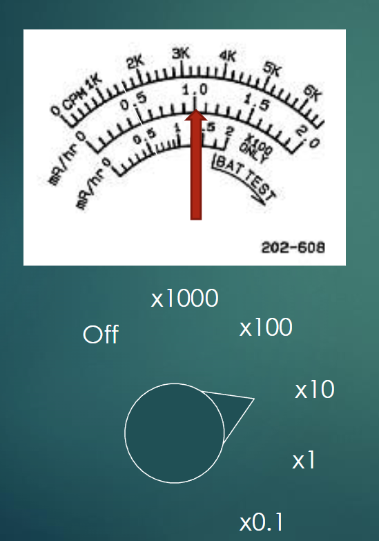
What Exposure Rate is Displayed
Meter is set to x10 and the arrow is pointing to 1.0
1.0 × 10 = 10 mR/hr
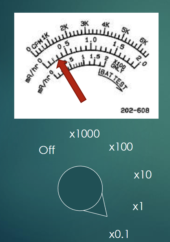
What Exposure Rate is Displayed
Meter is set to x0.1 and the arrow is pointing to 0.3
0.3 × 0.1 = 0.03 mR/hr
What Exposure Rate is Displayed
Meter is set to x100 and the arrow is pointing to 0.6
0.6 × 100 = 60 mR/hr