Image Formation Pulse Sequences
1/96
There's no tags or description
Looks like no tags are added yet.
Name | Mastery | Learn | Test | Matching | Spaced |
|---|
No study sessions yet.
97 Terms
pulse sequence
set of specifically timed instructions to the magnet telling it how images should look with regards to the tissue being sampled
Gradient echo
gradient echo sequence lacks _______ making it more susceptible to __________
180° refocusing RF pulse, magnetic field inhomogeneities.
why are Gre sequences fast
the lack of 180° refocusing pulses, the TR can be shorter, thus shortening scan time
In a gradient echo pulse sequence, the gradient coils are used to
refocus the protons and create the echo.
In order to produce an echo in a gradient echo pulse sequence,
a gradient field and an RF pulse are used.
Gradient echo sequences can yield ________ with influences caused by
either T1 or T2* characteristics, susceptibility, chemical shift, and inhomogeneities.
steady state occurs when
TR in a gradient echo is less than the T2 (or T2*), resulting in residual transverse magnetization at the time of the next excitation pulse
Gradient echo sequences requiring high signal from fluid
T2* gradient echo, steady-state gradient echo or coherent gradient echo
Gradient echo sequences requiring low signal from fluid
Incoherent gradient echo (or spoiled gradient echo) sequences
why do Incoherent gradient echo (or spoiled gradient echo) sequences give the contrast it does
removal of residual transverse magnetization before the next excitation
BTFE sequences are and are quipped with
variations of high T2 signal, balanced steady state sequences
equipped with slice, phase and frequency rewinder pulses, yielding images with mixed contrast T2/T1
BTFE sequences look like
image of high SNR with bright fluids, particularly useful in evaluation of cranial nerves
.
BTFE manufacturer names chart
Philips: BTFE
GE: Fiesta
Siemens: TrueFISP
Hitachi: BASG
Toshiba: True SSFP
spoiled gradient echo sequence does what
removes any residual transverse magnetization prior to the next excitation pulse
To reduce the steady state (T2*) effect what technique can be used
"spoiling"
"spoiling" technique does what
allow for fast scans with T1 contrast,
RF spoiling occurs when
additional RF pulses are used to "spoil away" the steady state effect (residual transverse magnetization) before the next excitation, yielding T1 contrast for dynamic imaging of organs or CE MRA sequences.
example of a T1 spoiled gradient echo sequence
SPGR Cor Oblique acquisition for a patient with history of seizures for evaluation of hippocampus
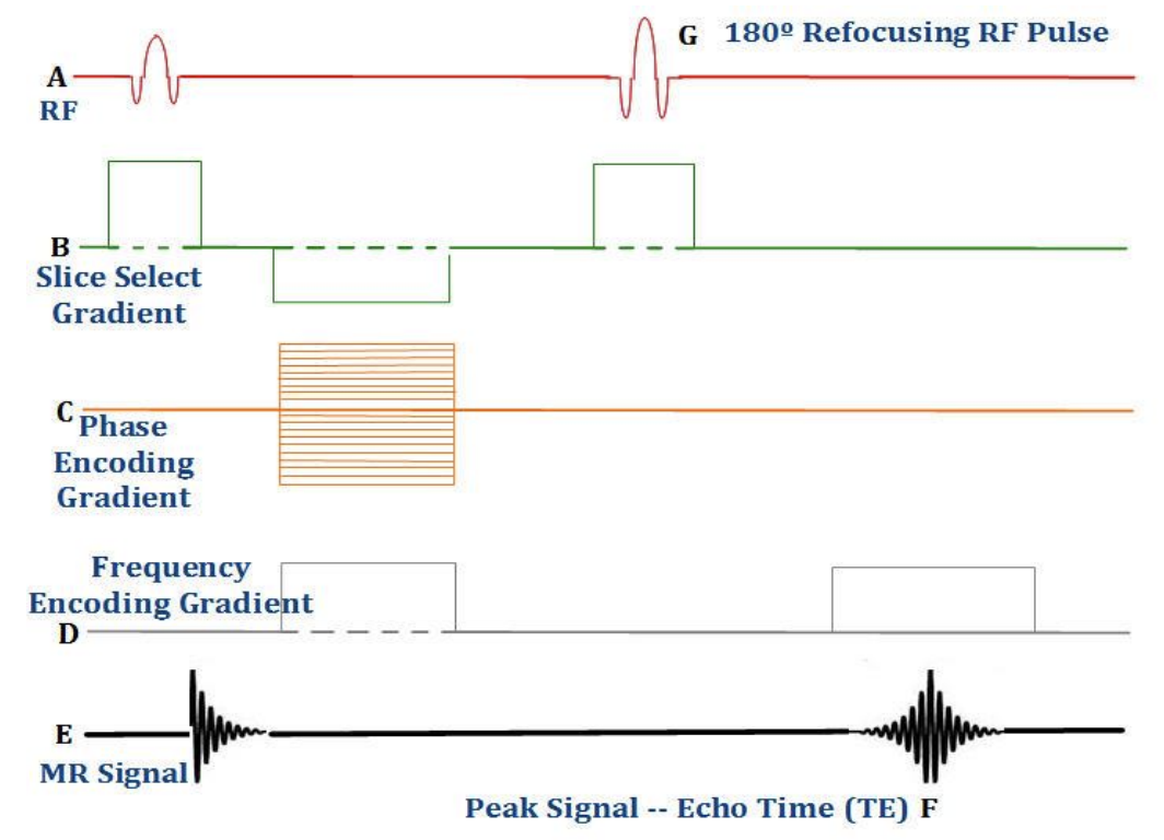
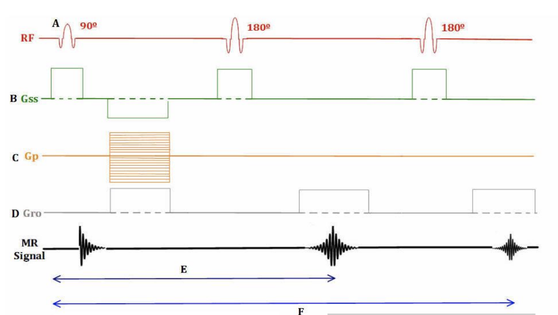
spin echo
Conventional spin echo sequences begin with
90° RF excitation pulse
what refocuses a decaying spin echo
The 180° RF pulse
Conventional spin echo techniques acquire ____ line(s) of k-space during each repetition (TR).
one
Fast spin echo techniques acquire ______ lines of kspace during each repetition.
multiple (2 to 50+)
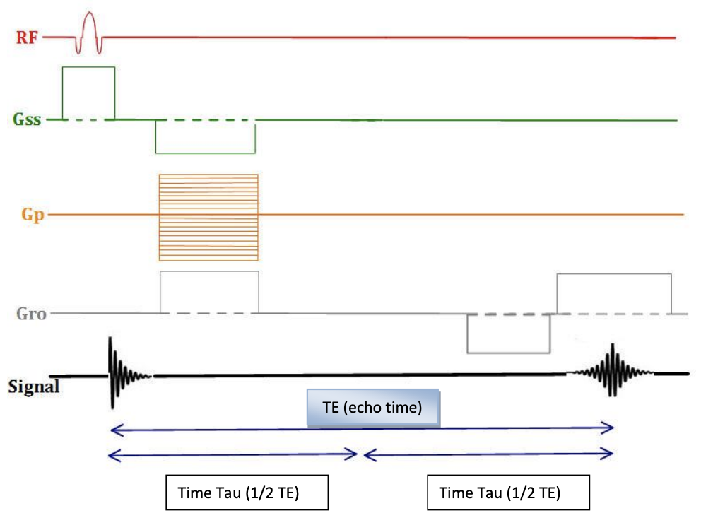
1/2 TE time (Tau)
In a spin echo sequence, the time between the 90° RF pulse and the 180° RF pulse
In a spin echo pulse sequence, an echo is produced from
a combination of two or more RF pulses
dual spin echo
In the pulse sequence diagram above, if there were 20 slices planned, 40 total slices would be reconstructed, with 2 slices per TE (TE1 and TE2) with differences in T2 weighting due to the differences in TE.
A dual echo spin echo sequence generates_____
two images for every slice,
in a dual spin echo with two images for every slice what are the characteristics
both have varying TE’s, but the same TR.
dual spin echoes generally acquired as
short TE (proton density weighted) and a long TE (T2 weighted) combination
Ex. In a dual contrast spin echo sequence with echo times of 25ms and 90ms, the second echo image has ______ contrast but ____ SNR than the first echo image.
more T2, lower SNR
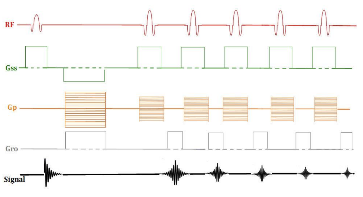
fast spin echo
in FSE Scan time is reduced by ___________ because
a factor matching the number of echo train lengths (TSE Factor--Philips), utilized,
several echoes for each slice are collected during each TR period.
Each train of echoes in a fast spin echo sequence _____ scan time _____ SNR and _____ SAR absorption in the patient.
reduces, lowers, increases
Conventional spin echo techniques acquire
one line of k-space during each repetition (TR).
Fast spin echo techniques acquire
multiple (2 to 50+) lines of kspace during each repetition.
In a fast spin echo pulse sequence, if the TSE factor (echo train length) is increased by a factor of 3
the scan time will be three times faster.
In a fast spin echo sequence, ____ are used to______, thus reducing scan time by the number of echoes.
multiple echoes, fill multiple lines of kspace for each TR period
In a Fast Spin Echo sequence, the effective TE are
the echoes that are encoded with a low amplitude phase encoding gradient
In a fast Spin Echo Sequence the effective TE occurs at
the line that is closest to the center of k-space (k0).
In a Fast Spin Echo sequence, increasing the # ETL can lead to
an increase in blurring.
in FSE the number of shots is calculated by
#Phase encodings / ETL
"shot" in a Fast Spin Echo pulse sequence
refers to the number of "nonredundant" RF excitations.
in a single shot sequence
the entire k-space matrix can be filled with a single excitation and a train of echoes matching the lines in k-space.
single shot sequence useful in
Abdominal MRI to reduce respiratory motion or to improve temporal resolution (speed)
In a Multi Shot sequence, ______ filled with each excitation, which can help
only a portion or fraction of the k-space data
increased spatial resolution (detail) opportunity
calculating the number of shots in a Fast Spin Echo sequence
Divide the # Phase Encodings by the Echo Train Length (ETL)
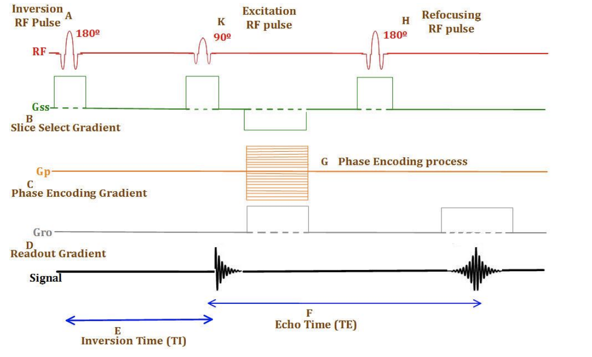
inversion recovery
inversion recovery
begins with a 180° RF pulse, followed by a 90° RF excitation pulse
IR first pulse designed to
null signal from fat or fluid, depending upon its length and proportional to field strength
TI (inversion time)
time interval between the 180° Inverting RF pulse and the 90° RF excitation pulse
types of inversion recovery sequences
STIR (short TI inversion recovery)
FLAIR (fluid attenuated inversion recovery)
3D-IR (T1 weighted inversion recovery)
If the desire is to null the signal from a specific tissue using an inversion recovery sequence, the inversion time (TI) selected should be
69% of the T1 relaxation time of that tissue
in a STIR sequence, the null point of fat in a 1.5Tesla magnet is
140-160 milliseconds
Short TAU inversion recovery (STIR) sequences are typically used for the evaluation of
compression fracture, lesions within retro-orbital fat, musculoskeletal contusions and fat suppression.
null the signal from fluid in a FLAIR sequence (CSF, for example) at 1.5Tesla, an Inversion Time (TI) of
2000ms would be used
T2 weighted FLAIR (fluid attenuated inversion recovery) sequences are typically used for evaluation of
periventricular white matter
SPGR stands for
SPoiled Gradient Recalled echo
SPoiled Gradient Recalled echo does what
the RF excitation pulse is phase shifted each time the RF is applied which prevents accumulation of the residual transverse magnetization effects throughout the acquisition, in effect, spoiling transverse magnetization
in SPGR if you combine iy with a short TE
reduce T2 effects and T1 effects will predominate the image contrast.
SPGR sequences by manufacturer
Siemens – FLASH (Fast Low Angle SHot , the original coined name for
the sequence upon development in 1985 in Germany)
GE – SPGR (SPoiled Gradient Recalled echo)
Philips – T1-FFE (Fast Field Echo)
Hitachi – SARGE (Steady state Acquisition Rewound Gradient Echo)
The repetition time (TR
is the time between two 90º RF excitation pulses
The echo time (TE)
he time between the 90º RF pulse and the peak of the signal in the receiver coil
Lengthening TR with a short TE in a spin echo sequence will
increase proton density weighting
As the TE is increased, the available number of slices is
decreased
longer TE means ______ slices can fit into the TR period
fewer
As the TR is increased, SNR is ____ and the available number of slices is ______
increased, increased
scan time in seconds
TR x Phase matrix x NEX = Scan time in milliseconds, ÷ 1000
scan time formula with ETL
TR x Matrix x NEX ÷ ETL
The timing of RF pulses in an MRI pulse sequence controls
image contrast.
Spin echo sequences contain _______, which _________, therefore making them the most _______ to inhomogeneity.
180° RF refocusing pulse(s)
which aid in correcting for local field inhomogeneities
insensitive
Reducing the flip angle yields images with less ________.
T1 information
The slice selection gradient is the determinant of
scan plane, slice thickness
using two ______ will create oblique scan plane
SSG
gradient that is on during the production of the echo
frequency encoding (readout) gradient
Echo-planar imaging capable of
acquiring an entire MR image in only a fraction of a second, and is the fastest sequence commonly available
fastest sequence commonly available
echo planar imaging
Spin echo pulses
90° RF followed by 180° RF
Fast spin echo pulses
90° RF followed by train of 180° RF pulses
Inversion recovery pulses
180° RF followed by 90°RF
Gradient echo pulses
~variable° RF followed by gradient to produce echo
A SE (spin echo) sequence can be best described as
a 90° pulse followed by a 180° pulse
A FSE (fast spin echo) sequence can be best described as
a "train" of spin echoes
An IR (inversion recovery) sequence can be best described as
a 180° pulse followed by a 90°/180° combination
An EPI (echo planar imaging) sequences can be best described as
a "train" of gradient echoes
450 TR; 30° flip angle combination would yield a
T2* weighted gradient echo.
45 TR; 90° flip angle combination would yield a
T1* weighted gradient echo.
Reducing the flip angle yields images with less
T1 information
Reducing the TE yields images with less
T2 information
Increasing the flip angle increases _____ up to
SNR, the Ernst angle.
what play a role in lengthening scan time in an MR pulse sequence
/\ TR
\/ the # ETL
/\ NEX
\/ the parallel imaging factor
what have an impact on shortening overall scan times in an MR pulse sequence
\/ TR
/\ the #ETL
\/ NEX,
enabling half-scan
/\ parallel imaging factor
what help to improve SNR in an MR image.
/\ TR
\/ the Phase Matrix
/\ the FOV
\/ (narrowing) the receive Bandwidth
/\ NEX/NSA
\/ the #ETL
what negatively impact SNR in an MR image
\/ in TR
\/ in Pixel Size
\/ in FOV
/\ (widening) of the receiver Bandwidth
\/ in NEX
/\ in #ETL