MECH2305 - Tolerances and Fits
1/42
There's no tags or description
Looks like no tags are added yet.
Name | Mastery | Learn | Test | Matching | Spaced |
|---|
No study sessions yet.
43 Terms
Tolerance
The exact limit allowed within the variation of the size for a component.
High vs Low tolerance
high tolerance costs more to produce, low tolerance parts may not function as expected.
Three methods of tolerance
Limits of size
Bilateral Tolerance
Unilateral tolerance
Limits of size
Upper and lower limit is specified.
Bilateral Tolerance
Basic size, and then add/subtract the same value.
Unilateral tolerance
Only one of the upper or lower limit is specified, with variation only allowed below or above this size.
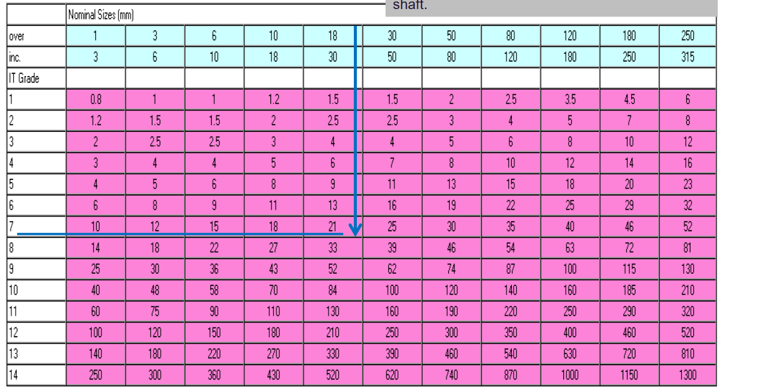
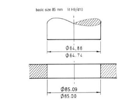
Using the table provided, find the tolerance for
Tolerance = +- 2×10^-6
Basic Size
The basic size, i.e. what it is in an ideal world.
Tolerance
Difference between max and minimum sizes.
Allowance
Difference between the mating parts.
Limits of size
The absolute maximum and minimum size possible.
Maximum/minimum material conditions
When external feature is at its upper/lowest limit, and internal is at its lowest/highest.
Fit
A fit between two parts is defined as the difference between their sizes before assembly.
3 Types of fits
Clearance fit
Interference fit
Transition fit
Clearance fit
There is always space between the shaft and the hole.
Interference fit
The shaft is always larger than the hole.
Transition fit
The shaft may be in either clearance or interference.
Hole basis system
Hole size is fixed and shaft size is varied to give different fits.
Shaft basis system
Shaft size is fixed and hole size is varied to give different fits
Geometric dimensioning and tolerancing
Worries about the shape, not the size of said shape.
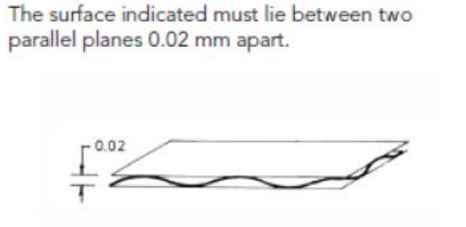
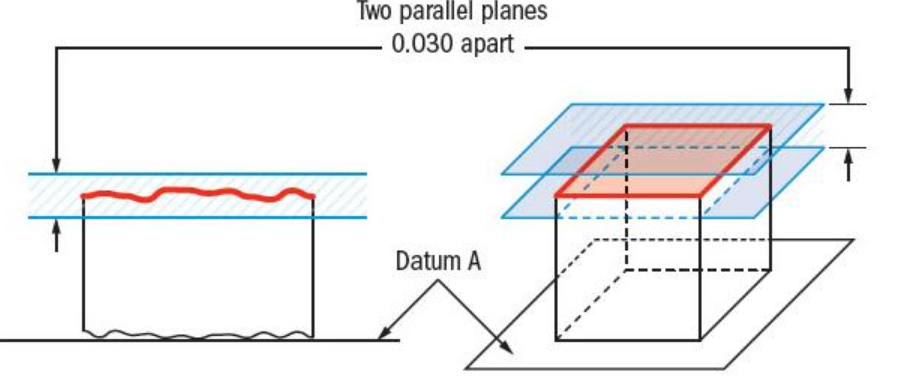
Flatness
Shape must fit between two parallel planes.
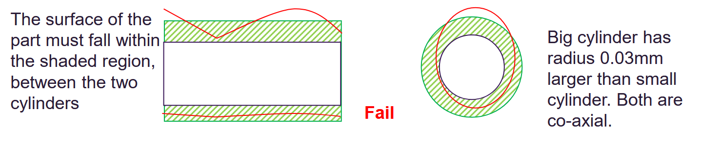
Cylindricity
Shape must fit between two cylinders, both the circles and lengthways
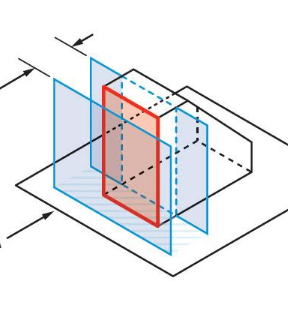
Perpendicularity
The shape must fit between two planes 90 degrees to the axis.
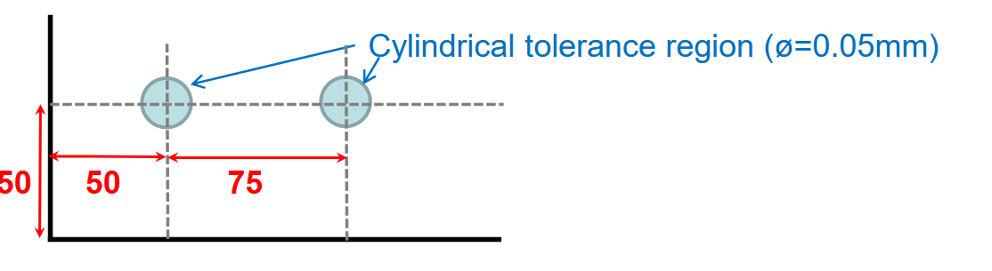
Position
Used to control location of a feature
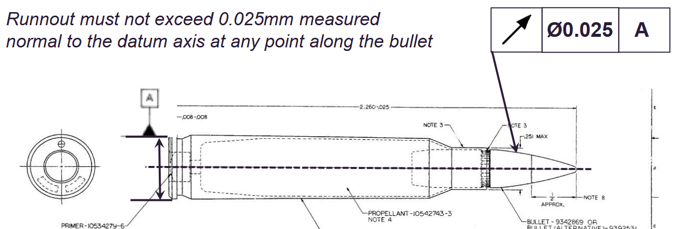
Run out tolerance
Very easy to apply, used to control location of circular part relative to its axis
Parallelism
Surface must be equidistant form planes at all times.
Flatness symbol
Parrellelogram

Cylindricity symbol
Circle between two sticks

Perpendicularity symbol
Two lines perpendicular

Position symbol
Circle with lines through middle

Concentricity symbol
Two circles around eachother

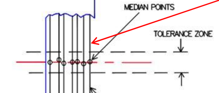
Concentricity
Used to establish a tolerance zone for median points
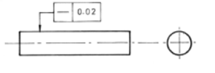
Run out tolerance symbol
Arrow

Parralellism symbol
two parrallel lines

Angularity
Must be between two perpendicular, bent planes.
Angularity symbol
A little angle

Straightness
Must fit within two straight lines
Straightness symbol
Flat, singular line


Maximum material condition
Tolerance only applies when feature is at its maximum size, i.e. if lower, tolerance can be increased to what the greatest would actually be.

Least material condition
Tolerance applies when at minimum size, i.e. if actual size is larger the minimum size, can go further below the tolerance.
Basic Surface Texture
The part may be produced by any method
Material removal by machinig is required
Machining must be applied to the surface to reach the desired surface quality
Material Removal Prohibited
No metal is to be removed, the surface is produced by casting, forging, hot or cold forming etc.