Chapter 5:Signals and Noise, Modern
1/31
There's no tags or description
Looks like no tags are added yet.
Name | Mastery | Learn | Test | Matching | Spaced |
|---|
No study sessions yet.
32 Terms
Signal
carries information about the analyte that is of interest to a scientist (observer)
Noise
is extraneous information, which degrades the accuracy and precision of analysis
- Places a lower limit on the amount of analyte that can be detected
- Random fluctuations in measurements that do not correspond to signal
Signal to Noise Ratior (S/N) is the Figure of Merit
𝐒/𝐍= 𝐦𝐞𝐚𝐧/𝐒𝐭𝐝. 𝐃𝐞𝐯.= x̄/𝐬= 𝟏/𝐑𝐒𝐃
S/N is the standard deviation of numerous measurements of the signal strength
We want to make the S/N as large as possible without impacting other criteria.
General Rule for S/N
It is impossible to detect a signal when S/N becomes less than 2 or 3
Sources of Noise: Chemical Noise definition
Uncontrollable variables that affect the chemistry of a system
Sources of Noise: Chemical Noise
Examples include:
- temperature and pressure affect chemical equilibrium
- humidity fluctuations
- vibrations cause stratification in powder samples
- fumes interacting with samples
- changes in light intensity affecting photosensitive materials
Chemical noise relates to specific instrumental methods.
Sources of Noise: Instrumental Noise definition
Noise associated with each component of an instrument: source, input transducer, signal processing elements, output transducer.
Types of Instrumental Noise
1) Thermal (Johnson) Noise - electrons moving down a wire
2) Shot Noise - electrons jumping across a junction
3) Flicker (1/f) Noise - frequency dependent noise
4) Environmental Noise - surroundings
Thermal (Johnson) Noise
Noise caused by the thermal agitation of electron and/or other charge carrier in electronics: resistors, capacitors, electrochemical cells, etc.
Examples for Thermal (Johnson) Noise
Random & periodic voltages: referred to as "white noise"
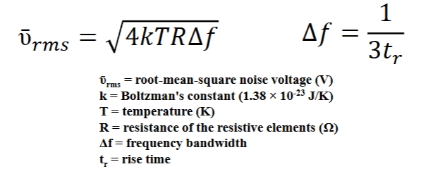
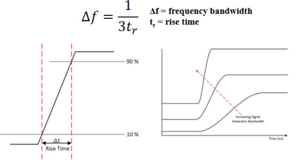
Frequence Bandwidth and Rise Time
Rise time is the time taken by a signal to change from a specified low value (typically 10%) to a specified high value (typically 90%). For example, if the rise time is 0.01 s, the bandwidth is 33 Hz
1st Consideration for Thermal (Johnson) Noise
1) Thermal Noise is independent of the amount of current (flow of electrons) and frequency
2nd Consideration for Thermal (Johnson) Noise
2) The more frequency bandwidth (Δf) the more Thermal Noise. In other words, by decreasing the frequency bandwidth, an instrument becomes slower to respond to signal change and therefore takes more time to make a measurement
For example, decreasing the response time of an instrument from 1s to 1μs (10^-6s). will increase the noise 1000 fold. This assumes that the response time is approximately equal to the rise time, bandwidth has been changed from 1 Hz (1 s) to 10^6 Hz (10^-6 s) thus ῡ𝒓𝒎𝒔 =sqrt (10 6/1)
3rd Consideration for Thermal (Johnson) Noise
3) Thermal noise can be reduced by lowering the temperature of the components.
For example, cooling a UV-visible photodiode array from 298K to 77K will reduce
the thermal noise by 50%.
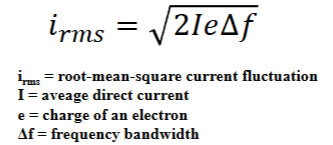
Shot Noise
- Noise caused by electrons or charged particles crossing junctions such as pn interfaces, photocells, vacuum tubes, etc.
- Dependent on number of charge carriers
Consideration for Shot Noise
1) Shot Noise is dependent on the amount of current (flow of electrons)
2) The more frequency bandwidth (Δf) the more shot noise
Flicker (1/f) Noise
Noise characterized as having a magnitude that is inversely proportional to the frequency of the signal being observed.
The cause is not totally understood
Flicker noise becomes important and significant at frequencies below 100 Hz.
Referred to as "pink noise"
Environmental Noise
- Noise from the surroundings.
- Think of each component of an instrument as an antenna
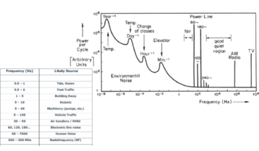
Overall Strategies to Minimize Noise in Hardware
grounding & shielding (both require trial and error for optimum configuration (dark art)), difference amplifier, analog filtering, modulation
grounding
electromagnetic radiation is directed to the ground.
shielding
electromagnetic radiation is direct to the ground before it reaches the components of the instrument.
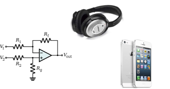
Difference Amplifier
if the noise affects the sample and reference equally, then the noise is not amplified
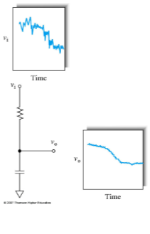
Analog Filtering
RC circuits that only allow certain frequencies to pass.
- Low pass filters pass low frequencies
- High pass filters pass high frequencies
- Notch filters pass specific frequencies
Modulation
move signal to a noise free frequency. Especially useful for flicker (1/f) noise
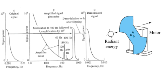
Optical modulation
chopper (modulates signal)
Digital
lock-in amplifier (demodulates signal)
Overall Strategies to Minimize Noise in Software
Convert analog signals to digital signal enables arrays of data and manipulation by software
Strategies include: various types of averaging (ensemble, boxcar, etc.), digital filtering, Fourier transformation, smoother, and correlation techniques.
Software Strategies: Ensemble Averaging
Successive sets of data stored in memory as arrays are collected and summed point by point for averaging. After data collection and summation are complete, the data are averaged
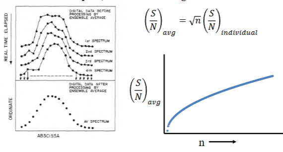
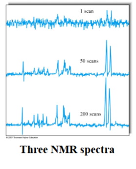
Ensemble Averaging Sample Data
Ensemble Averaging can produce dramatic improvements in S/N.
Random fluctuations in the signal tend to cancel as the number of scans increase, but the signal itself accumulates.
Note: vertical scale is smaller as the number of scans increases.
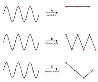
Nyquist Sampling Theory
Sampling must occur at a frequency that is at least twice the highest frequency of the components making up the sample (typically 10× the frequency)
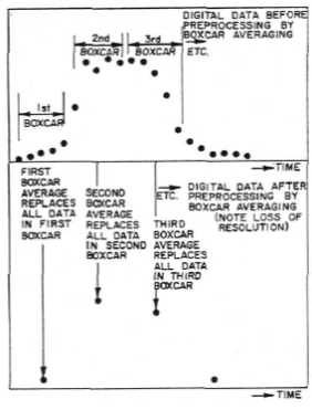
Software Strategies: Boxcar averaging
Smoothing irregularities and enhancing signal to noise with the assumptions:
1) The irregularities result of noise.
2) The signal varies only slowly with time.
3) The average of the small number adjacent points is better measure than a single point.
Example Boxcar with GC Data
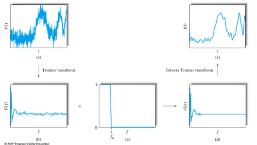
Software Strategies: Fourier Transform (FT)
A spectrum acquired in the time domain is converted into the frequency domain, in which the independent variable is frequency rather than time. The noise peak is digitally filtered out and then converted back into the time domain.