MRI FINAL
1/182
There's no tags or description
Looks like no tags are added yet.
Name | Mastery | Learn | Test | Matching | Spaced |
|---|
No study sessions yet.
183 Terms
For resonance to occur
a RF pulse must be applied at 90 degree from the longitudinal plane at the precessional frequency of hydrogen, gaining transversal magnetization
precession hydrogen at 3T
127.74 MHz
larmour eq
ω = γB
what happens when a RF pulse is applied at 90 degree from the longitudinal plane at the precessional frequency of hydrogen
This places hydrogen into phase. This resultant coherent magnetization precess at the larmour frequency in the transverse plane.
the signal has
a frequency equal to the larmour frequency of hydrogen, regardless of the origin of signal in the patient
The system must be able to locate
signal spatially in three dimensions, so that it can position each signal at the correct point on the image.
How does a system locate signal
first locates a slice. Once a slice is selected, the signal is located or encoded along both axis of the image
three primary functions that gradients perform during MR scanning
slice selection, phase encoding, and frequency encoding
magnetic isocentre
the center point of the axis of all three gradients
what happens in the magnetic isocentre
The magnetic field strength and therefore the precessional frequency remain unaltered here even when the gradients are applied.
first way of selecting slice thickness
We send in an RF pulse that has a range of frequencies.
The wider the range, the thicker slice of protons will be excited
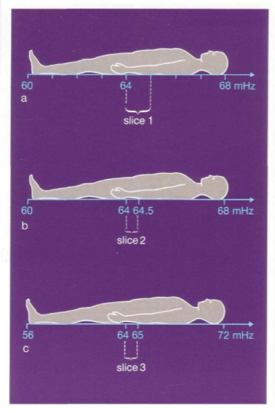
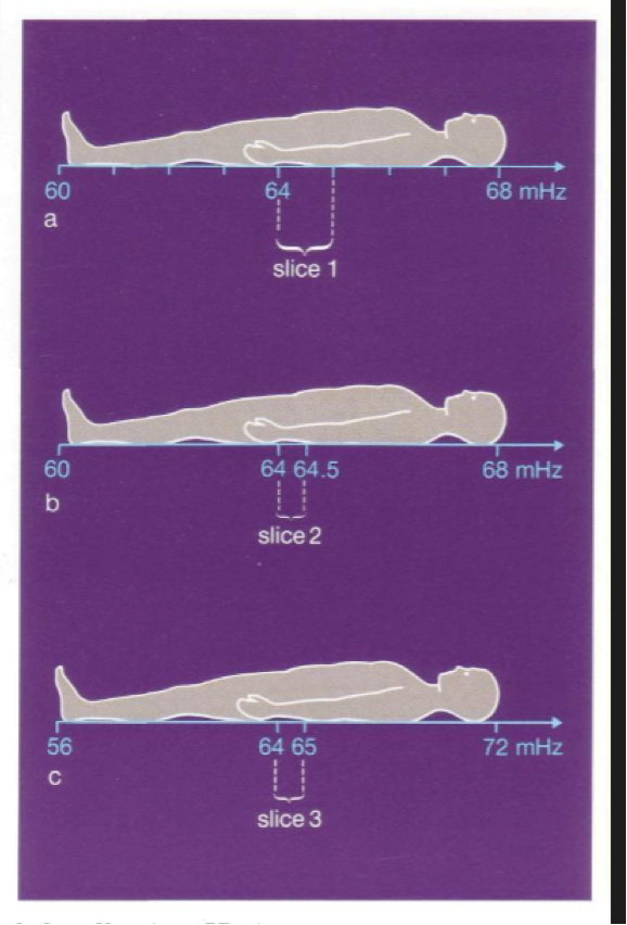
In sequence a, we used a range of RF frequency from 64 mHz to 65 mHz, to produce slice 1
If however in sequence b we use a frequency range from 64 mHz to 64.5 mHz , we will produce slice 2 which is thinner than slice 1
second way of selecting slice thickness
In figure c, we use the same range of frequencies or bandwidth, the slice thickness can be modified by the slope of the gradient
By using a steeper gradient , the precessional frequencies will vary to a larger degree
In figure a and c , the same band width containing frequencies between 64 and 65 mHz was used both times
Because of the steeper gradient in c was used, we produce a thinner slice
To obtain equal resolution in each plane at every angle of obliquity
each voxel must be symmetrical, or isotropic. .
isotropic voxel
voxel has equal dimensions in every plane
anisotropic
the volume has poorer resolution in the planes other than the one that was acquired.
course matrix
one with a low number of frequency and/or phase encoding and results in a low number of pixels in the FOV
for a given FOV a course matrix results in
large pixels and voxels.
fine matrix
one with a high number of frequency and/or phase encoding and results in a large number of pixels in the FOV
for a given FOV a fine matrix results in
small pixels and voxels
pixel
building unit of a digital image
The brightness of the pixel represents
the MRI signal strength generated by a unit volume of patient tissue (voxel).
The voxel represents
a volume of tissue within the patient,
the voxel is determined by
the pixel area and the slice thickness
The pixel area is determined by
the size of the FOV and the number of pixels in the FOV or matrix.
To optimize image quality, the SNR must be
the highest possible
how to get high SNR
Use spin echo pulse sequences where possible
Try not to use a very short TR and a very long TE
Utilize the correct coil
Use of coarse matrix
Use of large FOV
Thicker slices
Use more NEX or signal averages
To improve image quality the spatial resolution must be
high
The spatial resolution can be increased/maintained by
selecting as thin a slice as possible
Selecting a fine matrix
Selecting a small FOV
scan times should be, why
To reduce the likelihood of patient movement, scan times should be as short as possible.
To achieve the shortest scan time
Use the shortest TR possible
Select the coarsest matrix possible
Reduce the NEX to a minimum
SNR is proportional to
Pixel area/FOV squared
Slice thickness
Proton density
NEX
Number of phase encodings (base resolution)
Number of frequency encodings (base resolution)
TR, TE, and flip angle.
spatial resolution determined by
FOV
Matrix size
Slice thickness
scan time is proportional to
TR
Number of phase encodings
NEX
if you increase NEX to maximize SNR what happens
scan time increases
if you decrease matrix to maximize SNR what happens
scan time decreases (p/matrix) and resolution decreases
if you increase slice thickness to maximize SNR what happens
resolution decreases
if you decrease receive bandwidth to maximize SNR what happens
increase the minimum TE and increase chemical shift
if you increase FOV to maximize SNR what happens
decrease resolution
if you increase TR to maximize SNR what happens
decrease T1 weighting and increase number of slices
if you decrease TE to maximize SNR what happens
decrease T2 weigthing
if you decrease slice thickness to maximize resolution what happens
decrease SNR
if you increase matrix to maximize resolution what happens
decrease SNR and increase scan time (p/matrix)
if you decrease FOV to maximize resolution what happens
decrease SNR
if you decrease TR to minimize scan time what happens
increase T1 weighting, decrease SNR, decrease # of slices
if you decrease phase matrix to minimize scan time what happens
decrease resolution, increase SNR,
if you decrease NEX to minimize scan time what happens
decrease SNR, increase movement artifact
if you decrease slice number in volume imaging to minimize scan time what happens
decrease SNR
TR being increased benefits and limitations
increase SNR but Increase Scan time
increase number of slices but decrease T1 weighting
TR being decreased benefits and limitations
decrease scan time but decrease SNR
increase T1 weighting but decrease number of slices
TE being increased benefits and limitations
increased T2 weighting but decrease SNR
TE being decreased benefits and limitations
increased SNR but decreased T2 weighting
increase NEX benefits and limitations
increased SNR but increased scan time
increased signal averaging
decrease NEX benefits and limitations
decrease scan time but decrease SNR and signal averaging
increase slice thickness benefits and limitations
increased SNR but decreased resolution
increased coverage but increased partial voluming
decrease slice thickness benefits and limitations
increased resolution but decreased SNR
decreased partial voluming but decreased coverage
increased FOV benefits and limitations
increased SNR but decreased resolution
increased coverage
decreased Aliasing (pFOV)
decreased FOV benefits and limitations
increased resolution but decreased SNR, decreased coverage, increased aliasing (pFOV)
increase (p)matrix benefits and limitations
increased resolution but increased scan time and decrease SNR if pixel small
decrease (p)matrix benefits and limitations
decreased scan time but decrease resolution
increased SNR if pixel large but decreased resolution
increase receive bandwidth benefits and limitations
decreased chemical shift but decreased SNR
decreased minimum TE but decreased SNR
decrease recieve bandwidth benefits and limitations
increased SNR but increased chemical shift and increased minimum TE
large coil benefits and limitations
increased area of received signal but decreased SNR, more sensitive to artifacts, aliasing with small FOV
small coil benefits and limitations
increased SNR, less sensitive to artefacts, less prone to aliasing with small FOV but decreased area of recieved signal
TR and what it is measured in
TR is the time from the application of one RF pulse to the application of the next RF pulse for each slice and is measured in ms.
what does TR determine
amount of longitudinal relaxation that is allowed to occur between the end of RF pulse and the application of the next
amount of T1 relaxation that has occurred when the signal is read
Echo time
TE: Time in milliseconds from the application of the RF pulse to the peak of the signal induced in the coil
TE determines
much decay of transverse magnetization is allowed to occur
TE controls
the amount of T2 relaxation that has occurred when the signal is read
most common applications for inversion recovery technique
STIR and FLAIR imaging
STIR used where and for what
just about every body part and is known for its uniform Fat Suppression
FLAIR starts with
starts with a 180 degree pulse used to null specific signal
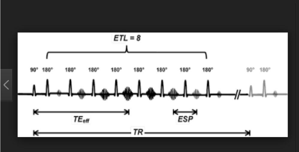
turbo spin echo
spin echo that is much shorter than spin echo.
how does turbo spin echo work
Uses multiple 180 degree rephrasing pulses per TR.
turbo factor or echo train length
The number of 180 rephrasing pulses performed

turbo spin echo
how is a gradient echo created
A magnetic field gradient is applied to refocus the dephasing spins instead of 180 pulse
This means an uneven magnetic field is added onto existing magnetic field
The gradient is switched on for a short time
This creates an even larger increase in field inhomogeneities
Which in turn causes a larger increase in internal magnetic field inhomogeneities inside the tissue slice
This causes the protons in the transverse plane to dephase faster
The magnetic field gradient is switched off
After a short time it is switched on again same strength, but in the opposite direction
Large flip angles produce more
T1 weighting
Longer TE’s produce
more T2* weighting
With fast scans there are often
intense signals from vessels
advantages of gre
Decreased scan time
Increased sensitivity to flow
Volume acquisitions possible
disadvantages of gre
Decreased signal to noise ratio
Increased sensitivity to magnetic susceptibility artifacts
Increased gradient noise
T1 spin echo weighted images are produced using
short TR and short TE
One 180 RF pulse is applied after 90 degree excitation pulse
A short TE in a t1 spin echo ensures
minimal T2 decay
in a T1 spin echo, The differences in T2 time
do not dominate the echo and its contrast
Short TR in a T1 spin echo insures that
T1 time dominates the echo
T2 spin echo created using
a long TR and long TE
One 180 RF rephasing pulse is applied after 90 degree excitation pulse
in t2 spin echo, A long TR
minimizes the T1 contrast
in t2 spin echo a long TE
ensures T2 contrast dominates the echo
phase mismapping
ghosting/ produces replications of moving anatomy across the image in the phase encoding direction
ghosting comes from
anatomy that moves periodically during the scan, such as the chest wall during respiration, pulsatile movement of vessels and CSF, swallowing and eye movement
phase encoding direction can be determined by
the direction of the phase mismapping or ghosting artefact
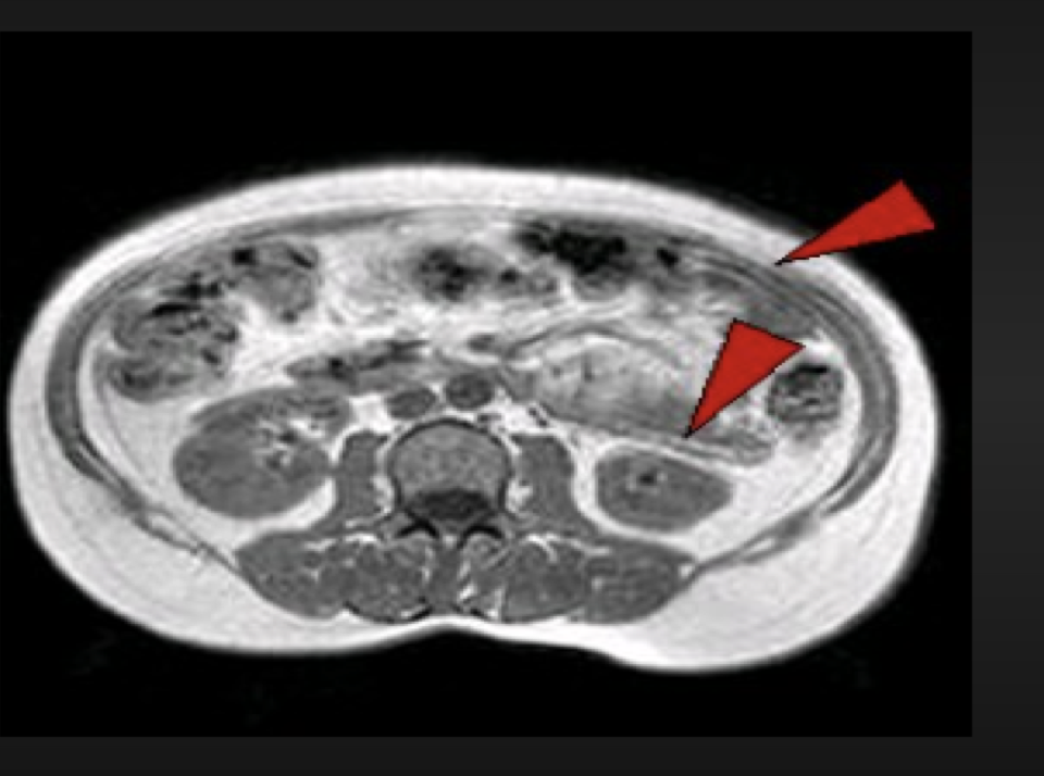
magnetic susceptibility artifact
produces distortion of the image together with large signal voids
magnetic susceptibility
ability of a substance to become magnetized
different tissues magnetize to ______ which results in ____.
what does that cause
Different tissues magnetize to different degrees, which result in different precessional frequency and phase.
This causes dephasing at the interface of these tissues and a signal loss.
the main causes of magnetic susceptibility artefacts are
metal within imaging volume
natural occurring magnetic susceptibility artefact
the iron content of hemorrhage, as these magnetize to a much greater degree than the surrounding tissue.
Ferromagnetic objects have a very high
magnetic susceptibility and cause image distortion.
Magnetic susceptibility artefact is more prominent in ______ because
gradient echo sequences bc gradient reversal cannot compensate for phase difference at the interface.
ways to fix magnetic susceptibility artefact
Remove all metal objects. Always ensure the patient has removed all metal objects when possible before the scan.
Use turbo or fast spin echo sequences instead of gradient echo. The multiple 180 degree rephasing pulses is very effective at compensating for phase differences between fat and water. Gradient echo is very poor at this.
Decrease the TE. Longer echo times allow for more dephasing between tissues with susceptibility differences, therefore using a short TE reduces this artefact. Broad receive bandwidths also reduce the TE.
aliasing/wrap artefact
Wrap or aliasing produces an image where the anatomy that exists outside the FOV is folded onto the top of the anatomy inside the FOV.