combine
1/50
There's no tags or description
Looks like no tags are added yet.
Name | Mastery | Learn | Test | Matching | Spaced | Call with Kai |
|---|
No analytics yet
Send a link to your students to track their progress
51 Terms
Operational Amplifier =
amplifies voltage difference by A₀ (open-loop gain)
V_out = A₀(V₊ − V₋)
A₀ (open-loop gain) is very large: ~100k to 100M V/V
3 Ideal Op Amp assumptions =
1. No current into inputs: I_in = 0
2. Output can drive infinite current: I_out → ∞ (current comes from supply rails)
3. Open-loop gain is infinite: A₀ → ∞
Op amp V_out is always limited by =
Supply voltages
(Will get clipping if Vout exceeds Vs)
If Op-Amp has CLNF, what can be assumed =
V₊ = V₋
ONLY valid with negative feedback present (Vout connected to V-).
Noninverting amplifier gain + circuit =
A = 1 + [R_f / R_i] Gain is ALWAYS ≥ 1
Output same polarity as input.
![<p>A = 1 + [R_f / R_i] Gain is ALWAYS ≥ 1</p><p>Output same polarity as input.</p>](https://assets.knowt.com/user-attachments/a3768c22-79c3-4f73-ace2-db2b1c4e9c8f.png)
Opamp Gain Formula =
V_out/V_in
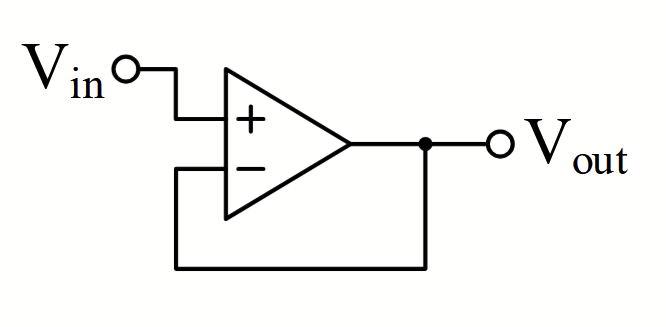
Unity gain buffer/voltage follower gain + circuit =
A = 1
Inverting amplifier gain + circuit =
A = −[R_f / R_i]
![<p>A = −[R_f / R_i]</p>](https://assets.knowt.com/user-attachments/5c10cbb9-19b1-4032-be8e-2a62a48497cf.png)
Difference amplifier Vout and circuit =
V_out = (V_in+ − V_in−) × [R_f / R_i]
Amplifies the difference between two inputs.
Uses MATCHED resistor pairs, voltage divider configuration (R_i on both inputs, R_f on both feedback paths)
![<p>V_out = (V_in+ − V_in−) × [R_f / R_i]</p><p>Amplifies the difference between two inputs.</p><p>Uses MATCHED resistor pairs, voltage divider configuration (R_i on both inputs, R_f on both feedback paths)</p>](https://assets.knowt.com/user-attachments/4599ed4b-4000-44e9-8a4f-5a31aeeadcdb.png)
Inverting summing amplifier =
V_out = −R_f × ([V_in1 / R_i1] + [V_in2 / R_i2] + ... + [V_inN / R_iN])
Multiple inputs through separate R_i's to V-, single R_f in feedback.
![<p>V_out = −R_f × ([V_in1 / R_i1] + [V_in2 / R_i2] + ... + [V_inN / R_iN])</p><p>Multiple inputs through separate R_i's to V-, single R_f in feedback.</p>](https://assets.knowt.com/user-attachments/315d4c38-26c0-46a5-960a-5216cedfefb1.png)
Noninverting summing amplifier =
V_out = (1 + [R_f / R_i]) × (Req) × (V_in1 + V_in2 + ... + V_inN)
Where R_i is the feedback-to-ground resistor.
V₊ = average of inputs if ALL input resistors are EQUAL.
![<p>V_out = (1 + [R_f / R_i]) × (Req) × (V_in1 + V_in2 + ... + V_inN)</p><p>Where R_i is the feedback-to-ground resistor.</p><p></p><p>V₊ = average of inputs if ALL input resistors are EQUAL.</p>](https://assets.knowt.com/user-attachments/b85edf8e-7e99-4e78-9abb-d28c43aea50c.png)
Which opamps have + top / - top?
+ top
noninverting amp
noninverting summing amp
voltage follower
- top
difference amp
inverting amp
inverting summing amp
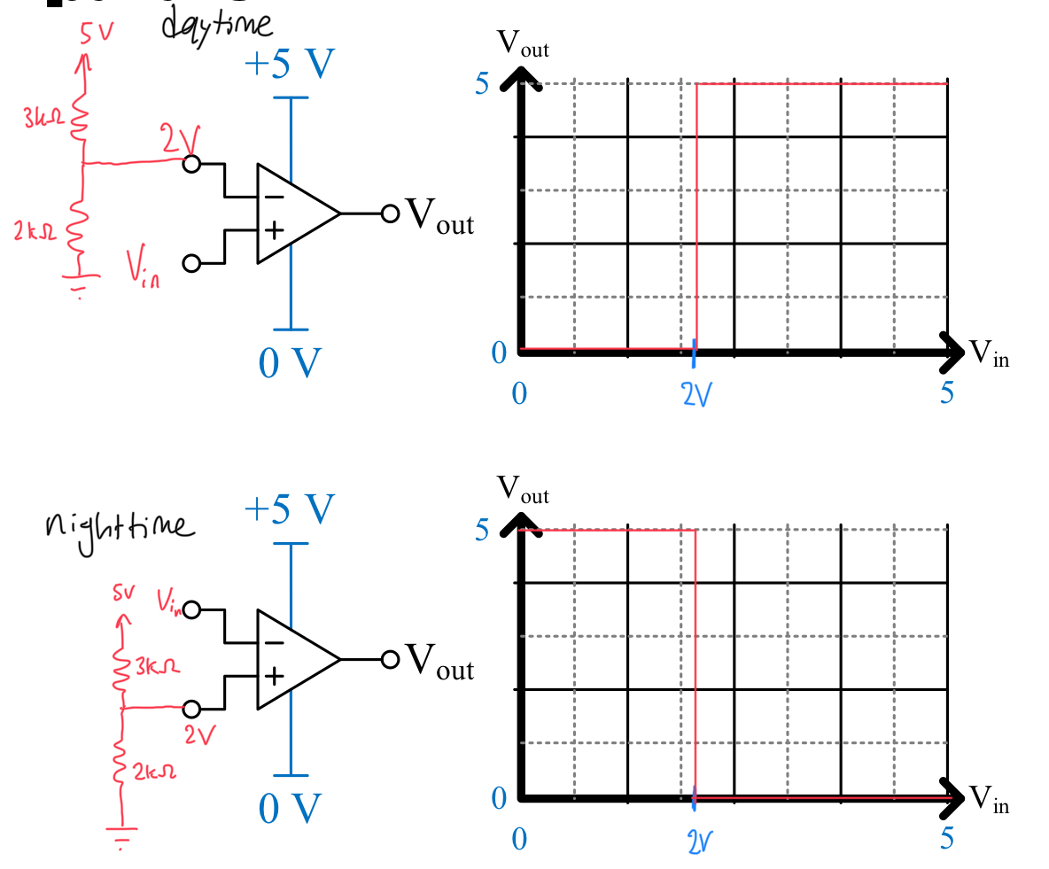
Comparator =
Open-loop (no feedback)
Output hits the supply rails:
V_out = V_DD if V₊ > V₋
V_out = V_SS if V₊ < V₋
Compares two analog signals → digital output.
V_DD and V_SS =
V_DD = positive Voltage
V_SS = negative Voltage
How to tell which rail will saturate =
look at where Vin enters (V+ or V-)
V+ = non inverting = same sign as Vin
V- = inverting = opposite sign as Vin
What does || mean =
Parallel
R1 || R2 = R1R2/(R1 + R2)
Voltage divider formula =
Given resistor R1 on top, R2 on bottom, Vout is in the middle node
Vo = Vi[R2/(R1+R2)]
For multiple resistors, add all of them on denominator, only Rx is added to numerator where Rx is the node Vout measured from
Current divider formula =
Given resistor R1 on the left, R2 on the right, Io is on the right
Io = Iin[R1/(R2+R3)]
For multiple resistors, simplify with Req
Wheatstone bridge formula =
Given source Vs
V is the voltage between the two middle nodes of voltage dividers
Rx is the bottom right, unknown resistor
V = VsRx/(Rx + R2) - VsR3/(R1 + R3)
Two parallel voltage dividers, in diamond pattern
supernodes method =
create a boundary around a Voltage source, then apply KCL so you can ignore the Voltage source
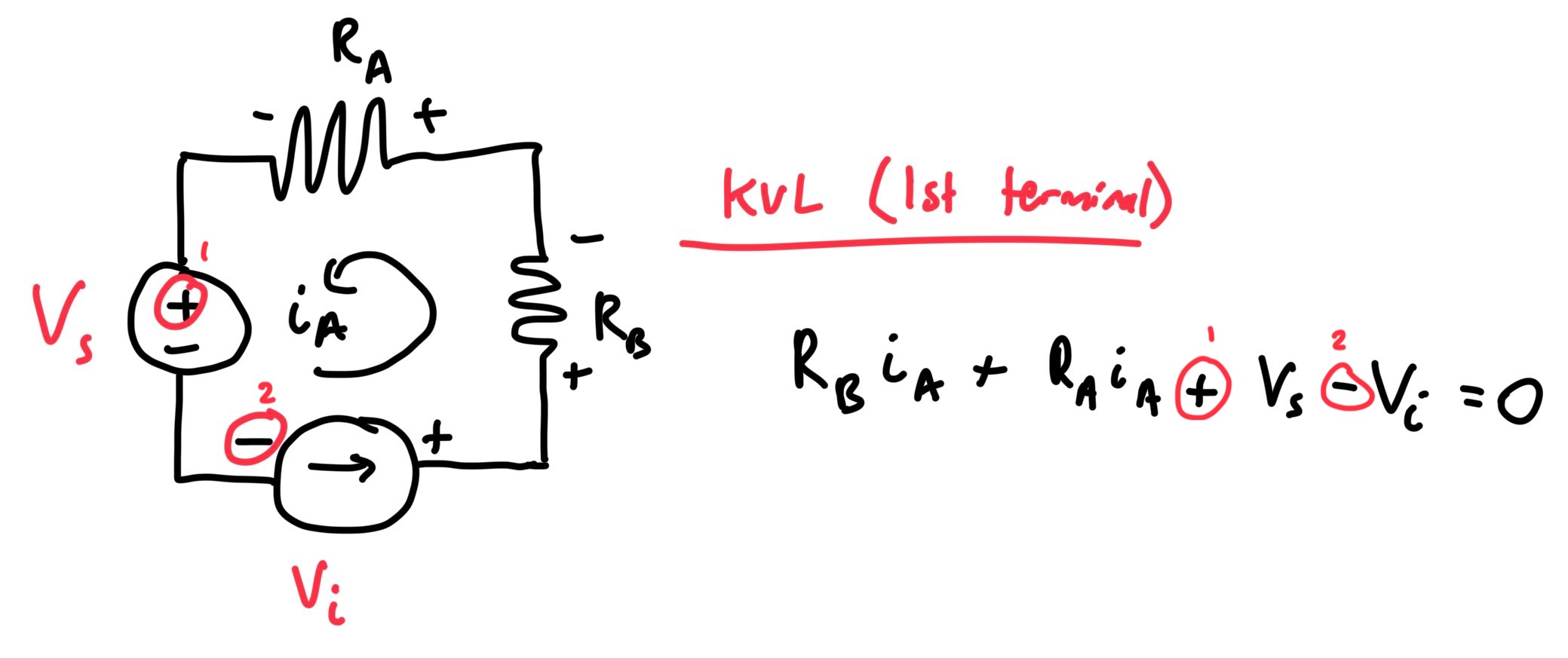
mesh current method =
create loops for KVL and solve
components in between two loops will be a sum of currents
supermeshes method =
creating boundary around a Current source, then apply KVL so you can ignore the Current source
removing a voltage source, circuit becomes ???
short circuit
removing a current source, circuit becomes ???
open circuit
thevenin circuit =
voltage source + resistor in series, Vopen = Vth
norton circuit
current source + resistor in parallel, Ishort = In
what maximizes power in a thevenin circuit =
Rload = Rth
superposition method =
linear circuits, can consider independent sources one at a time and sum them all up
dependent sources MUST BE KEPT
how many KCL eqns in a circuit
N - 1
N = # of nodes
how many KVL eqns in a circuit
B - N + 1
B = # of branches / components
N = # of nodes
for mesh analysis, how to figure out polarity of V_drop =
look at loop current, the terminal it enters is the sign
how to know if component is absorbing/delivering power =
P > 0 = absorb
current going INTO positive terminal
P < 0 = deliver
current going OUT OF positive terminal
passive sign convention =
label current into positive terminal as positive
Define DC =
direct current
Current and voltage is constant
define AC =
alternating current
Current or voltage varies over time (not constant)
define Vpk =
how far AC component gets away from DC
define Vpk-pk =
max V - min V
How to convert from frequency to angular frequency
ω = 2πf
How to draw dependent vs independent source =
dependent = diamond
Independent = circle
Define conductance =
inverse of resistance (G = 1/R)
How well a resistor conducts electricity
Unit is Siemens (S)
Resistor has 2 ohms or 0.5 Siemens
what are E series resistors =
resistors split up into X equally spaced (logarithmic) values
ex.) E24 series
Values are from 10^(X/24)
how to combine parallel resistors to one =
For two parallel resistors
1/Req = 1/R1 + 1/R2
how to combine series resistors to one =
add them up
how to combine voltage sources =
in series ONLY
how to combine current sources =
in parallel ONLY
Kirchoff's current law =
current into a node = current out of a node
Kirchoff's voltage law =
sum of all voltage rises and drops in a closed loop circuit is 0
Current formula =
I = dQ/dt
Current in parallel is =
Current in series is =
Current adds up in parallel
(It = I1 + I2 + I3...)
Current is the same in series
(It = I1 = I2)
Voltage in parallel is =
Voltage in series is =
Voltage is the same in parallel
(Vt = V1 = V2 = V3)
Voltage is split in series
(Vt = V1 + V2 + V3)
how to know if components are in parallel/series/neither =
parallel = both common nodes
Series = 1 common node with NO additional branches