BME 311 Lecture 4
 Call Kai
 Learn
Learn Practice Test
 Spaced Repetition
 Match
Match Flashcards
 Knowt Play
1/27

There's no tags or description
Looks like no tags are added yet.
Name | Mastery | Learn | Test | Matching | Spaced | Call with Kai | Chat |
|---|
No analytics yet
Send a link to your students to track their progress
28 Terms
absorption of energy and radiation dose
fluence Φ = photons/area (cm-2) passing through a surface
fluence rate = flux = (photons/area)/time
energy fluence ψ = energy/area = (photons/area) x (energy/photon) = ΦE (keV/cm2)

exposure - amount of electrical charge (ΔQ) produced by ionizing radiation per mass of air exposure ; X = ΔQ/ Δm (C/kg) – historical unit roentgen (R)
1 R = 2.58 × 10⁻⁴ C/kg
defined because it’s easy to measure for a beam, used in calibrating instruments
not as meaningful for understanding biological effects

equivalent dose
dose modified to reflect the relative “effectiveness” of the type of radiation in producing biologic damage
radiation weighting factor (wR) established by International Commission on Radiological Protection (ICRP)
H - W wR
SI unit = sievert (Sv)

effective dose
may vary across body
want single number to characterize risk to whole body
not all tissues equally sensitive to effects of ionizing radiation
tissue weighing factor (wT) established to assign a particular organ or tissue (T) its vulnerability to radiation
effective dose = sum of products of equivalent dose to each organ or tissue irradiated and corresponding weighting factor
most related to increase in cancer risk = ~0.004%/mSv
typical radiology exam 1-10 mSv, max worker = 50 mSv annually
E(Sv) = ΣwT x HT (Sv)

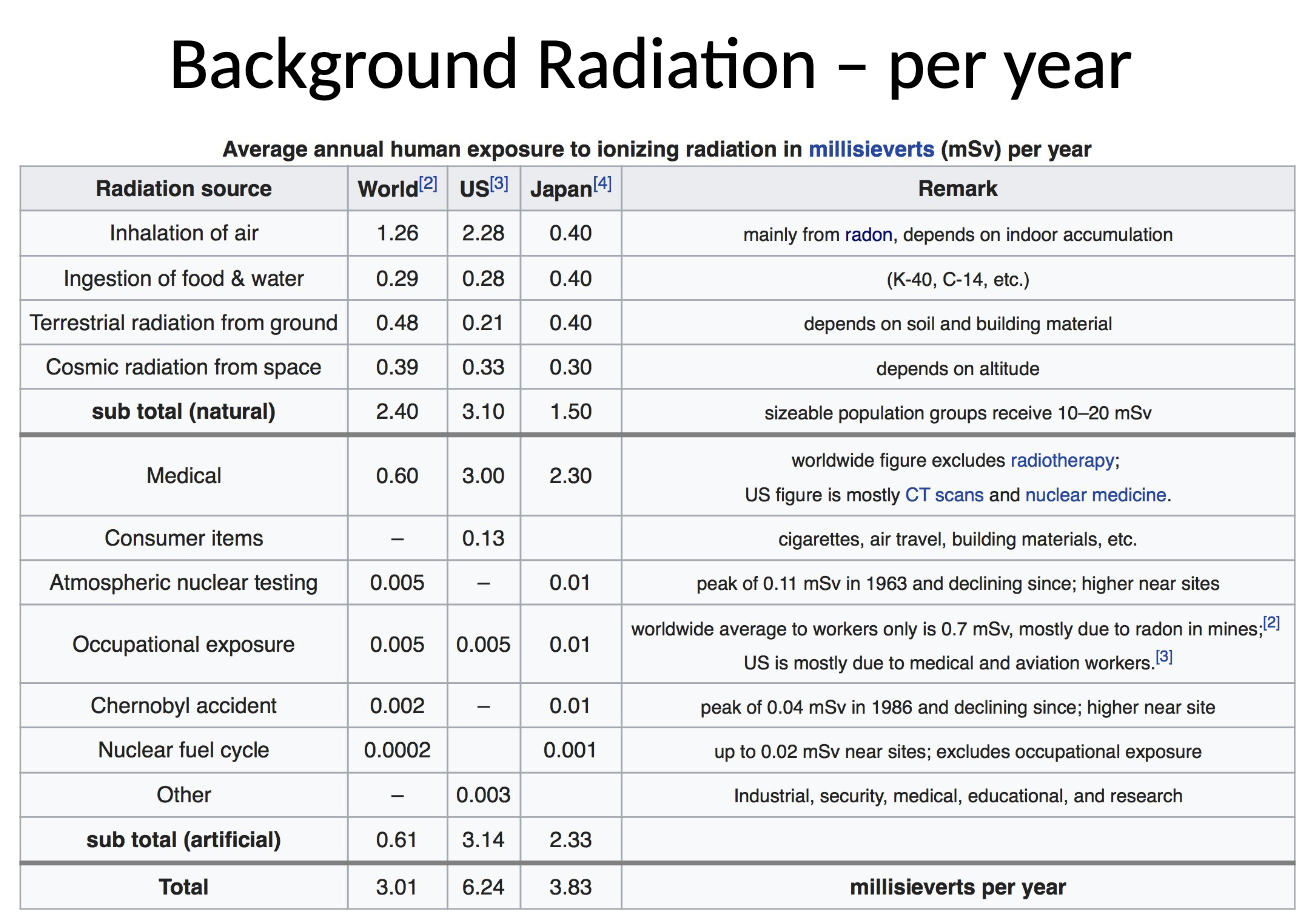
risk estimates assume most conservative model
cumulative, linear, no-threshold
data from A-bomb in Japan
small doses (<50mSv) not proven to be harmful
assumptions are to be on safe side

radiation risks in perspective
effective dose is most closely related to increase of overall lifetime cancer risk = ~0.004%/mSv
radiological procedures ~10 mSv means increase from ~20% normal lifetime risk of cancer to 20.04% (1 in 2500 increase)
radiation workers allowed 50 mSv max/year
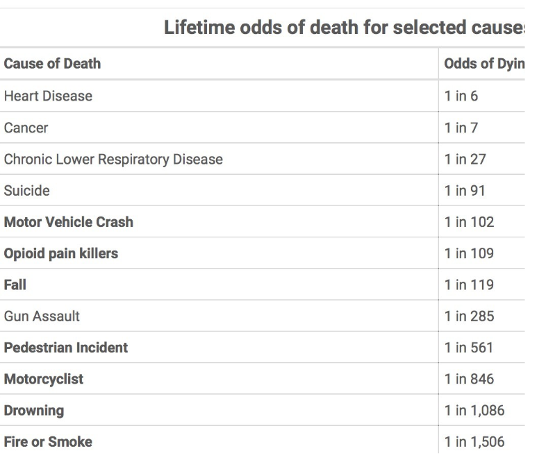
x-rays are generated in an x-ray tube, which consists of
a vacuum tube with a cathode and anode;
cathode current for thermionic emission (~5A)
tube voltage for electron acceleration (20 kV-150kV)
kinetic electron energy gained = qV so in units of keV (20 keV to 150 keV);
resulting “tube current” from cathode to anode (~100mA)» what produces x-rays

heat dissipation electron-anode interaction
a high speed electron can collide with an outer shell electron
secondary electron is the finally dissipated into heat
most electron beam energy is lost this way
cooling of anode is essential
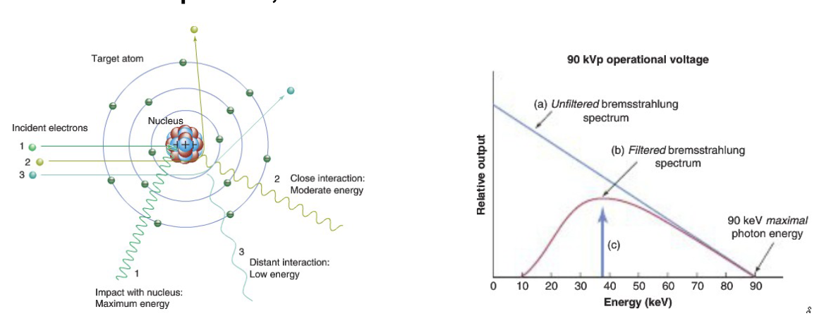
bremsstrahlung (braking) radiation electron-anode interaction
interaction with a nucleus (much larger than an electron)
covers entire spectrum, and energy of bremsstrahlung photons is bounded by E≤ Emax = qV, e.g., for V=90 kV, Emax=90 keV
continuous spectrum, keV is convenient unit
characteristic radiation electron-anode interaction
an electron can collide with an inner shell electron (eg. rom the K shell) and eject it, leaving a hole
this hole is refilled when an electron of higher energy (eg. from L shell) drops into the hole while emitting a photon of a very specific energy
the energy of this photon is the difference between the two electron state energies
such transition yields characteristic peaks in the x-ray spectrum
K series, L series

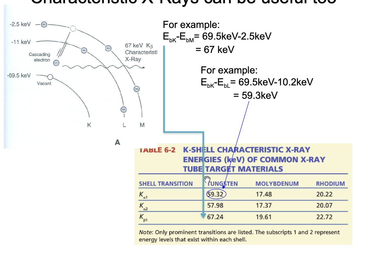
characteristic x-rays can be useful too
x-ray tubes

tube current vs. filament current
filament current determines temperature - rate of thermionic electron emission
small change in filament current can produce relatively learge change in tube current
tube current determines x-ray intensity
saturates/plateaus
electrons usually considered independent of each other
but at high cathode currents, electron cloud builds around the filament, called “space charge”, repelling electrons from each other

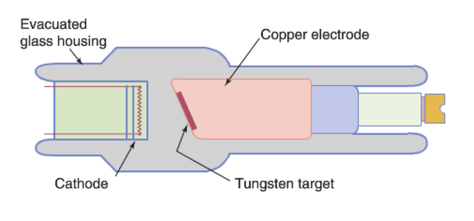
fixed anode
copper supports tungsten target and removes heat
small target area limits heat dissipation rate and thus, limits maximum tube current, x-ray flux
dental x-ray units, portable x-ray units use fixed anode x-ray tube
rotating anode
allow greater heat loading and consequently higher x-ray output
rotation speed - 3000 - 10000 rpm
still gets hot - lots of thermal engineering here
CT scanners use these
x-ray tube housing
supports, insulates and protects x-ray tube insert from the environment
lead shielding inside the housing attenuates x-ray emitted in all directions
hole in the shield at x-ray tube port

collimators
adjust size and shape of x-ray field emerging from the tube port
bea, of light reflected by the mirror mimics the x-ray beam - identifies the collimation from the shadow

x-ray generator components
x-ray generator, x-ray tube

power rating of an x-ray tube
is the maximal power that an x-ray tube focal spot can accept or the generator can deliver
power = tube voltage x tube current
so for 100 mA = 0.1 A tube current at 100 kV
power = 100 kV * 0.1 A = 10kW but for short bursts
factors affecting x-ray fluence
target material (anode)
mainly proton number as Z2
tube current (mA) which depends on
cathode current
tube voltage as kVp2
exposure time (sec)
the duration of x-ray production (sec)
often combined with tube current as mAs = milliamp-seconds ~ number of electrons used
mAs most useful for operator/technologist since they control it
beam filtration
x-ray quantity = fluence
depends on Z2 x mAs (which is a function of kVp² and cathode current and exposure time)
filtration
when the x-ray beam is produced, many energies of photons exist. many are of such low energies that they will offer nothing to the production of the radiograph
metals such as aluminum will absorb the soft low energy rays
the purpose of the filtration is to reduce the patient exposure and “beam hardening” which causes artifacts in CT imaging

inherent filtration
thickness (1-2 nm) of glass at x-ray tube port
additional filtration
added glass and aluminum - effectively attenuate x-rays below 15 keV
other common filter materials - copper and plastic (acrylic)

beam hardening
low energu (soft) x-ray will not penetrate most tissues
soft photons preferentially removed, leaving more “hard” ones
shift to higher average enrgy as the beam traverses matter - beam hardening
beam intensity drops, but effective energy increases
filtering results in x-ray beam with higher effective energy/HVL
when it occurs in the body, can cause artifacts in CT imaging

beam hardening vs beam filtering
changing shape of energy spectrum by preferential absorption of low energy photons in the beam
hardening
occurs in patient
not desirable in CT because image reconstruction algorithms assume that beam energy does not change as it goes through the body
mitigate by narrowing spectrum of x-rays going into patient
filtering
purposely added material in front of beam to change shape of spectrum
removes lower energies which add dose to patient but don’t contribute to image (most would be absorbed by body)
can also remove high energies that have poor contrast for the imaging situation (like mammography)
reduces beam hardening effect in body - like pre-hardening the beam