Artifacts
1/100
There's no tags or description
Looks like no tags are added yet.
Name | Mastery | Learn | Test | Matching | Spaced |
|---|
No study sessions yet.
101 Terms
Lower field strength systems are defined as those operating below
1 T
High field strength systems are defined as those operating below
1-3T
Ultra-High field strength systems are defined as those operating below
7T
Digital magnetic resonance imaging systems realize an SNR boost of
30-40%
Those at higher risk for SAR thermal heating include
obese, hypertensive, geriatric, and diabetic patients, patients on sedatives, beta blockers, and diuretics
function of the gradient magnetic field
create the image orientation and the spatial resolution (detail) used to distinguish adjacent or abnormal structures
slice select gradient
main function of determining slice thickness, scan plane and orientation of a pulse sequence
frequency encoding gradient
responsible for the encoding in the long axis of anatomy, is not a direct contributor of scan time, and is on during the sampling of the MR signal echo
frequency encoding gradient is on when
during the sampling of the MR signal echo
phase encoding gradient
plays a pivotal role in shaping the image detail and scan time, as this gradient switches on and off to fill lines of k-space.
Common methods of scan time shortening include
fast spin echo sequences, halfscan, rectangular field-of-view (rFOV), and parallel imaging
each additional 180° RF pulse in this sequence implements ______ times the SAR power compared to the initial 90° RF excitation pulse
four
Halfscan
scan time shortening technique whereby the phase encoding process is shortened using assumed filling of k-space. ~60%
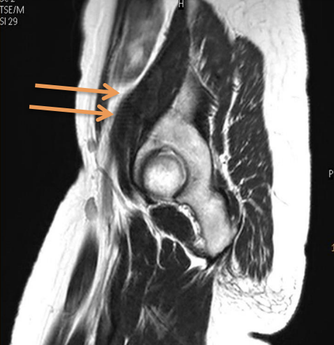
specific location where aliasing artifacts arise
the outer edges of each image
where the data misregistration of anatomical location in the phase direction takes place, outermost edges of the image, working inward based on the severity of the phase direction undersampling
aliasing corrective measures
“no phase wrap” or “anti-aliasing” options, or an increase in phase dimension sampling
Parallel Imaging
takes advantage of RF phased array coil elements and channels to sample data in parallel
how does parallel imaging reduce scan time
how does reducing number of times phase encoding steps performed reduce scan time
Higher parallel imaging factors result in
shorter scan times, slightly reduced SNR and greater potential for artifacts
The two main advantages of selecting parallel imaging options are
the reduction in gradient switching and the lack of additional RF power required performing the acceleration technique
Two main approaches to parallel imaging are rooted in
the method of data collection
Image based Methods of parallel imaging
that reconstruct images from each coil element within a reduced FOV then merge the images with the knowledge of collected coil sensitivities (reference scan (GRE))
ASSET, SENSE, mSENSE, Speeder, Rapid
K-space based methods of parallel imaging
that explicitly calculate missing kspace lines before Fourier transformation of the raw data
SMASH, GRAPPA/iPat,
Vendor Parallel Imaging GE
ASSET: Image
SMASH: K-space
Vendor Parallel Imaging Phillips
SENSE: Image
Vendor Parallel Imaging Siemens
GRAPPA / iPat: K-space
mSENSE: Image
Vendor Parallel Imaging Toshiba
Speeder: Image
Vendor Parallel Imaging Hitachi
Rapid: Image
prerequisites exist for parallel imaging techniques to be considered
a gradient echo based reference scan or calibration scan is prerequisite to collect tissue data within phased array coil element, dedicated, RF phased array coil
dedicated, RF phased array coil
contains multiple elements of small RF coils, generating larger anatomic coverage capabilities
parallel imaging artifcsats look like
resulting in a mis-representation of the patient’s tissue, typically in the central portions of the image
Parallel imaging artifacts occur when
the FOV is too small for the parallel imaging factor selected,
parallel imaging reduction factor too high for the parameters and FOV selected
Parallel imaging artifacts occur in what direction
phase encoding direction, slice select dimensions
corrective measures for parallel imaging
Increase FOV or reduce parallel imaging factor
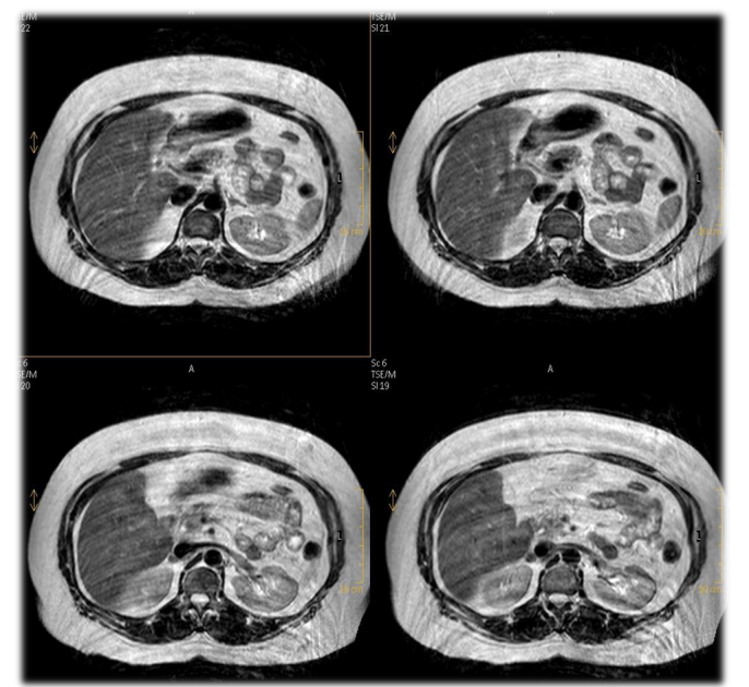
what cases should you be careful when reducing parallel imaging factor
abdominal MRI because of breath holds
Parallel Imaging artifact Corrective Measures
increase FOV maintain voxel size, increase FOV maintain phase matrix, decrease parallel imaging factor
In parallel imaging if you Increase FOV and maintain voxel size
increased scan time, no change on detail, longer scan time with increased matrix
In parallel imaging if you increase FOV maintain phase matrix
no change scan time, less detail, Maintained scan time with decreased spatial resolution (detail)
In parallel imaging if you Decrease Parallel Imaging Factor
Increased scan time, Unchanged detaill, Increased SAR absorption, Longer scan time
what intrinsic factor does not affect chance of parallel imaging factor from showing up
Using a system with lower field strength or fewer channels does not increase the chance for artifact potential
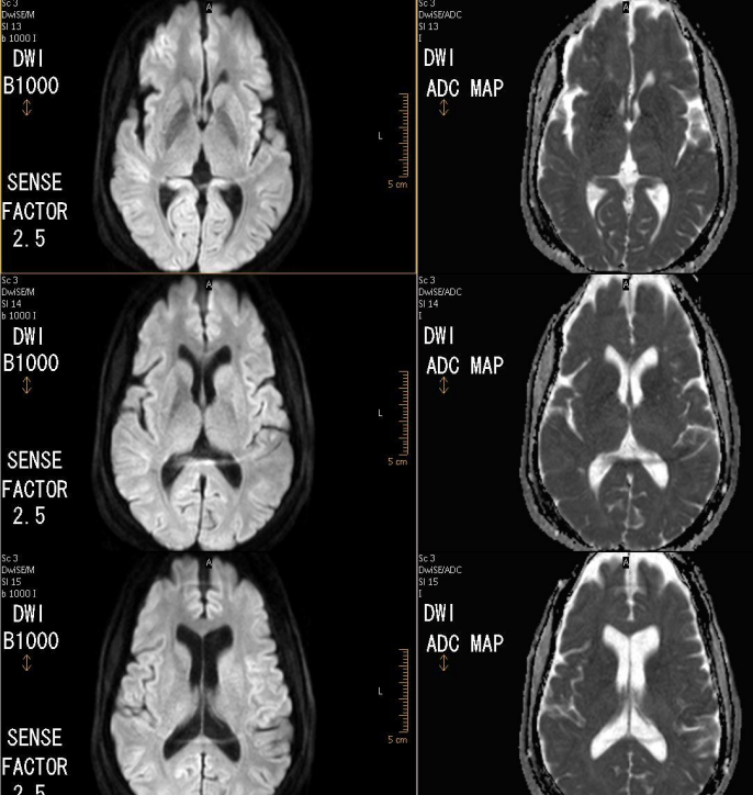
parallel imaging artifacts in DWI look like
reduce the susceptibility effects in diffusion weighted images, especially around air-tissue interfaces
Parallel imaging artifacts in the slice select direction are found where
in the first and last slices of image acquisition in a 3D volume data set
Parallel imaging artifacts in the slice select direction are reduced by and what are the tradeoffs
reduction in Slice direction parallel imaging factor, which will result in longer scan times and improved signal-to-noise ratios
Any reduction in the parallel imaging R factor will result in
more signal, less noise and fewer centrally located artifacts.
what prohibits use of parallel imaging
stimulators that need T/R coils, metal artifact reductio
Certain patients that have surgically implanted stimulators (such as a vagus nerve stimulator, or certain spinal cord stimulators) can only be imaged with and why
a dedicated, transmit-receive coil
its not equipped with multiple RF coils, nor can parallel
bariatric pts and using parallel imaging
increased SAR possibilities
artifacts
signal misrepresentations that do not correspond to the spatial location of the specific tissue imaged.
primary contributor of noise in an MRI system
pt
secondary contributor of noise in an MRI system
system equipment
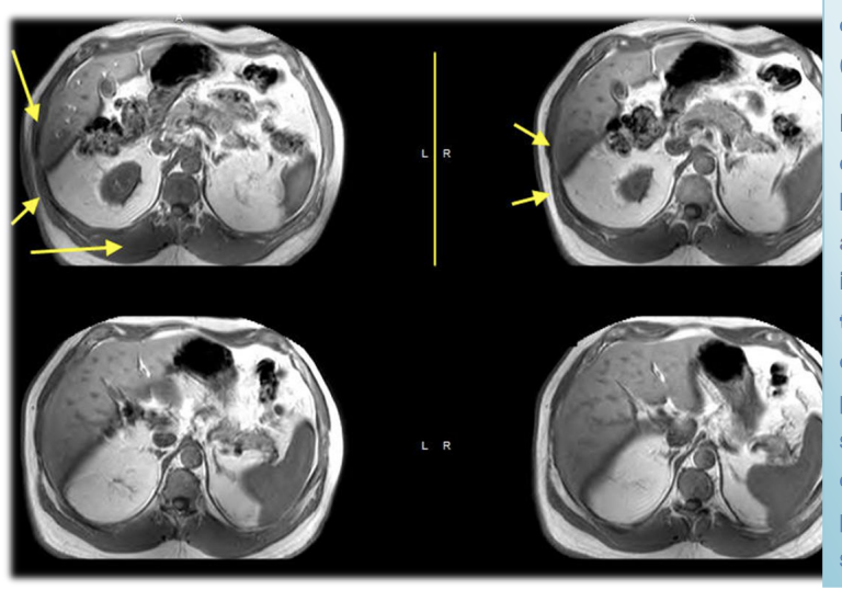
motion
smearing across the image in the phase encoding direction
what can reduce motion artifact
Triggering, radial k-space acquisition techniques, reduction in signals averaged, or utilization of parallel imaging techniques
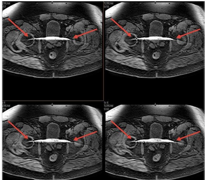
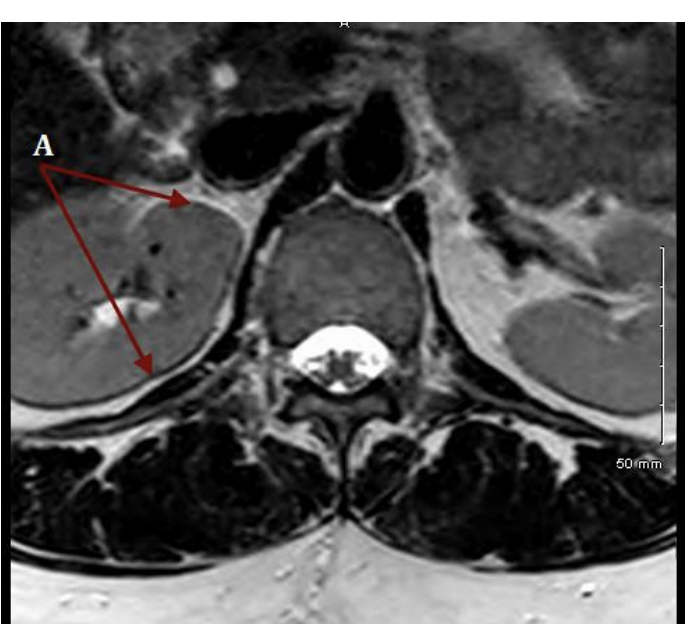
Chemical shift artifact occurs because
fat and water precess at different frequencies
chemical shift occurs where
along the frequency axis
what is used for the reduction of chemical shift artifacts
higher bandwidth
Chemical shift misregistration artifact looks like
bright or dark outlines predominantly at fat / water interfaces
chemical shift is present in what body part mostly
kidney, optic nerve or small disc herniation
Higher field strengths will create more chemical shift artifacts due to
the increased separation of fat and water frequencies.
Inhomogeneities can lead to
poor fat suppression, limits in field of view and challenges in off-isocenter imaging especially in extremity MRI procedures.
Increasing parallel imaging factors can decrease ________ where ______
susceptibility artifacts around air tissue interfaces, such as temporal bone/auditory canal regions.
why is GRE more susceptible to metal artifacts
due to the lack of 180° refocussing pulse that would reduce field inhomogeneities.
When the TE is shortened, susceptibility artifacts ____ bc _______
decrease because shortened TE's allow less time for dephasing thus reducing signal loss.
To decrease magnetic susceptibility
utilize smaller voxels, shorter TE, and increased receiver bandwidth, use FSE and SE bc lots of 180 pulses correct for inhomogeneities and local field distortions
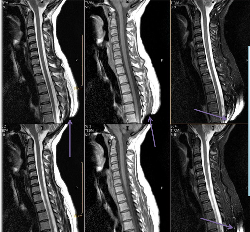
Gradient moment nulling (or flow compensation)
correcting for constant velocity (first order) motion distortion in standard spin echo or gradient echo pulse sequences
flow compensation used where
used in a cervical spine MRI to minimize CSF flow artifacts
how does GMN work
In spin echo and gradient echo sequences, the first moments of the imaging gradients are zeroed at the echo time to cancel out the accumulation of phase due to movement
goal of GMN
minimize the phase shifts obtained by the transverse magnetization of excited nuclei moving along the gradients (including the effect of refocusing RF pulses), useful in reducing image artifacts due to fluid motion
first order motion exs.
constant velocity (peripheral small vessels, CSF, etc).
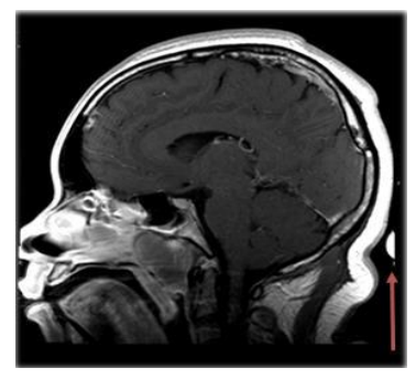
zipper artifact
leak in the RF shielding can appear as a zipper artifact in the phase or frequency encoding direction. Ensure adequate door suction in the MR scan room
to correct for Gibbs artifact
increase the number of phase encodings or reduce the FOV (while maintaining matrix)
truncation can mimic what pathology
syrinx in cervical spine
gibbs truncation or ringing artifact
seen as bright or dark lines parallel and adjacent to borders of distinct intensity change
how does gibbs artifact occur
when a small matrix is used, incompletely digitizing the echo by the end of the acquisition.
Partial volume averaging
when multiple tissue types are contained within a single voxel
wshat slices contribute to partial volume averaging
Thicker slices contribute more heavily to partial volume averaging
where does partial volume averaging take place
slice select direction of the image
A ____ in the voxel volume yields a _____ in partial volume averaging artifacts, with ______ slice thickness being the easiest solution.
decrease, decrease, thinner
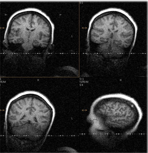
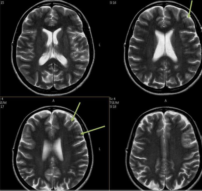
Dielectric effects caused by
caused by local eddy currents due to the increased conductivity of body tissue
dielectric effect looks like
areas of shading or signal loss
Cross talk artifact, slice overlap artifact, occurs when
slices overlap or are too close together
what does cross talk create and where is it found
“band” of signal loss, usually found posteriorly and working its way anterior towards the spinal canal in a lumbar spine, multi-stack axial acquisition
The severity of the cross talk is directly proportional to
the amount of slice overlap.
Corrective measure for cross talk
increase gaps between the slices, to reduce the slice overlap, or utilize a “stacks as packages” function on the scanner
how can BLADE / Propeller / MultiVane help with artifacts
technique of filling k-space aids in correcting patient motion, flow artifacts, and, according to this article, correct for crosstalk artifacts.
Cross excitation artifacts deal with
subsequent, consecutive slices in a multi-slice acquisition
Cross excitation artifacts due to
signal loss due to partial saturation in adjacent slices. This is due to the partial excitation and subsequent saturation of adjacent slices in multi-slice imaging.
what sequences does cross excitation occur most
STIR
guidelines for metal artifact reduction
Use Fast Spin Echo in place of Gradient Echo sequences, the 180º RF refocusing pulses will help to correct for metal susceptibilities
Do Not Use Parallel Imaging Techniques or Image Uniformity correction options as they require Gradient echo reference scans
Use high TSE Factors (long ETL) in Fast Spin Echo, the 180º RF refocusing pulses will help to correct for metal susceptibilities [27, 28]
Use a wide receiver Bandwidth (rBW) / small Water Fat Shift to reduce the chemical shift, minimize the metal artifact [27, 28]
Use a thin slice thickness to reduce the partial volume artifact, thus reducing the amount of metal artifact
Use STIR sequences in place of Fat Suppression to further enhance the reduction of metallic susceptibility artifacts
Maintaining good SNR is key to adequate MARS imaging; increase NSA/NEX to add signal, MARS sequences are not fast!!
Metal Artifact Reduction Summary
• Use TSE over Gradient Echo
• Use STIR instead of Fat Suppression techniques
• Utilize Wide rBW (receiver Bandwidth)
• No parallel imaging or image uniformity correction
• Thin slices
• Small pixel size/large matrix
• High TSE factor/ ETL
• Add NEX/NSA to buy back signal, restore IQ
moire fringes artifact caused by
interference of aliased signals at different phases
moire fringes artifact seen in
3D gradient echo images at higher field strengths, when larger field of views are utilized
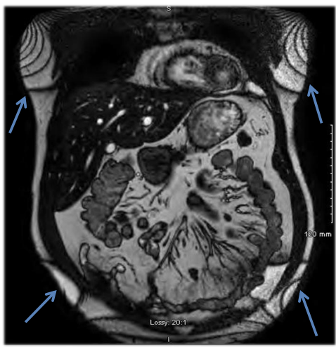
moire fringe aka
zebra artifact
what can correct for FID artifacts
Increase in NEX and/or the enabling of Flow Compensation
fine-line artifacts look like and originate from
give the appearance of Gibbs-like artifacts,
originate from an incompletely crushed FID signal from an RF refocusing pulse
where are FID artifacts common in
FSE / TSE sequences because of their pulse sequence design and their high SNR
contributing factors to fine-line artifacts
reduced refocusing pulses, increases in FOV, and decreases in slice thickness
magic angle arttifact occurs when
a tendon or ligament is positioned approximately 55° to the direction of the main magnetic field, and a short TE value pulse sequence is utilized., sometimes longer flip angles
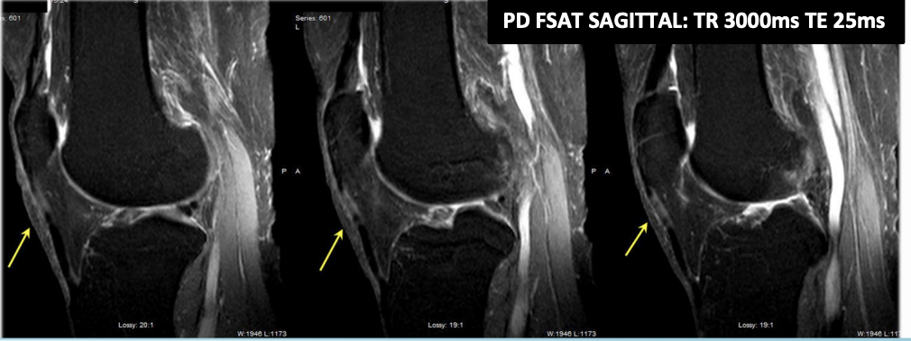
confirmation of magic angle artifact
confirmation of magic angle artifact, instead of tendinopathy, is made by the utilization of a long TE sequence, where the long T2 relaxation time of the collagen fibers will not yield high signal in the tendon at the 55° angle to the magnet.
annefact or cusp artifacts come from
active RF coil channels or elements outside the scanning field of view
annefact artifacts happen in what imaging
spine