PSAD LOOKSFAM (MERGED QUIZZES) FINAL
1/242
There's no tags or description
Looks like no tags are added yet.
Name | Mastery | Learn | Test | Matching | Spaced |
|---|
No study sessions yet.
243 Terms
a
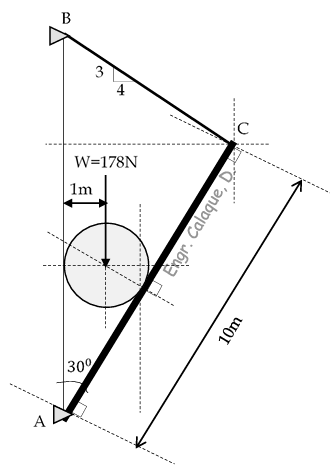
1. In the figure shown, Find the tension in chord BC
a) 134.572N
b) 205.782N
c) 202.981N
d) 358.000N
d
2. A cable weighing 20kg/m has a span of 150m and has a sag of 12m. Determine the length of the cable.
a) 105.56m
b) 128.35m
c) 139.09m
d) 152.53m
b
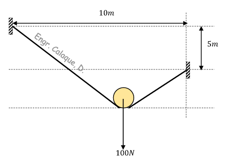
3. A smooth floating pulley supports a load of 100N as shown in the figure.
It is suspended on a 20m long string supported as shown. Find the tension in the string.
a) 35.05N
b) 57.74N
c) 80.03N
d) 44.95N
a
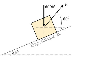
Situation 01: The static and kinetic coefficient of friction between the block and the plane are 0.25 and 0.20, respectively.
Determine the following: 4. Smallest value of P to start the block up the plane
a) 461.500N
b) 296.450N
c) 446.500N
d) 302.776N
c
Situation 01: The static and kinetic coefficient of friction between the block and the plane are 0.25 and 0.20, respectively.
5. Smallest value of P to keep it moving up
a) 461.500N
b) 296.450N
c) 446.500N
d) 302.776N

a
Situation 01: The static and kinetic coefficient of friction between the block and the plane are 0.25 and 0.20, respectively.
6. Smallest value of P to keep the block from moving down.
a) 276.370N
b) 106.780N
c) 374.694N
d) 177.455N

d
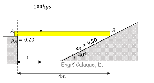
Situation 02: The uniform 50kgs plank is resting on rough surfaces at A and B. The coefficient of friction is shown in the figure below. If a 100kgs man starts walking from A toward B.
Compute the reaction at A when the block starts to slide
a) 505.65N
b) 689.44N
c) 703.06N
d) 816.788N

b
Situation 02: The uniform 50kgs plank is resting on rough surfaces at A and B. The coefficient of friction is shown in the figure below. If a 100kgs man starts walking from A toward B.
8. Compute the reaction at B when the block starts to slide
a) 505.65N
b) 689.44N
c) 703.06N
d) 816.788N
b
Situation 03: A motorist is travelling at 70kph when he sees a traffic light in an intersection 250m ahead turn red. The light’s red cycle is 15seconds. The motorist wants to enter the intersection without stopping his vehicle, just as the light turns green.
10. What uniform deceleration of the vehicle will just put the motorist in the intersection when the light turns green?
a) -0.25m/s^2
b) – 0.37m/s^2
c) – 0.42m/s^2
d) -0.55m/s^2
b
Situation 03: A motorist is travelling at 70kph when he sees a traffic light in an intersection 250m ahead turn red. The light’s red cycle is 15seconds. The motorist wants to enter the intersection without stopping his vehicle, just as the light turns green.
11. If the vehicle decelerates at a constant rate of 0.5m/s^2, what will be its speed when the light turns green?
a) 39.894kph
b) 42.984kph
c) 50.341kph
d) 60.004kph
a
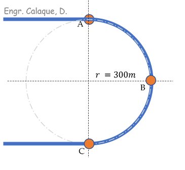
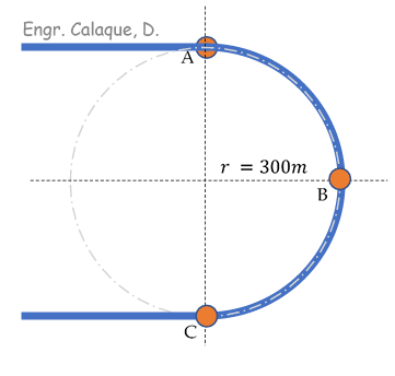
Situation 04: A car enters point A of the semi-circular track shown at 120kph and leaves point C at 180kph.
If it gains speed at uniform rate, and the radius of track is 300m, find the following:
12. Velocity of car at B
a) 42.491m/s
b) 32.560m/s
c) 22.648m/s
d)52.056m/s
a
Situation 02: The uniform 50kgs plank is resting on rough surfaces at A and B. The coefficient of friction is shown in the figure below. If a 100kgs man starts walking from A toward B.
9. Compute the distance x when the block starts to slide.
a) 1.73m
b) 2.05m
c) 1.12m
d) 3.32m
b
Situation 04: A car enters point A of the semi-circular track shown at 120kph and leaves point C at 180kph.
If it gains speed at uniform rate, and the radius of track is 300m, find the following:
13. Acceleration of the car as it passes point B
a) 5.1m/s^2
b) 6.1m/s^2
c) 7.1m/s^2
d) 4.1m/s^2
c
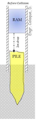
Situation 05: The ram of a pile driver has a mass of 800kgs and is released from rest 2m above the top of the 2400kgs pile as shown. If the ram rebounds to a height of 0.1m immediately after impact with the pile.
14. Compute the velocity of the pile after the impact
a) 1.4m/s
b) 6.26m/s
c) 2.55m/s
d) 0.5m/s
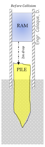
c
Situation 05: The ram of a pile driver has a mass of 800kgs and is released from rest 2m above the top of the 2400kgs pile as shown. If the ram rebounds to a height of 0.1m immediately after impact with the pile.
b
The simple truss shown supports the two loads, each of magnitude L = 10KN.
Determine the force in member CD.
a) 14.17KN
b) 16.17KN
c) 6.46KN
d) 6.01KN
b
02. A steel plate of dimensions 2.5 x 1.2 x 0.1m is hoisted by a cable sling that has a clevis at each end (see figure). The pins through the clevis are 18mm in diameter and are located 2m apart. Each half of the cable is at an angle of 32degrees to the vertical.
For these conditions, determine the average bearing stress between the steel plate and the pins.
a) 26.76MPa
b) 7.57MPa
c) 13.62MPa
d) 23.10MPa
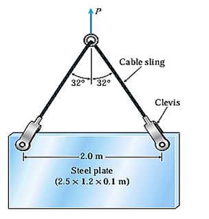
c
03. A uniform concrete slab of mass “m” is to be attached as shown in the figure, to two rods whose lower ends are initially at the same level. Determine the ratio of the areas of the rods so that the slab will remain level after it is attached to the rods.
a) 1/60
b) 5/60
c) 7/60
d) 9/60
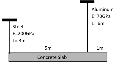
d
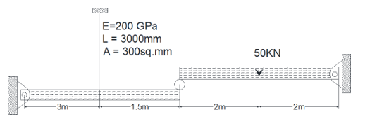
04. A steel rod at B helps support a load of 50KN. The rigid bars shown in the figure are separated by a roller at C and pinned at A and D. Compute the vertical displacement of roller at point C.
a) 5.8125mm
b) 4.8125mm
c) 3.8125mm
d) 2.8125 mm
b
05. A steel wire 30ft long hanging vertically supports a load of 500lbs. Neglecting the weight of wire, determine the required diameter if the stress is not to exceed 20ksi and total elongation is not to exceed 0.20in. Assume E = 29x10^6psi.
a) 0.1784in
b) 0.1988in
c) 0.2784in
d) 0.2988in
d
06. A reinforced concrete column, 5m high has a cross-section of 400mm x 400mm. It is reinforced by 4 steel bars each 20mm in diameter and carries a load of 1000KN. Young’s modulus for steel is 200,000MPa and that for concrete is 15,000MPa. Neglecting concrete displaced or concrete holes. Determine the shortening of column.
a) 1.24mm
b) 1.08mm
c) 1.56mm
d) 1.89mm
a
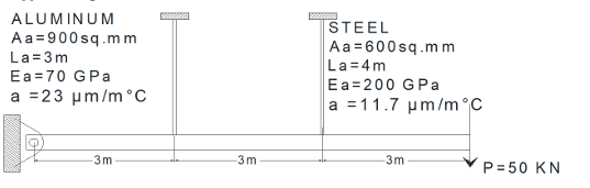
07: For the assembly as shown, determine the stress of the aluminum rod if the temperature rises up to 400C after the load P= 50KN is applied. Neglect the deformation and the mass of the horizontal bar AB.
a) 11.40MPa
b) 133.55MPa
c) 22.56MPa
d) 152.44MPa
c
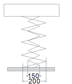
08. As shown in the figure, a homogeneous 50kg rigid block is suspended by the three springs whose lower ends were originally at the same level. Each steel spring has 24 turns of 10mm diameter wire on a mean diameter of 100mm and G=83 GPa. The bronze spring has 48 turns of 20mm diameter wire on a mean diameter of 150mm and G= 42GPa. Compute the maximum shearing stress in each spring.
a) 5.06MPa, 10.6MPa and 38.72MPa
b) 7.87MPa, 20.1MPa and 38.72MPa
c) 9.93MPa, 40.3MPa and 38.72MPa
d) 6.71MPa, 30.8MPa and 38.72MPa
c
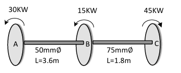
09. The compound shaft known rotates at 3 rps with 30KW taken off at A, 15KW off at B, and 45KW applied at C. If G = 83GPa, determine the maximum stress.
a) 54.85MPa
b) 18.82MPa
c) 64.85MPa
d) 28.82MPa
b
10. A load P is supported by two concentric steel springs arranged as shown. The inner spring consists of 30 turns of 20mm diameter wire on a mean diameter of 150mm, the outer spring has 20 turns of 30mm wire on a mean diameter of 200mm.Compute the maximum load that will not exceed a shearing stress of 140 MPa in either spring. Use G= 83 GPa.
a) 2749N
b) 9055N
c) 6904N
d) 2151N
a
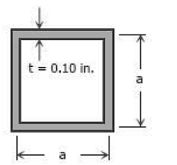
11. A torque of 450 lb-ft is applied to the square section shown in the figure. Determine the stress on the thin-walled tube if 𝑡 = 0.1 𝑎𝑛𝑑 𝑎 = 2.12 𝑖𝑛.
a) 6077psi
b) 5077psi
c) 4077psi
d) 3077psi
c
12. A flanged bolt coupling consists of six 10 mm diameter steel bolts on a bolt circle 300mm in diameter and four 10 mm diameter steel bolts on a concentric bolt circle 200mm in diameter, what torque can be applied without exceeding the shearing stress of 60MPa in the bolts?
a) 3.497 KN-m
b) 4.497 KN-m
c) 5.497 KN-m
d) 6.497 KN-m
b
a) (59.52MPa,58.16MPa)
b) (23.01MPa, 6.31MPa)
c) (7.32MPa, 10MPa)
d) (27.32MPa, 10MPa)
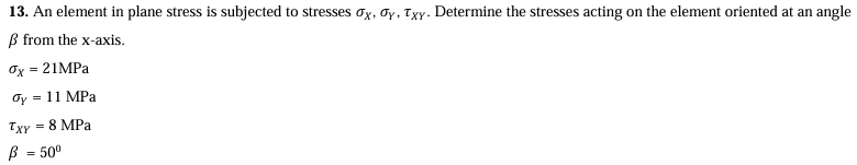
d
a) 12.83KN-m
b) 13.83KN-m
c) 14.83KN-m
d) 15.83KN-m
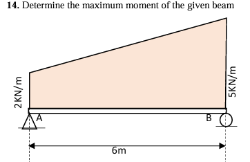
a
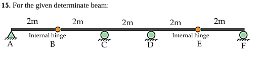
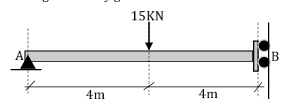
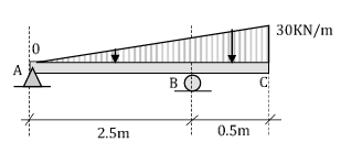
Determine the length of the beam where uniform load can produce maximum negative moment 5m from support A.
a) 8m
b) 2m
c) 5m
d) 10m
a
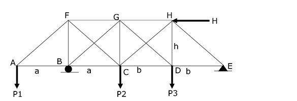
SITUATION 01: For the plane truss shown in the figure, diagonal members CF, BG, DG and CH are cables. 01. If P1 = 1.5KN, P2 = 0KN, P3 = 0KN, and H = 1KN, a = 3m, b = 2.25m, h = 3m, determine the force in member GD?
a) 1250N
b) 1000N
c) 1500N
d) 0N

d
SITUATION 01: For the plane truss shown in the figure, diagonal members CF, BG, DG and CH are cables. 01. If P1 = 1.5KN, P2 = 0KN, P3 = 0KN, and H = 1KN, a = 3m, b = 2.25m, h = 3m, determine the force in member GD?
02. If P1 = 0, P2 = 3KN, P3 = 3KN, and H= 1.5KN, a = 3m, b = 2.25m and h = 3m, determine the force in member CF.
a) 2330N
b) 3800N
c) 3300N
d) 4670N
c
SITUATION 01: For the plane truss shown in the figure, diagonal members CF, BG, DG and CH are cables. 01. If P1 = 1.5KN, P2 = 0KN, P3 = 0KN, and H = 1KN, a = 3m, b = 2.25m, h = 3m, determine the force in member GD?
03. If P1 = 1KN, P2 = 3KN, P3 = 3KN, and H= 1.5KN, a = 3m, b = 2.25m and h = 3m, determine the force in member DH.
a) 2150N
b) 2500N
c) 2300N
d) 3250N
d
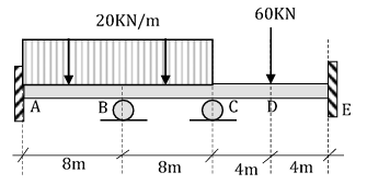
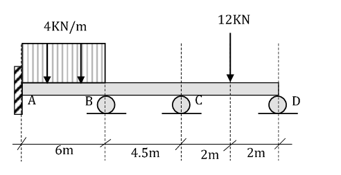
04. A continuous beam shown carries a uniform load of 20KN/m from A to C and a concentrated load of 60KN at D. Assume EI constant. Which of the following gives the reaction at B?
a) 103.5KN
b) 112.9KN
c) 84.9KN
d) 164.7KN
d
05. Determine the deflection at point C of the given beam below. Take EI as constant
a) 2296.5/EI
b) 9626.5/EI
c) 2962.5/EI
d) 6962.5/EI
a
06. Which of the following structures is statically determinate both externally and internally?
b
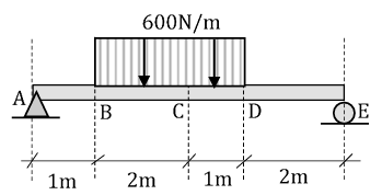
07. The beam is subjected to the loading shown. Which of the following gives the moment at C.
a) -15.304 KN-m
b) -2.872 KN-m
c) -5.339 KN-m
d) -6.001 KN-m
c
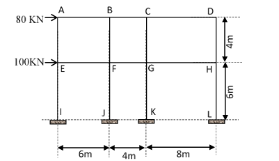
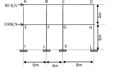
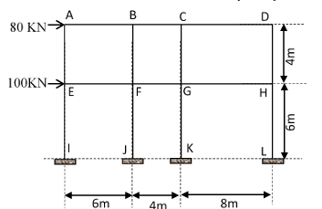
Situation 02: The structural framing plan for a proposed second story apartment building is subjected to a nodal lateral load of 80KN and 100KN at second floor and first floor, respectively as shown in the figure below. If the cross-sectional areas of the columns are the same, determine the following:
08. Shear force on member EF using portal method
a) 29.165KN
b) 58.34KN
c) 38.89KN
d) 18.253KN
d
Situation 02: The structural framing plan for a proposed second story apartment building is subjected to a nodal lateral load of 80KN and 100KN at second floor and first floor, respectively as shown in the figure below. If the cross-sectional areas of the columns are the same, determine the following:
09. Axial force on member HL using cantilever method
a) 47.78KN
b) 7.54KN
c) 2.34KN
d) 42.75KN
b
Situation 02: The structural framing plan for a proposed second story apartment building is subjected to a nodal lateral load of 80KN and 100KN at second floor and first floor, respectively as shown in the figure below. If the cross-sectional areas of the columns are the same, determine the following:
10. Moment on support K using cantilever method
a) 80.55 KN-m
b) 189.48 KN-m
c) 150.03 KN-m
d) 120 KN-m
a
11.The beam AB has a built-in support at A. The roller support at B allows vertical deflection but prevents rotation. Which of the following most nearly gives the deflection at B. Take EI as constant.
a) 320/EI
b) 640/EI
c) 960/EI
d) 2560/EI
a
c
13. A propped beam having a span of 20m carries a triangular load which varies from 10KN/m at the fixed end to zero at the other support. Compute the maximum deflection of the beam. Hint: Calculate the reaction at the propped end first.
a) 2831/EI
b) 8231/EI
c) 3812/EI
d) 1831/EI
a
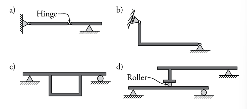
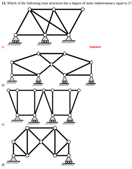
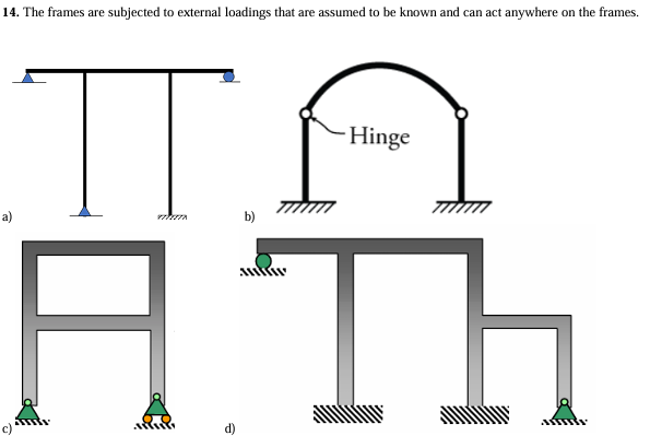
Which of the following statements about the given frame structures is accurate?
I. Figure (a) has a static indeterminacy of 5 degrees.
II. Figure (b) has a static indeterminacy of 2 degrees.
III. Figure (c) has a static indeterminacy of 6 degrees.
IV. Figure (d) has a static indeterminacy of 9 degrees.
a) I only
b) I and III only
c) II and IV only
d) All of the above
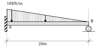
15. For the beam that is loaded as shown in the figure below, the deflection at the free end of the beam is most nearly equal to:
a) 18.25/EI
b) 21.02/EI
c) 2.77/EI
d) 1.22/EI
b
1. Determine the balanced eccentricity
a) 220.686mm
b) 216.797mm
c) 210.661mm
d) 200.431mm

d
2. Determine the location of the neutral axis to achieve a pure flexure condition.
a) 111.724mm
b) 70.875mm
c) 140.433mm
d) 70.521mm
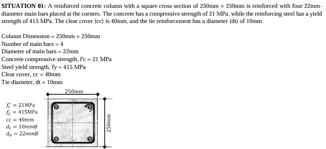
b
SITUATION 02: A rectangular concrete beam has a width of 250mm and a total depth of 450mm. It is reinforced with a total steel area of 1875 sq.mm effective depth of 375mm. fc’ = 27.6MPa, fy = 414.7MPa.
3) Which of the following most nearly gives the depth of compression block?
a) 176.56mm
b) 132.58mm
c) 225.67mm
d) 220.61mm
c
SITUATION 02: A rectangular concrete beam has a width of 250mm and a total depth of 450mm. It is reinforced with a total steel area of 1875 sq.mm placed at an effective depth of 375mm. fc’ = 27.6MPa, fy = 414.7MPa
4) Which of the following most nearly gives the moment capacity reduction factor?
a) 0.900
b) 0.751
c) 0.834
d) 0.882
a
SITUATION 02: A rectangular concrete beam has a width of 250mm and a total depth of 450mm. It is reinforced with a total steel area of 1875sq.mm placed at an effective depth of 375mm. fc’ = 27.6MPa, fy = 414.7MPa
5) Which of the following most nearly gives the factored moment capacity of the beam?
a) 200.20KN-m
b) 210.65KN-m
c) 150.88KN-m
d) 300.51KN-m
c
6. A concrete T- beam having a flange width = 550mm, flange thickness = 100mm, web width = 300mm, d’ = 60mm (compression bars) and effective depth = 450mm (measured from the topmost fiber of the slab to the centroid of the tension bars) is shown below.
Take fc’ = 21MPa and fy = 345MPa. Use 2010/2015 NSCP Code provisions. Analyze as doubly reinforced beam, determine the ultimate moment capacity of the given T-Beam, ∅𝑀𝑛.
a) 356.871 KN − m
b) 590.055 KN −m
c) 452.683 KN - m
d) 600.232 KN −m
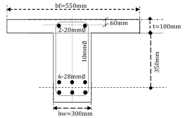
b
depth of 625mm. The beam supports a total factored load of 168KN/m which includes the weight of the beam. fc’ = 27.6MPa, fy = 414MPa. Use normal weight of concrete with 𝜆 = 1.0
7) Determine the location from the face of the support where the 10mm stirrups will be stopped.
a) 1.50m
b) 2.50m
c) 2.25m
d) 1.65m
a
SITUATION 03: A simply supported rectangular concrete beam has a clear span of 6m has a width of 400mm and has an effective depth of 625mm. The beam supports a total factored load of 168KN/m which includes the weight of the beam. fc’ = 27.6MPa, fy = 414MPa. Use normal weight of concrete with 𝜆 = 1.0
8) Determine the spacing requirement at the critical section based on the required 𝜙𝑉𝑐 where the stirrups will be most closely spaced.
a) 130mm O.C
b) 300mm O.C
c) 460mm O.C
d) 150mm O.C
a
SITUATION 03: A simply supported rectangular concrete beam has a clear span of 6m has a width of 400mm and has an effective depth of 625mm. The beam supports a total factored load of 168KN/m which includes the weight of the beam. fc’ = 27.6MPa, fy = 414MPa. Use normal weight of concrete with 𝜆 = 1.0
9) Determine approximately the total number of stirrups needed for the entire beam.
a) 26stirrups
b) 30stirrups
c) 46 stirrups
d) 20stirrups
b
SITUATION 04: A rectangular concrete beam has a simple span of 7.2m which carries a dead load of 23.5KN/m and a live load of 16KN/m. It has a width of 400mm and a clear cover of 50mm. fc’ = 30MPa, fy = 400MPa, steel ratio = 0.008. Use capacity reduction factor = 0.90
10) Which of the following most nearly gives the effective depth of the beam?
a) 568.5mm
b) 587.5mm
c) 642.5mm
d) 655.5mm
b
SITUATION 04: A rectangular concrete beam has a simple span of 7.2m which carries a dead load of 23.5KN/m and a live load of 16KN/m. It has a width of 400mm and a clear cover of 50mm. fc’ = 30MPa, fy = 400MPa, steel ratio = 0.008. Use capacity reduction factor = 0.90
11) Which of the following most nearly gives the number of 25mm diameter bars needed for tension reinforcement.
a) 2pcs
b) 4pcs
c) 6pcs
d) 5pcs
b
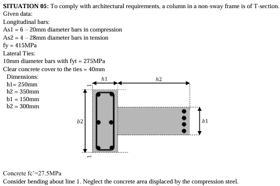
12. Which of the following gives the location of the plastic centroid of the section from the line 1 along the x-axis? For all bars, fs = fy
a) 249mm
b) 292mm
c) 294mm
d) 229mm
a
13) If the T-section is reinforced such that the plastic centroid of the section falls at 280mm from the line 1 along the x-axis, determine the bending moment Mu, induced by a factored load Pu = 3200KN acting along x-axis at 400mm from line 1.
a) 384KN-m
b) 352KN-m
c) 346KN-m
d) 484KN-m

c
SITUATION 06: A rectangular beam reinforced for both tension and compression bars has an area of 1250mm^2 for compression bars and 4032 sq.mm for tension bars. The tension bars are placed at a distance of 75mm from the bottom of the beam while the compression bars are placed 62.5mm from the top of the beam. f’c = 20.7MPa, fy = 414.6MPa. Width of beam is 350mm with a total depth of 675mm.
14. Which of the following most nearly gives the ultimate moment capacity of the beam?
a)555.5 KN-m
b) 666.6 KN-m
c) 777.7 KN-m
d)888.8 KN-m
a
SITUATION 06: A rectangular beam reinforced for both tension and compression bars has an area of 1250mm^2 for compression bars and 4032 sq.mm for tension bars. The tension bars are placed at a distance of 75mm from the bottom of the beam while the compression bars are placed 62.5mm from the top of the beam. f’c = 20.7MPa, fy = 414.6MPa. Width of beam is 350mm with a total depth of 675mm.
15. Which of the following most nearly gives the safe live concentrated load that the beam could support at its midspan if it has a span of 6m. Assume weight of concrete to be 23.5KN/m^3? Use 1.4D + 1.7L
a) 29.127KN
b) 20.413KN
c) 24.770KN
d) 33.484KN
c
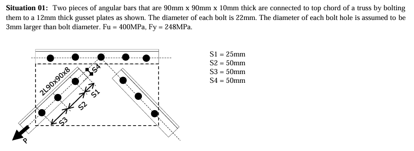
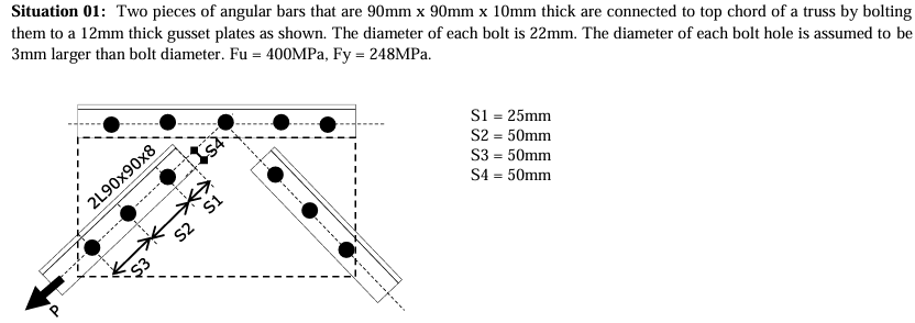
01. Which of the following gives the maximum value of P so that the allowable shearing stress of 0.3Fu in bolts will not be exceeded.
a) 210.8KN
b) 273.7KN
c) 136.8KN
d) 118.2KN
b
02. Which of the following gives the maximum value of P so that the allowable bearing stress of 1.2Fu is not exceeded.
a) 750.1KN
b) 380.1KN
c) 213.2KN
d) 532.3KN
b
03. Which of the following gives the maximum value of P considering block shear? Using allowable stresses of 0.4Fy for shear and 0.6Fy for tension.
a) 450KN
b) 117KN
c) 324KN
d) 143KN

b
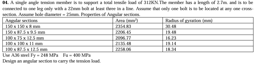
a) 100 x 75 x 12.5 mm
b) 100 x 100 x 11 mm
c) 150 x 150 x 8 mm
d) 100 x 87.5 x 12.5 mm
d
Situation 02: A civil engineer is task to design for foundation plan for a 3- story commercial building. After doing the structural analysis of the structure, he found out that the critical footing is subjected to total axial dead loads of 1400KN including column’s weight, total axial live loads of 1850KN, total bending moment caused by dead loads of 350KNm and a total bending moment caused by live loads of 220KN/m. He proposed to use a 760mm thick rectangular footing whose width limited to 3600mm due to the restriction of property line. The base of the footing is 1.8m in depth from the natural ground surface. The unit weight of soil and concrete is 16.8 KN/m3 and 24KN/m3, respectively. Use f'c= 34MPa, fy= 276MPa, dBAR = 28mm diameter, steel cover = 75mm (minimum cover based on NSCP). If the allowable soil bearing pressure is 240KPa and effective depth by top bar (dTOP) is to be used for both shear (wide beam and punching shear) and bending, design a rectangular footing by calculating the following requirements:
05. Actual wide beam shear along the longer direction
a) 1067.67KN
b) 1567.05KN
c) 1309.89KN
d) 1857.75kN
c
Situation 02: A civil engineer is task to design for foundation plan for a 3- story commercial building. After doing the structural analysis of the structure, he found out that the critical footing is subjected to total axial dead loads of 1400KN including column’s weight, total axial live loads of 1850KN, total bending moment caused by dead loads of 350KNm and a total bending moment caused by live loads of 220KN/m. He proposed to use a 760mm thick rectangular footing whose width limited to 3600mm due to the restriction of property line. The base of the footing is 1.8m in depth from the natural ground surface. The unit weight of soil and concrete is 16.8 KN/m3 and 24KN/m3, respectively. Use f'c= 34MPa, fy= 276MPa, dBAR = 28mm diameter, steel cover = 75mm (minimum cover based on NSCP). If the allowable soil bearing pressure is 240KPa and effective depth by top bar (dTOP) is to be used for both shear (wide beam and punching shear) and bending, design a rectangular footing by calculating the following requirements:
06. Actual punching shear
a) 4067.23KN
b) 4167.89KN
c) 4691.66kN
d) 4506.78KN
a
07. Based on Weld Shear
a) 328KN
b) 205KN
c) 414KN
d) 589KN

c
08. Based on Block Shear
a) 328KN
b) 205KN
c) 414KN
d) 589KN
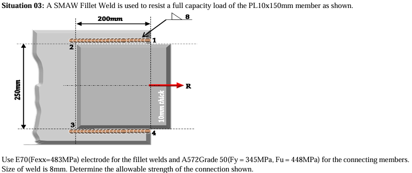
b
09. Find the maximum stress on bolt
a) 74.27MPa
b) 87.7MPa
c) 46.63MPa
d) 52.79MPa

d
10. If the allowable shear stress is 50MPa, determine the diameter of the bolt.
a) d≥ 15.22mm
b) d≥ 51.22mm
c) d≥ 12.22mm
d) d≥ 21.22mm
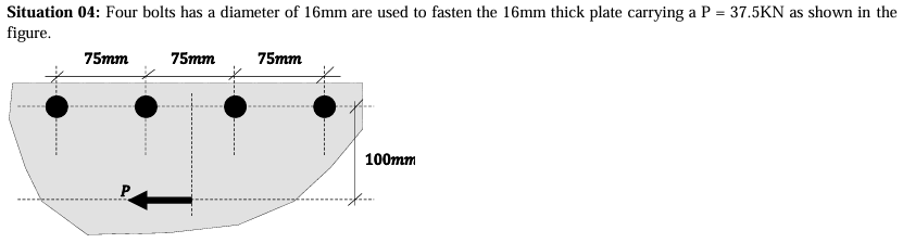
d
11. If it has a simple span of 3m
a) 126.81MPa
b) 148.8MPa
c) 78.84MPa
d) 163.68MPa
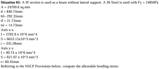
a
12. If it has a simple span of 6m
a) 126.81MPa
b) 148.8MPa
c) 78.84MPa
d) 163.68MPa

c
13. If it has a simple span of 9m
a) 126.68MPa
b) 148.8MPa
c) 78.84MPa
d) 163.68MPa

a
14. Calculate the required nominal wide beam shear stress at critical section.
a) 0.358MPa
b) 0.489MPa
c) 0.205MPa
d) 0.188MPa
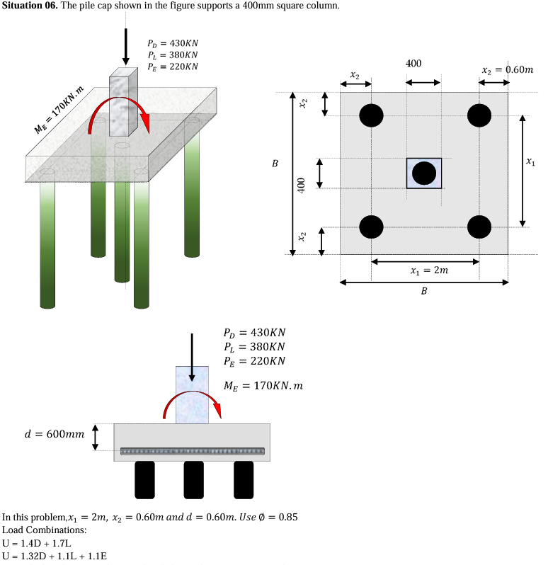
b
15. Calculate the required nominal punching shear stress at critical section.
a) 0.358MPa
b) 0.489MPa
c) 0.205MPa
d) 0.188MPa

A
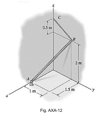
SITUATION 1: The smooth uniform rod AB in figure AXA-12 is supported by a ball-and-socket joint at A, the wall at B, and cable BC. If the rod has a mass of 20 kg, calculate:
1. Tension in BC, N.
A. 43.87
B. 58.86
C. 176.58
D. 191.22

B
SITUATION 1: The smooth uniform rod AB in figure AXA-12 is supported by a ball-and-socket joint at A, the wall at B, and cable BC. If the rod has a mass of 20 kg, calculate:
2. Normal force at B, N.
A. 43.87
B. 58.86
C. 176.58
D. 191.22
D
SITUATION 1: The smooth uniform rod AB in figure AXA-12 is supported by a ball-and-socket joint at A, the wall at B, and cable BC. If the rod has a mass of 20 kg, calculate:
3. Reaction at A, N.
A. 43.87
B. 58.86
C. 176.58
D. 191.22

C
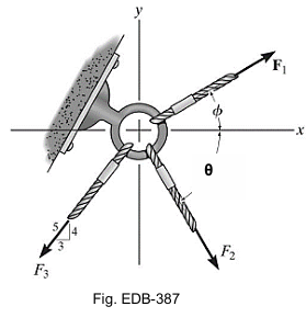
SITUATION 2: The eyebolt in figure EBD-387 is subjected to three (3) forces, F1, F2, and F3.
4. How much is the angle, theta (degrees), if the resultant of the three forces is 650 N and acts along the negative y axis? Given: F2 = 500 N; F3 = 450 N; Angle phi = 30°.
A. 21.45
B. 23.46
C. 20.56
D. 28.91
B
SITUATION 2: The eyebolt in figure EBD-387 is subjected to three (3) forces, F1, F2, and F3.
5. Determine the magnitude of the resultant force (N) acting on the eyebolt. Given: F1 = 600 N; F2 = 500 N; F3 = 450 N; Angle phi = 30°; Theta = 60°.
A. 657.8
B. 701.9
C. 765.2
D. 691.2

C
SITUATION 2: The eyebolt in figure EBD-387 is subjected to three (3) forces, F1, F2, and F3.
6. Determine the direction (degrees) of the resultant force acting on the eyebolt measured clockwise from the positive x-axis. Given: F1 = 600 N; F2 = 500 N; F3 = 450 N; Angle phi = 30°; Theta = 60°.
A. 36.4
B. 38.1
C. 44.6
D. 48.1

A
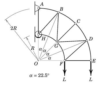
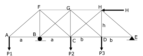
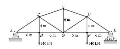
SITUATION 3: A truss is loaded as shown. The working stresses are 140 MPa in tension and 100 MPa in compression. (The working stress in compression is smaller to reduce the danger of buckling.)
7. Calculate the smallest safe cross-sectional area of member CD, in mm2.
A. 1476
B. 1500
C. 980
D. 841
B
SITUATION 3: A truss is loaded as shown. The working stresses are 140 MPa in tension and 100 MPa in compression. (The working stress in compression is smaller to reduce the danger of buckling.)
8. Calculate the smallest safe cross-sectional area of member GD, in mm2.
A. 1476
B. 1500
C. 980
D. 841

D
SITUATION 3: A truss is loaded as shown. The working stresses are 140 MPa in tension and 100 MPa in compression. (The working stress in compression is smaller to reduce the danger of buckling.)
9. Calculate the smallest safe cross-sectional area of member GF, in mm2.
A. 1476
B. 1500
C. 980
D. 841

C
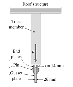
SITUATION 4: Truss members supporting a roof are connected to a 26-mm-thick gusset plate by a 22 mm diameter pin as shown in the figure. The two end plates on the truss members are each 14 mm thick.
10. If the load P = 80 kN, what is the largest bearing stress (MPa) acting on the pin?
A. 130
B. 135
C. 140
D. 145
A
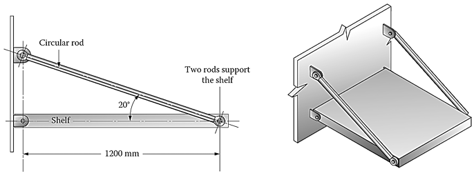
SITUATION 1: A shelf is being designed to hold crates having a total mass of 2025 kg. Two support steel rods in the figure will hold the shelf. Assume that the center of gravity of the crates is at the middle of the shelf and the shelf is rigid. Neglect the weight of the shelf and the rods.
1. Calculate the minimum required diameter (mm) of the rod if the stress is limited to 110 MPa.
A. 12.97
B. 14.56
C. 16.22
D. 13.45
A
SITUATION 1: A shelf is being designed to hold crates having a total mass of 2025 kg. Two support steel rods in the figure will hold the shelf. Assume that the center of gravity of the crates is at the middle of the shelf and the shelf is rigid. Neglect the weight of the shelf and the rods.
2. If the diameter of the rods is 25 mm, calculate the vertical displacement (mm) of the rod-shelf connection.
A. 0.552
B. 0.723
C. 0.892
D. 1.104
B
3. If the diameter of the rods is 25 mm, calculate the horizontal displacement (mm) of the rod-shelf connection.
A. 0.354
B. 0.177
C. 0.289
D. 0.223
D
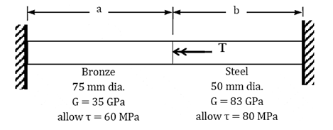
SITUATION 2: The shaft shown is made of bronze and steel and is fixed at both ends. It is subjected to a concentrated torsional moment at the junction.
4. Find the ratio of the length of steel segment to the length of the bronze segment such that the allowable stress in each material is reached simultaneously.
A. 0.225
B. 0.568
C. 0.891
D. 1.186

B
SITUATION 2: The shaft shown is made of bronze and steel and is fixed at both ends. It is subjected to a concentrated torsional moment at the junction.
5. Determine the maximum torque (kN-m) that can be applied at the junction of the two segments if a = 2 m and b = 1.5 m.
A. 3.45
B. 5.10
C. 4.45
D. 6.81

C
SITUATION 2: The shaft shown is made of bronze and steel and is fixed at both ends. It is subjected to a concentrated torsional moment at the junction.
6. If T = 4.5 kN-m, a = 2 m, and b = 1.5 m, calculate the rotation (in degrees) of the junction with respect to one end.
A. 1.56
B. 1.89
C. 2.92
D. 3.66
C
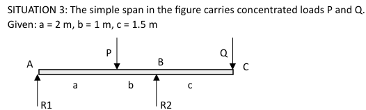
7. If P = 9 kN, what value of Q (kN) should be applied at the free end to prevent deflection at C?
A. 2.31
B. 1.87
C. 2.22
D. 1.95

C
8. If Q = 8.5 kN, what value of P (kN) should be applied to prevent deflection at C?
A. 32.1
B. 16.8
C. 34.4
D. 19.5
C
9. If the deflection at the free end is 7 mm downwards, what should be the equal values of the two concentrated loads (kN)? Use flexural rigidity = 24 x 1012 N-mm2.
A. 40.72
B. 43.28
C. 66.10
D. 68.40

D
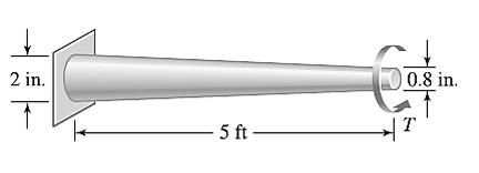
10. The tapered, wrought iron shaft carries the torque T = 2000 lb-in at its free end. Determine the angle of twist (degrees) of the shaft. Use G = 10 x 106 psi for wrought iron.
A. 2.12
B. 2.98
C. 1.56
D. 3.56
A
SITUATION 1: A 12-meter-long precast pile segment is to be lifted from a trailer down to the ground and then set in place prior to driving by a crane.
1. If two slings are to be used in lifting the pile to the ground, at what distance from the ends must the slings be placed for minimum bending due to its own weight?
A. 2.48 m
B. 3.00 m
C. 3.51 m
D. 7.03 m
A
SITUATION 1: A 12-meter-long precast pile segment is to be lifted from a trailer down to the ground and then set in place prior to driving by a crane.
2. At what distance from the ends must the slings be placed for minimum shear due to its own weight?
A. 3.00 m
B. 1.66 m
C. 4.34 m
D. 3.51 m
D
SITUATION 1: A 12-meter-long precast pile segment is to be lifted from a trailer down to the ground and then set in place prior to driving by a crane.
2. At what distance from the ends must the slings be placed for minimum shear due to its own weight?
A. 3.00 m
B. 1.66 m
C. 4.34 m
D. 3.51 m
C
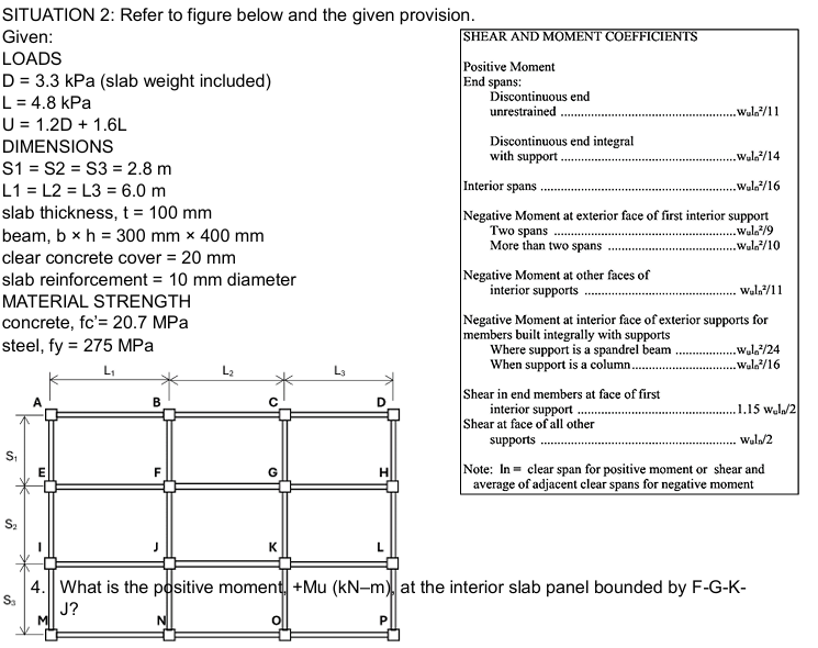
4. What is the positive moment, +Mu (kN–m), at the interior slab panel bounded by F-G-K J?
A. 3.0
B. 3.8
C. 4.6
D. 5.7

D
5. What is the required theoretical spacing (mm) of 10mm diameter bars for the positive moment Mu for slab panel bounded by F-G-K-J?
A. 150
B. 200
C. 250
D. 300