Electronics 245 - Week 4 - Lecture 9 - 2.1.3 to 2.1.5- Rectifier circuits, filters, detectors and voltage doublers
 Call Kai
 Learn
Learn Practice Test
 Spaced Repetition
 Match
Match Flashcards
 Knowt Play
1/8

There's no tags or description
Looks like no tags are added yet.
Name | Mastery | Learn | Test | Matching | Spaced | Call with Kai | Chat |
|---|
No analytics yet
Send a link to your students to track their progress
9 Terms
Define half-wave rectification
Draw a graph
A circuit will have a diode and output voltage is only in one direction
Voltage in then opposite direction is zero

Describe how to obtain full-wave rectification from a half-wave rectifier:
Draw the graph of output voltage
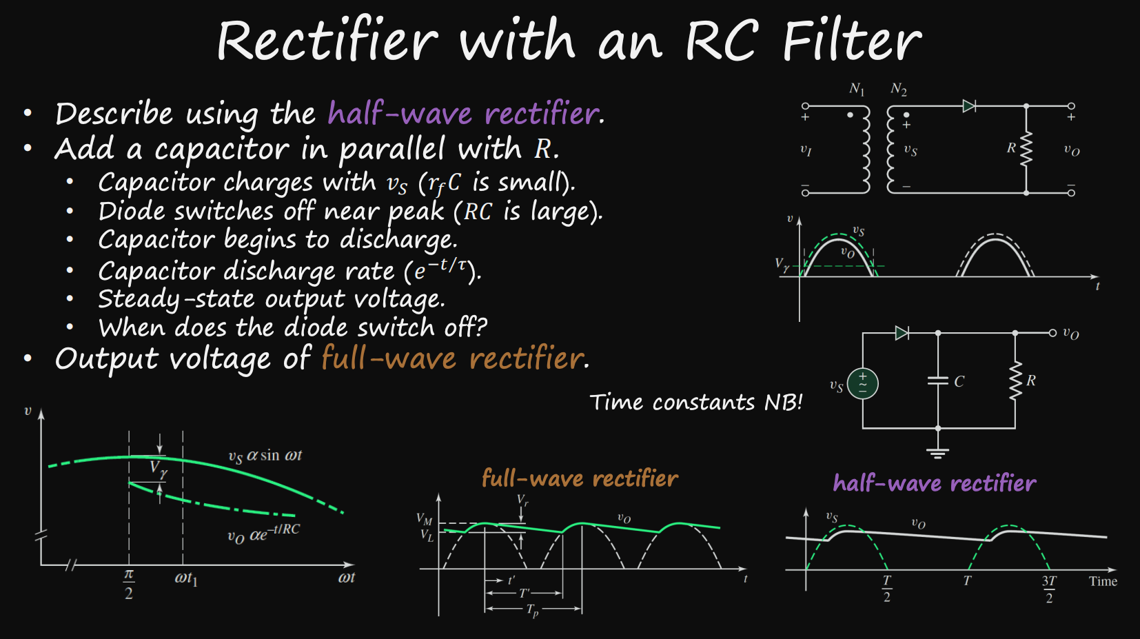
Define ripple voltage
The voltage that remains after rectification
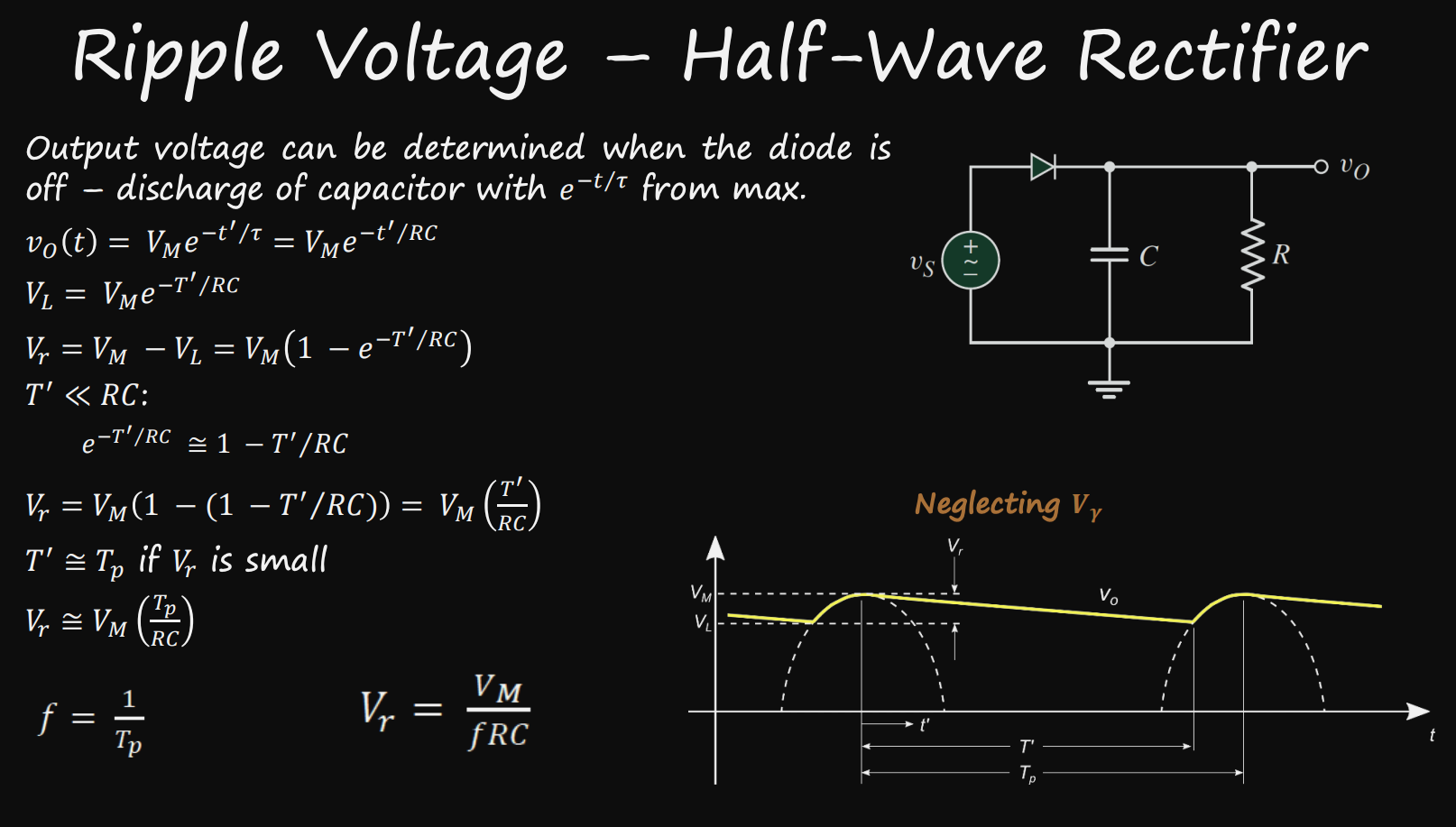
Derive the formula for Ripple voltage
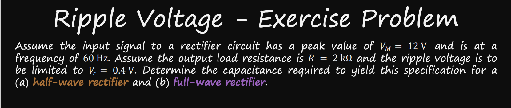
Solve

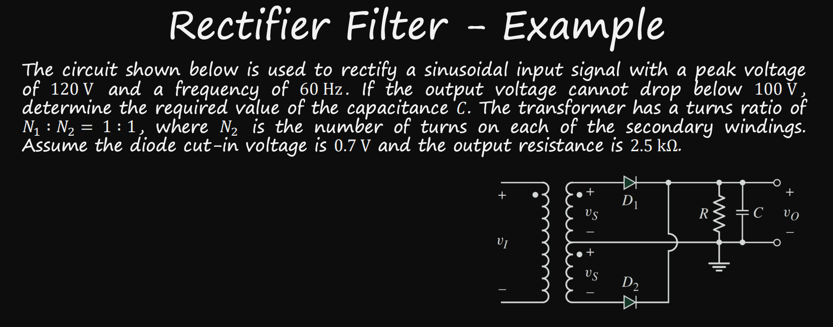
Solve
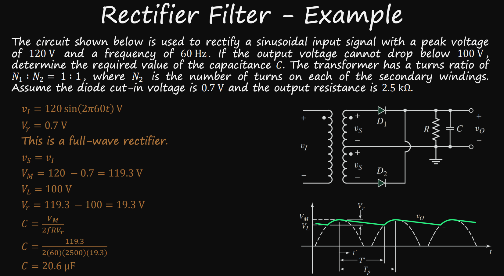
For a half and full wave rectifier:
Derive the equations for peak current passing through the diode
Derive the equations for average current passing through the diode

Describe the detector circuit:
Define it
Draw the circuit

Describe the Voltage Doubler:
What it is
Its uses
Conditions
Draw the circuit
