Introduction to computer Networks
1/83
There's no tags or description
Looks like no tags are added yet.
Name | Mastery | Learn | Test | Matching | Spaced | Call with Kai |
|---|
No analytics yet
Send a link to your students to track their progress
84 Terms
Computer Network
A computer network is a set o nodes connected by communication links.
Nodes
Can be a computer, printer or any other device capable of send/receiving data generated by other nodes in the network
Example for nodes
Computer
Server
Printer
Security camera
Many more (Switches, bridges, routers, etc)
Communication link
Wired link or wireless link
The link carries the information
Links
Wired; Cable
Wireless: air
End device
Starting point of communication
Computers
Network printers
VoIP Phones
Telepresence endpoint
Security cameras
Mobile handheld devices (Smart phones, tablets, PDAs, Wireless debit/credit card readers, barcode scanner)
Intermediary devices
The ones that connect end devices and allow data transmission on a network: hubs, switches, routers, gateways, firewalls or access points, call tower, modem, internet cloud
Forward data from one node to another
Switches
Wireless access point
Routers
Security Devices (Firewall)
Bridges
Hubs Repeaters
Cell Tower
Resource sharing
Computer network mainly used for resource sharing
Basic characteristics of computer network
Fault tolerance
Scalability
Quality of Service (QoS)
Security
Fault Tolerance
Ability to:
Continue working despite failures (takes another route)
Ensure no loss of service
Scalability
The ability to:
Grow based on the needs
Have good performance after growth
Ex) Network should work after adding 10 computers
Ex) The Internet
Quality of Service (QoS)
The ability to:
Set priorities
Manage data traffice to reduce data loss, delay etc
Ex) Delay of one second in email, delay in real time communication matters so router gives priority to VoIP phone than email
Ex) Router should know which data to prioritize
Security
The ability to prevent:
Unauthorized access
Misuse
Forgery
The ability to provide
Confidentiality
Integrity
Availability
Data Communication
Data communications are the exchange of data between two nodes via some form of link (transmission medium) such as a cable
Data Flow
Simplex
Half Duplex
Full Duplex
Simplex
Communication is always unidirectional
One device can transmit and the other device will receive
Example: Keyboards, Traditional monitors
Half Duplex
Communication is in both directions but not at the same time
If one device is sending, the other can only receive and vice versa
Example: Walkie-talkies
Duplex or Full Duplex
Communication is in both directions simultaneously
Device can send a receive at the same time
Example: Telephone line
Protocols
All communication schemes will have the following things in common
Source or sender
Destination or receiver
Channel or media
Rules or protocols govern all methods of communication
Protocol
Protocol = Rule
It is a set of rules that govern data communication
protocol determines:
What is communicated?
How it is communicated?
When it is communicated?
Protocols - Human Communicatoin
Protocols are necessary for human communication and include:
An identified sender and receiver
common language and grammar
speed and timing of delivery
Confirmation or acknowledgement requirements
Protocols - Network Communication
Protocols used in network communications also define:
Message encoding
Message formatting and encapsulation
Message timing
Message size
Message delivery options
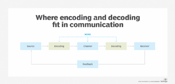
Message encoding
The source that is the source computer generates the message, gives it to encoder in order to generate signals, given to the transmitter and transmission medium, receiver, decoder (signal) understanding, message destination
Converting waves into signals
Message formatting and encapsulation
Agreed format.
Encapsulate the information (Source and information data) to identify the send and the receiver rightly
Message size
Humans break long messages into smaller parts or sentences. Long messages must also be broken into smaller pieces to travel across a network
Message timing
Flow control.
Response timeout.
Message Delivery Options
Unicast
One sender and one receiver
Multicast
Set of receiver but not to all
Broadcast
Sends data to all participants in the network
Peer-to-peer network
No Centralized administration
All peers are equal
Simple sharing applications
Not scalable
Client Server Network
Centralized administration
Request-Response model
Scalable
Server may be overloaded
Components of a Computer Network
Nodes, Media and Services
Nodes
End nodes (end devices)
Intermediary nodes
Media
Wired medium (guided medium)
Wireless medium (unguided medium)
Wired media
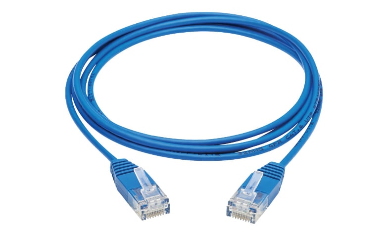
Ethernet straight through cable
Ethernet crossover cable
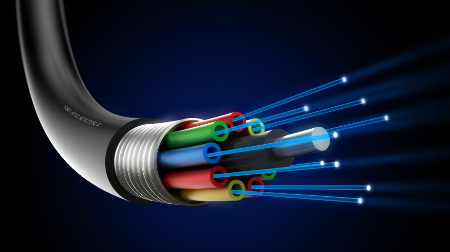
Fiber Optic cable
Coaxial cable
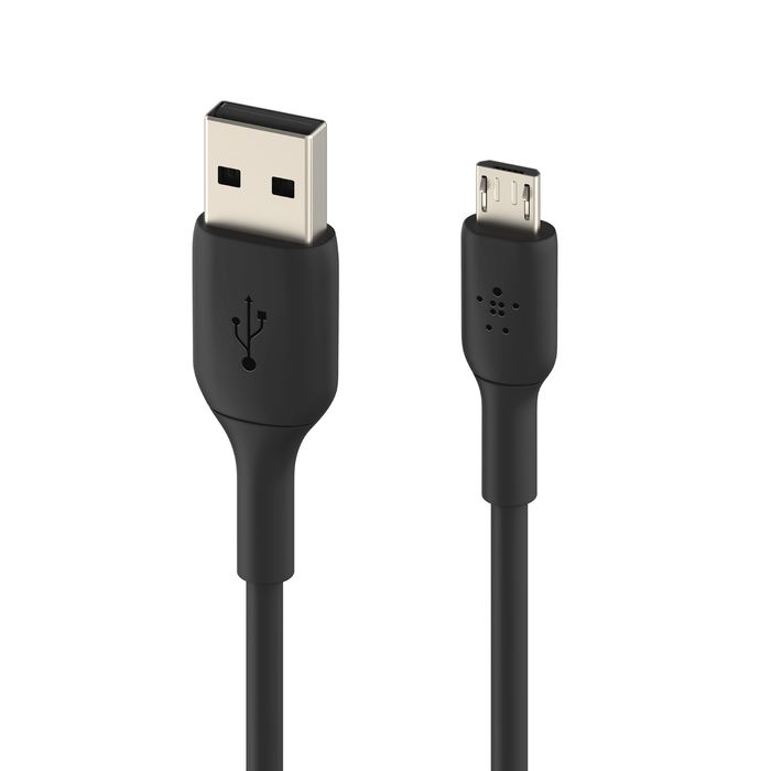
USB cableEt
Ethernet cable
Ethernet cross over cable
Two devices of same kind, two switches, two computers, two routers
Fiber Optic cables
Data carried in form of light waves, fastest mode of wired communication
Coaxial cable
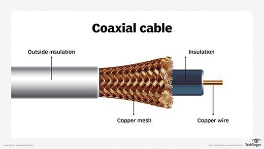 - Used for audio or video communication
Carries data in form of electric signals
USB Cables
Wireless Media
Infrared (example: short range communication - TV remote control)
Radio (Example: Bluetooth, Wi-Fi)
Microwaves (Example: Cellular System)
Satellite (Example: Long range communication - GPS)
Services
e-Mail
Storage services
File sharing
Instant messaging
Online game
Voice over IP
Video telephony
World Wide Web
Classification of Computer Networks
Local Area Network (LAN)
Metropolitan Area Network (MAN)
Wide Area Network (WAN)
Local Area Network (LAN)
A Local Area Network (LAN) is a computer network that interconnects computers within a limited are such as a residence, school, laboratory, university campus or office building
LAN Devices
Wired LAN (Ex: Ethernet - Hub, Switch)
Wireless LAN (Ex: Wi-FI)
Metropolitan Area Network (MAN)
A metropolitan area network (MAN) is a computer network that interconnects users with computer resources in a geographic region of the size of a metropolitan area (City)
MAN Devices
Switches/Hubs
Routers/Bridges
Wide Area Network (WAN)
A wide area network (WAN) is a telecommunications network that extends over a large geographical area for the primary purpose of computer networking
Communication at a large distance
WAN Devices
End devices and intermediary devices
The Internet
New trends
BYOD (Bring Your Own Device)
Online collaboration
Cloud computing
Cloud Computing
It is the on-demand availability of computer systems resources, especially data storage and computing power, without direct active management by the user
Network Topology
Arrangement of nodes of a computer network
Topology = layout
Physical Topology and Logical Topology
Physical topology - Placement of various nodes
Logical topology - Deals with the data flow in the network
Bus Topology
All data transmitted between nodes in the network is transmitted over the common transmission medium and is able to be received by all nodes in the network simultaneously
A signal containing the address of the intended receiving machine travels from a source machine in both directions to all machines connected to the bus until it finds the intended recipient
 Pros
ProsOnly one wire - less expensive
Suited for temporary network
Node failures does not affect others
Cons
Not fault tolerant (no redundancy) if transmission medium fails
Limited cable length
No security
Ring Topology
A ring topology is a bus topology in a closed loop
Peer to peer LAN topology
Two connections: one to each of its nearest neighbors
Unidirectional
Sending and receiving data takes place with the help of a TOKEN (TOKEN means nodes turn to send data,
 TOKEN circulated throughout circle)
Pros:
Performance better than Bus topology because it is in a closed loop
Can cause bottleneck due to weak links (a point of congestion in a production system that prevents it from functioning at full speed)
All nodes with equal access
Cons:
Unidirectional. Single point of failure will affect the whole network
high In load - low in performance
No security
Star Topology
Every node is connected to a central node called a hub or switch
Centralized management
All traffic must pass through the hub or switch
Pro:
Easy to desing and implement
Centralized administration
Scalable
Con:
Single point of failure affects the whole network
Bottlenecks due to overloaded switch/hub
Increased cost due to switch/hub
Mesh Topology
Each node is directly connected to every other nodes in the network
Fault tolerant and reliable
Pros:
Fault tolerant
Reliable
Cons:
Issues with broadcasting messages
Expensive and impractical for large networks
Hybrid Topology
IP Address
IP stands for Internet Protocol
Every node in the computer network is identified with the help of IP address
IP Address (IPV4)
Every node in the computer network is identified with the help of IP address
Logical address
Can change based on the location of the device
Assigned by manually or dynamically
Represented in decimal and it has 4 octets (x.x.x.x)
0.0.0.0 to 255.255.255.255 (32 bits)
MAC Address
MAC stands for Media Access Control
Every node in the LAN is identified with the help of MAC address
IP address = location of a person
MAC address = name of the person
routers need ip address
Switches need mac address
Physical address or hardware address
Unique
Cannot be changed
Assigned by the manufacturer
Represented in hexadecimal
Example: 70-20-84-00-ED-FC (48 bits)
Separator: hyphen ( -), period(.), and colon (:)
IP Address vvs MAC address
IP Address
Needed for communication
32 bit
Reprecented in decimal
Router needs IP address to forward data
Example: 10.10.23.56
MAC Address
Needed for comunication
48 bits
Represented in hexadecimal
Switch needs MAC address to forward data
Example: 70-20-84-00-ED-FC
Port addressing
Reaching our city = Reaching our network (IP adress)
Reaching our apartment = Reaching the host ( MAC address)
Reaching the right person = Reaching the right process (Port address)
Port Address or Port Number
In a node, many process will be running
Data which are sent/received must reach the right process
Every process in a node is uniquely identified using port numbers
Port = communication endpoint
Fixed port numbers and dynamic port numbers ( 0 - 65535)
Example:
Fixed port numbers: 25,80 etc,
OS assigned dynamic port numbers: 62414
Before sending the data, any node must
Attach source IP address and destination IP address
Attach source MAC address and destination MAC address
Attach source port number and destination port number
Switching
Switching in computer network helps in deciding the best route for data transmission if there are multiple paths in a larger network
One-to-one connection
Circuit switching
A dedicated path is established between the sender and receiver
Before data transfer, connection will be established ifrst
Ex: Telephone network
3 Phases in circuit switching
1. connection establishment
data transfer
connection disconnection
Message switching
Store and forward mechanism
message is transferred as a complete unit and forwarded using store and forward mechanism at the intermediary node
Broken into pieces, intermediary receives small pieces and forwards data
Not suited for streaming media and real-time applications
Packet switching
The internet is.a packet switched network
message is broken into individual chunks called as packets
Each packet is sent individually
Each packet will have source and destination IP address with sequence number
Sequence numbers will help the receiver to
Reorder the packets
Detect missing packets and
Send acknowledgments
Two approaches to packet swtiching
Datagram Approach
Virtual Circuit Approach
Packet switching - Datagram approach
Datagram packet switching is also known as connectionless switching
each indepdnent entity is called as datagram
Datagrams contain destination infroamtion and the intermediary devices uses this information to forward datagrams to right destination
In a datagram packet switching approach, the path is not fixed
Intermediate nodes take the routing decisions to forward the packets
Reorder done by the receiver
Packet switching - Virtual Circuit Approach
Virtual Circuit Switching is also known as connection-oriented switching
In the case of Virtual circuit switching, a preplanned route is established before the messages are sent
Call request and call accept packets are used to establisht he econnection between sender and receiver
In this approach, the path is fixed for the duration of a logical connection
Layering in Computer Networks
Layering means decomposing the problem into more manageable components (layers)
Pros;
It provides more modular design
Easy to troubleshoot
Protocols
It is a set of rules that governs data communication
The protocols in each layer governs the activities of the data communication
Layered Architectures
The OSI Reference Model
The TCP/IP Model
The OSI Model
OSI stands for Open System Interconnection
It is a model for understanding and designing a network architecture that is flexible, robust and interoperable
Developed by the international standards for organizations (ISO)
The OSI model is not a protocl
It is only a guideline and hence it is referred as OSI reference model
The OSI Model
Purpose of the OSI model is to show how to facilitate communication between different systems without requiring changes to the logic of the underlying hardware and software
The OSI model was never fully implemented
The TCP/IP Model
TCP/IP = Transmission Control Prtocol/Internet Protocol
The TCP/IP protocol suite was developed prior to the OSI model
Therefore, the layers in the TCP/IP protocol suite do not exactly match those in the OIS model
TCP/IP is a hierarchial protocol made up of interactive modules, each of which provides a specific functionality
One layer takes care of port addressing, mac addressing, ip addressing
Layers in OSI Reference Model
Application layer - Away
Presentation layer - Pizza
Session layer - Sausage
Transport layer - Throw
Network layer - Not
Data link layer - Do
Physical layer - Please
(Don’t want any intermediate node to access application data; focus on network data link and physical)
Application Layer
Enables the user to access the network resources
Application needed to send data to device
Services provided by application layer
File Transfer and Access Management (FTAM)
Mail Services
Directory services
Presentation Layer
It is concerned with the syntax and semantics (meaning of each section) of the information exchange between two systems
Services provided
Translation
If computer will send data will convert it into a common format which is accepted by all devices
Encryption
Plain text into unreadable text so hackers cannot understand the message
Compression
Multimedia messages (audio,video,text)
Session layer
It establishes, maintains and synchronizes the interaction among communicating devices
Services
Dialog control
Two processes are communicating (full duplex, half duplex)
Synchronization
session layer allows checkpoints, checkpoint ensure
Transport Layer
It is responsible for process to process delivery of the entire message
Services:
Port addressing
Segmentation and reassembly
Connection control
Connection or connectionless
End-to-end flow control
Error control
Network Layer
It is responsible for delivery of data from the original source to the destination network
Services:
Logical addressing
IP addresses
Routing
Finding the best rule for the packet to be transported
Data Link Layer
It is responsible for moving data (frames) from one node to another node
Services
Framing
Groups bits of 0s and 1s
‘Physical addressing
MAC addresses
Flow control
Error control
Access control
Physical Layer
Responsible for transmitting bits over a medium. It also provides electrical and mechanical specifications
Services
Physical characteristic of the media
Representation of bits
Encoding, how 0s and 1s turned into signals
Data rate
Synchronization of bits
Line configuration
Physical topology
SNMP (Simple Network Management Protocol)
Monitor networking equipment
Remotely monitor information
OID (Object Identifier)
Anything that can be monitored
Identification 1.3.6.1.2.1.2.2.1.8
Similar to an IP address
sysuptime.0
MIB (Management information Base)
Numberical OID turned to words based OID
MIBs easier
Network Monitoring System (NMS)