Logic Gates
1/21
There's no tags or description
Looks like no tags are added yet.
Name | Mastery | Learn | Test | Matching | Spaced | Call with Kai |
|---|
No analytics yet
Send a link to your students to track their progress
22 Terms
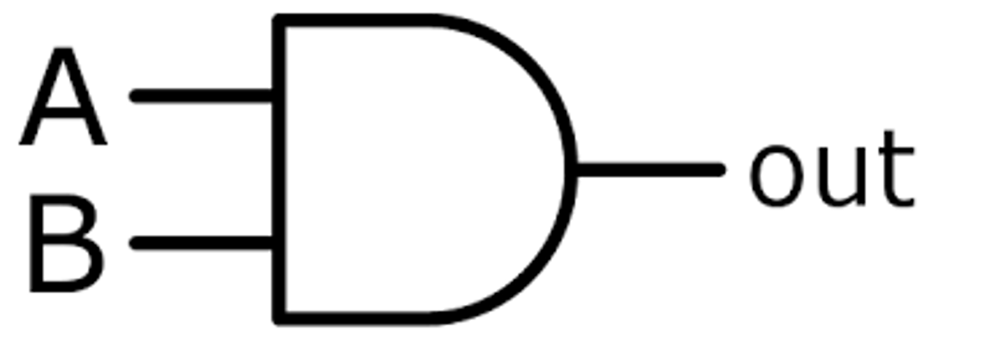
AND gate description
A logic gate that has two inputs. If both inputs are '1' it will output '1', otherwise it will output '0'.
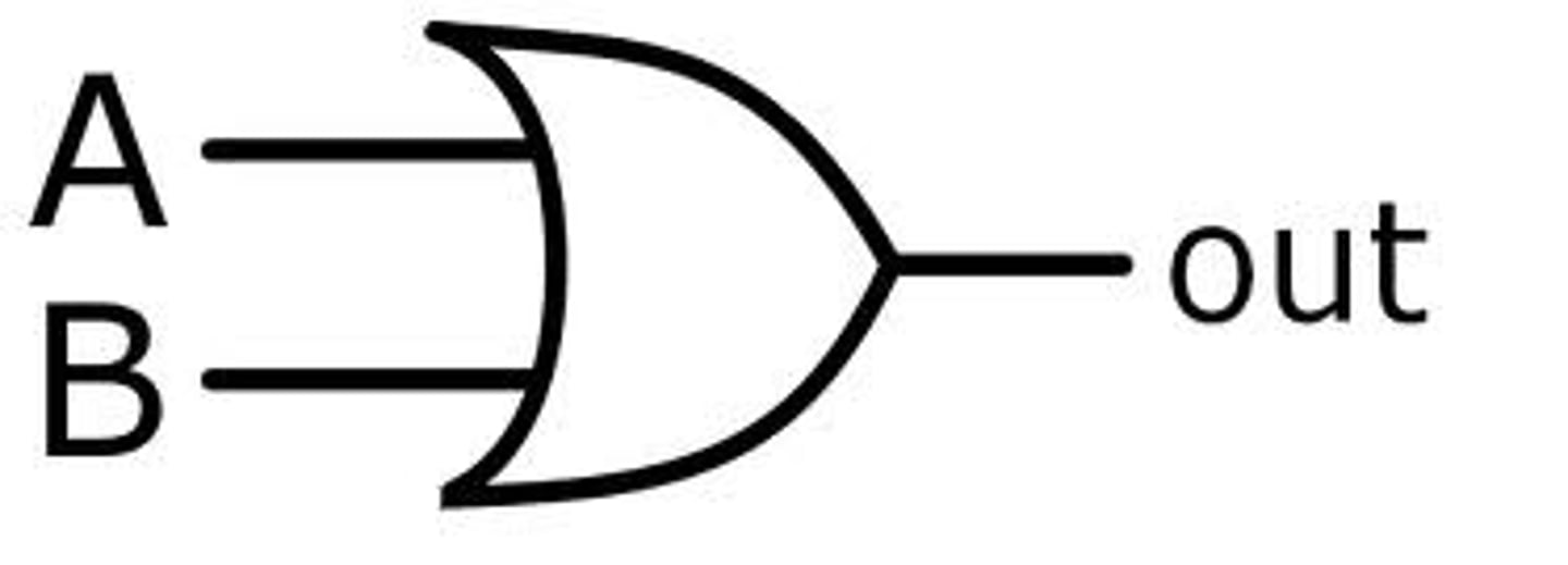
OR gate description
A logic gate that has two inputs. If either or both of the two inputs is '1', its output is '1'
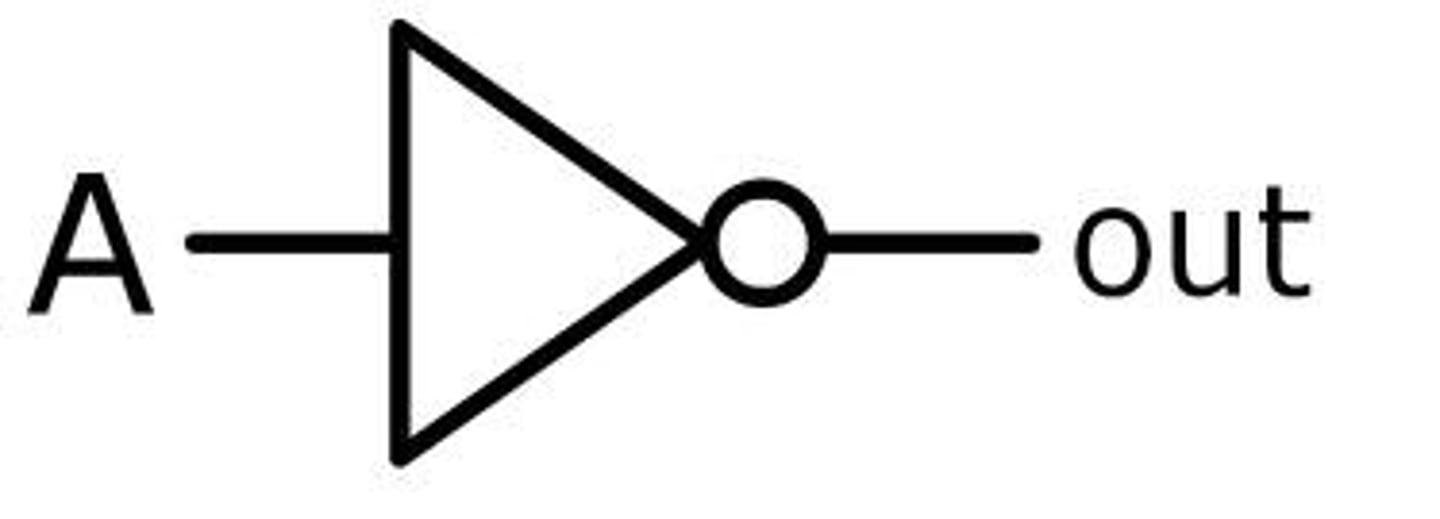
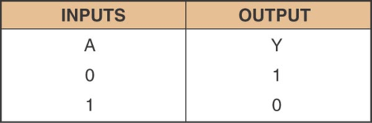
NOT gate description
A logic gate that has one input. If the input is '0', its output is '1'. If the input is '1', its output is '0'
Also called an INVERTER gate.
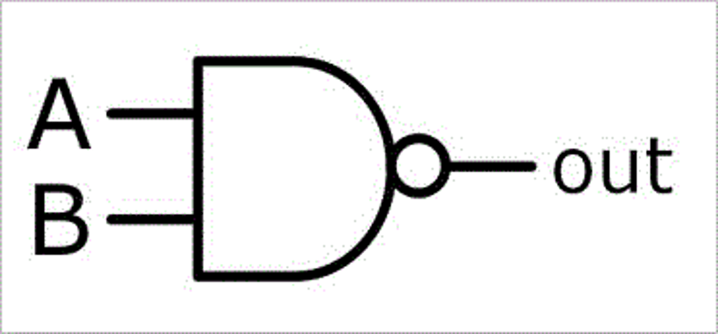
NAND gate description
Combination of a NOT and an AND gate. If an AND gate gives an output of 0, then this gate gives an output of 1
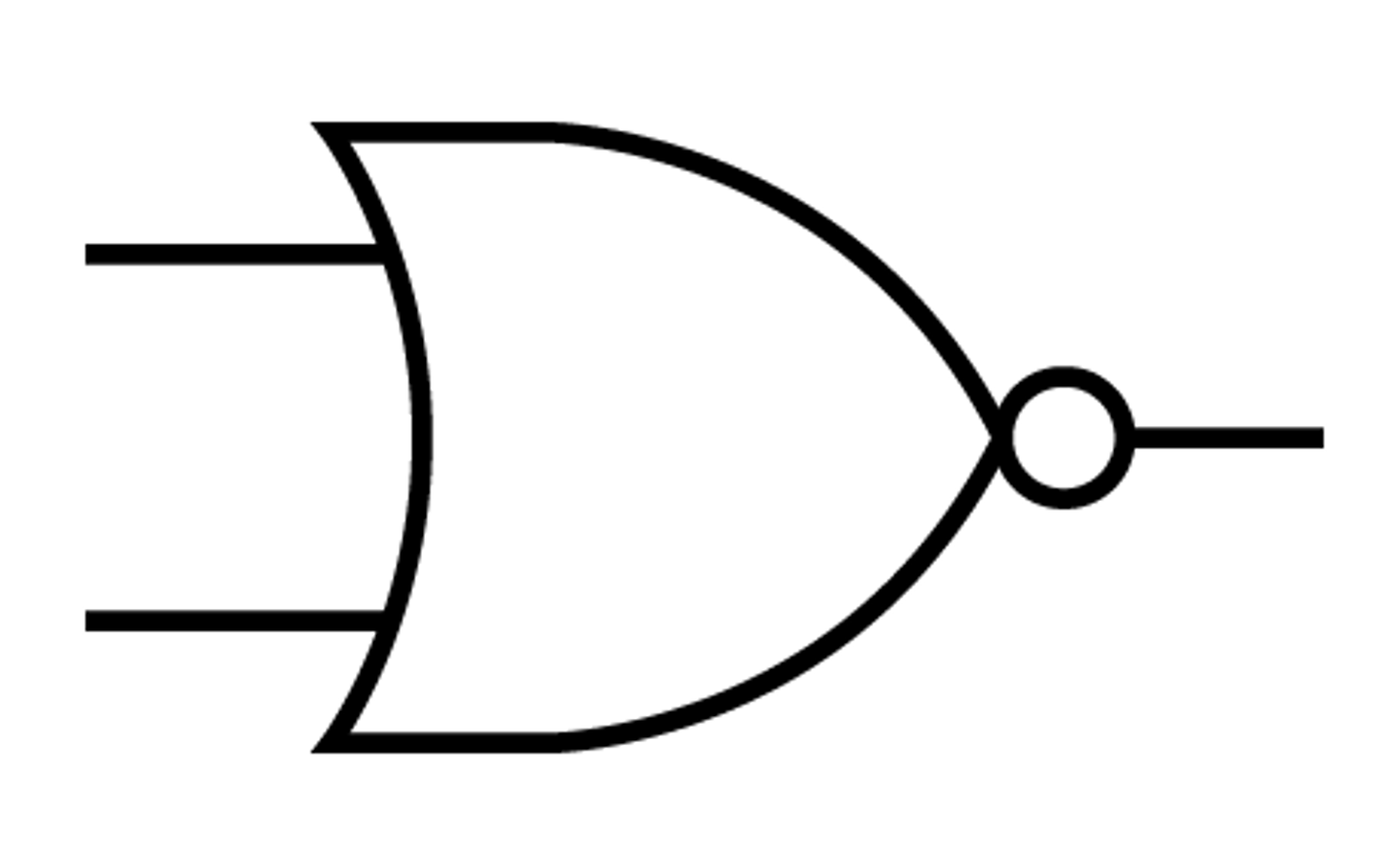
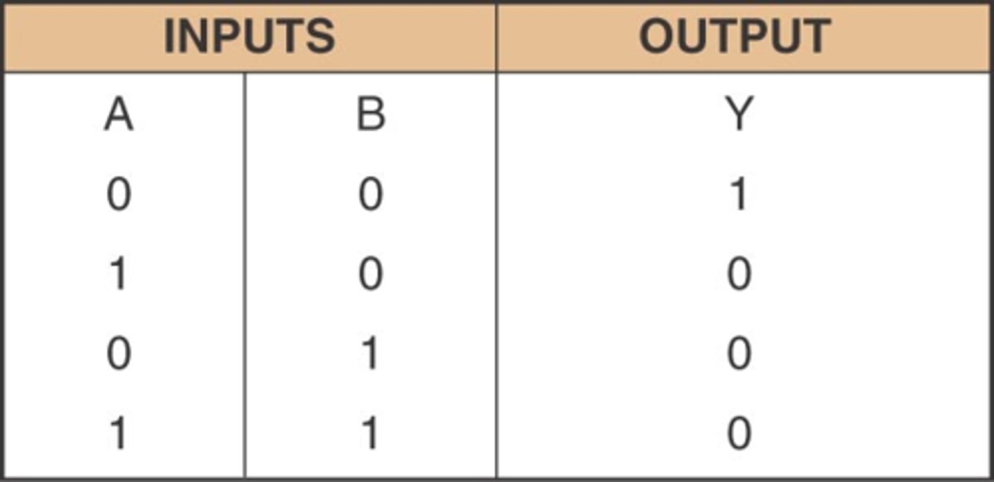
NOR gate description
Logic circuit that operates like an OR gate followed by an INVERTER. The output of this gate is LOW (logic level 0) when any or all inputs are HIGH (logic level 1).
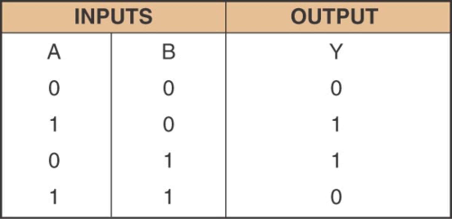
XOR gate description
A logic gate that outputs HIGH (logic level 1) when only one of its inputs is HIGH (logic level 1)
NAND gate symbol
AND gate symbol
NOT gate symbol
OR gate symbol
NOR gate symbol
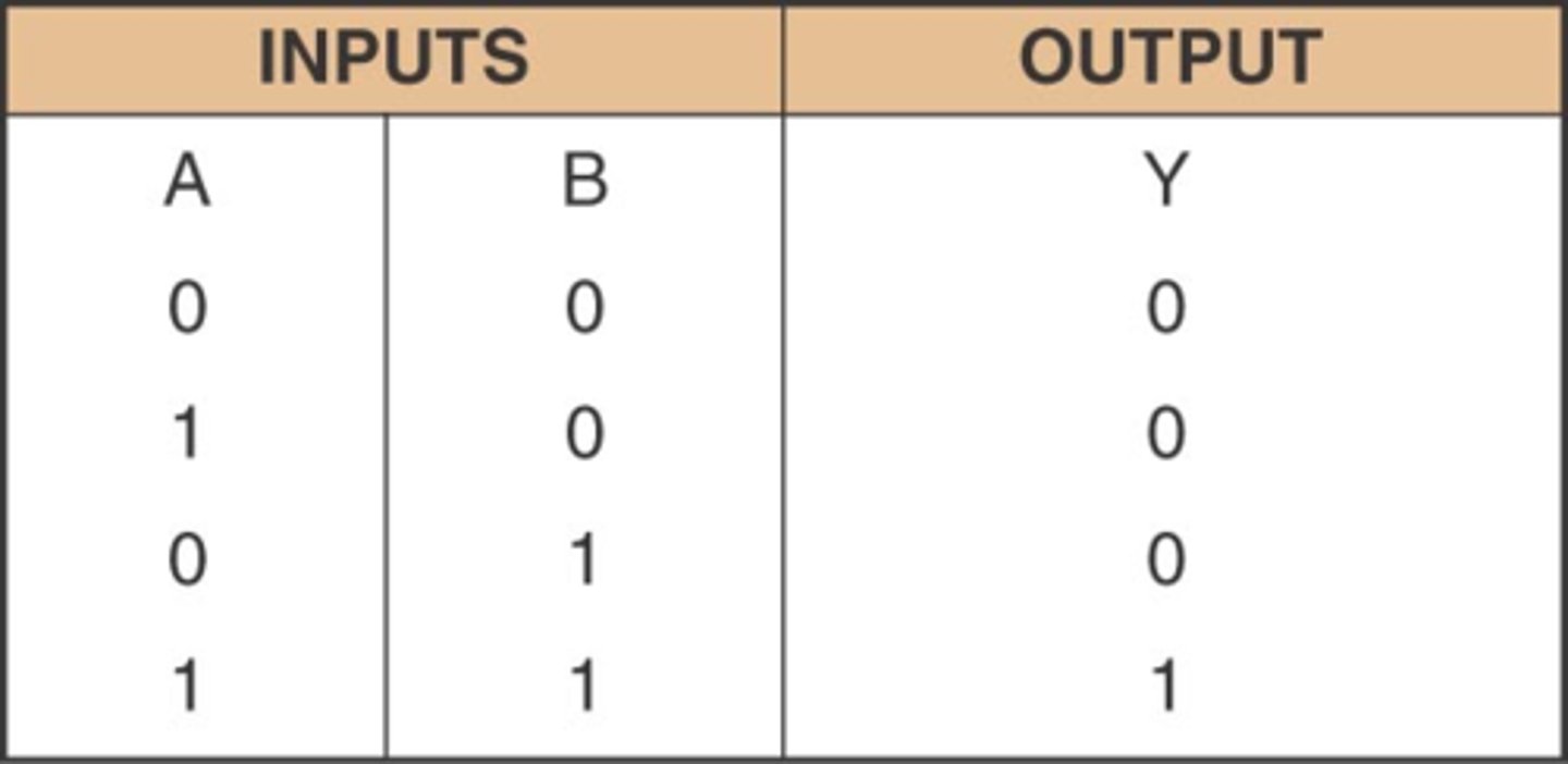
AND truth table
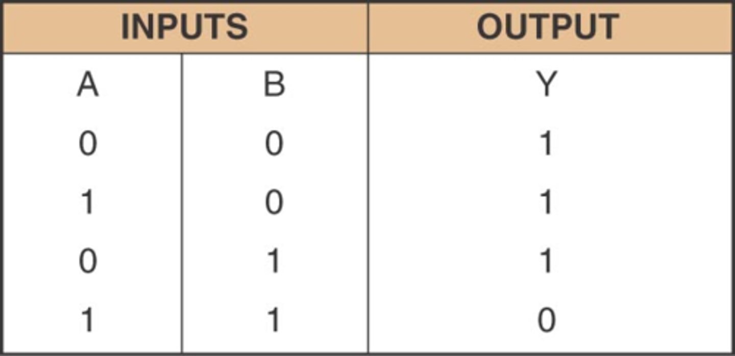
NAND truth table
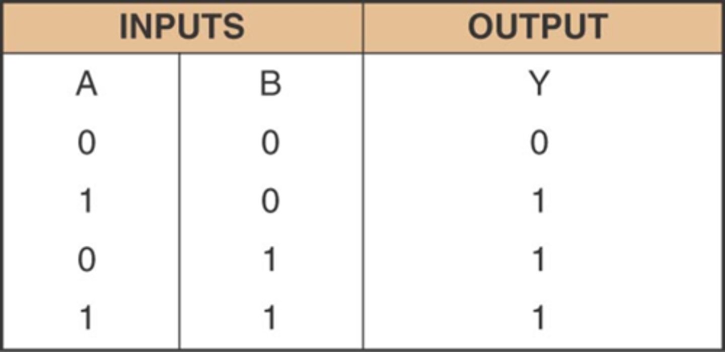
OR truth table
NOT truth table
NOR truth table
XOR truth table
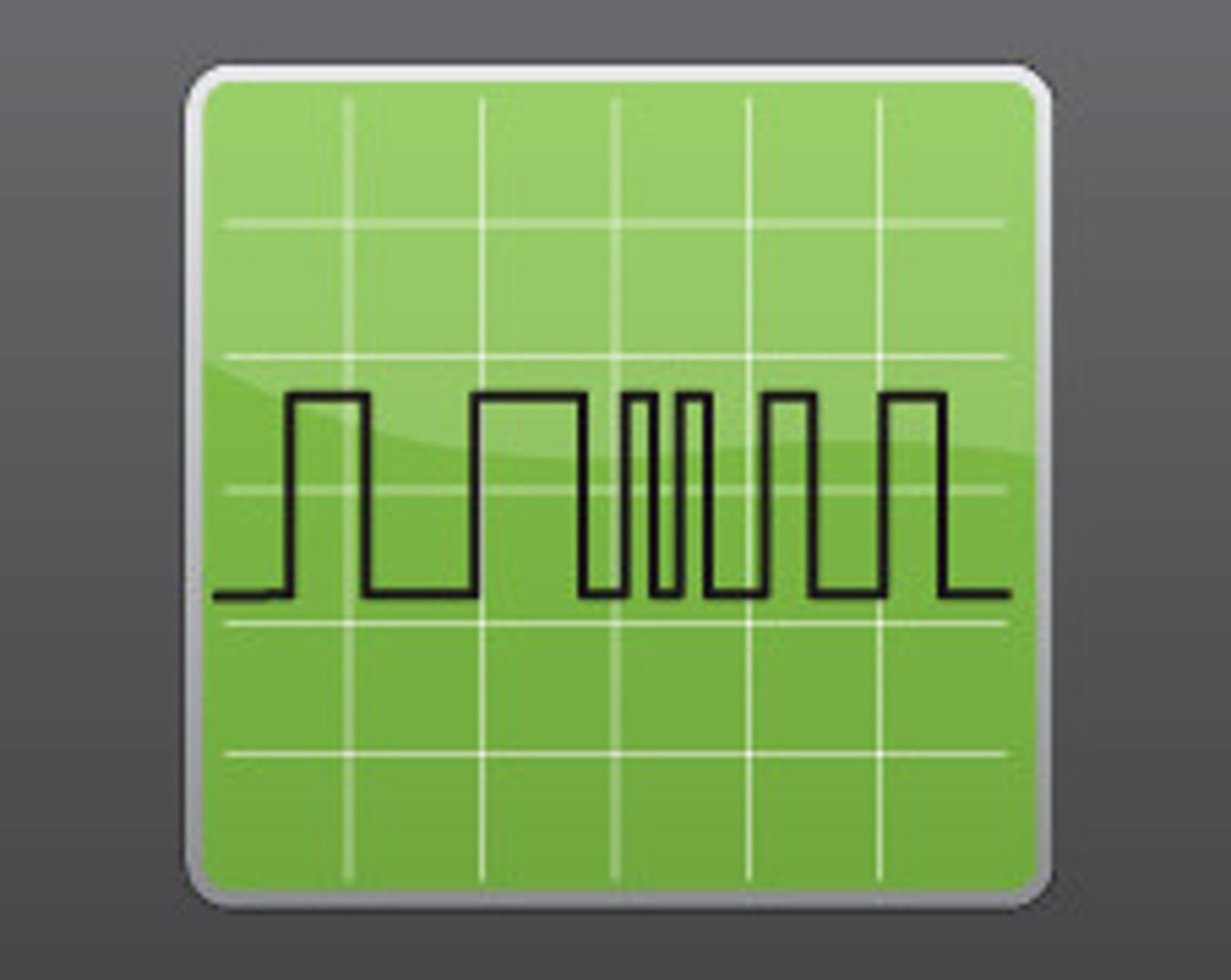
Digital signal description
A system of discrete states: high or low, on or off, 1 or O.
Analogue signal

Digital signal
Analogue signal
A system where the data varies continuously with time and can have any value between two limits.
XOR gate symbol