Mech Behahvior Final
1/76
There's no tags or description
Looks like no tags are added yet.
Name | Mastery | Learn | Test | Matching | Spaced | Call with Kai |
|---|
No analytics yet
Send a link to your students to track their progress
77 Terms
What are stress concentration factors
Factors applied to the total stress that increase the value locally due to geometric features
What factors influence the stress concentration at a crack and how do these factors affect the value
a:the major axis
b: minor axis
rho: radius of curvature at crack tip
kt is greatest when a/b is very large and rho is small
According to Griffith when does a crack increase in size
When the released elastic energy at the singularity exceeds the material’s resistance to cracking which is the energy of creating two new surfaces or 2*gamma
What factors affect fracture stress in the Griffith model and do they increase or decrease fracture stress
increase: E, surface energy
Decrease: crack size
What is the main limitation of the Griffith model and how does the Irwin model improve on it
Griffith did not consider the plastic deformation at the crack tip which plays a considerable role in fracture stress especially in ductile materials. This approach underestimates fracture stress.
What are the biggest issues with these models (Irwin and Griffith)
The plate is assumed to be infinitely large, surface energy and work of plasticity at crack tip are hard to measure
What is the stress intensity factor K and the critical stress intensity factor KIC
It defines the concentration of stress at a crack tip and the onset of rapid crack propagation and fracture
Why is type I fracture used as the default
Type one is opening which is common in tensile loading and is the most applicable to engineering applications as it will often occur before the other failure modes occur. Type 2 is sliding which is caused by shear stress in the same plane as the crack. Type III is occurs during torsion, crack surfaces move out of plane relative to each other
What are the assumptions used in defining K stress intensity factor
The cracked body is loaded in the linear elastic region and stress far from the crack tip is below the yield stress
All plastic deformation occurs at the crack tip which is a relatively small area in comparison to the rest of the body
Material is isotropic and strain is time independent
2D planar problem
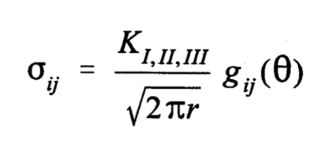
What are the critical findings about the stress distribution around a crack tip
The stress distribution around any crack in a structure is of similar form and
depends on r and Θ
The difference between one cracked component and another lies in the
magnitude of the stress field parameter K
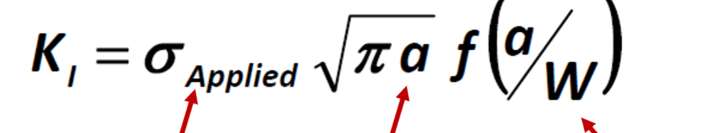
What factors affect K and do the increase or decrease its value
Increases: Applied stress, crack length, sharpness of the crack f(a/W)
Which of the following is not an assumption used for the development of the stress
intensity factor?
a. Small-scale yielding
b. Material is isotropic
c. Deformation is time-independent
d. Deformation far from the crack is nonlinear elastic.
d. Deformation far from the crack is nonlinear elastic.
As discussed in class, the primary assumptions for the development of the stress intensity factor
is that small-scale yielding (plasticity contained local to crack tip), deformation is time-
dependent, the material is isotropic, and the deformation far from the crack is linearly-elastic
(hence the use of linear elastic fracture mechanics).
T/F: Use of the compliance method developed by Irwin is limited due to an inability to
account for variations in component geometry.
a. True
b. False
b. False
As we discussed in class, the power of the compliance method that Irwin proposed is that it does
account for the influence of “body geometry” on the strain energy release rate. Therefore, the
answer to the above question is false.
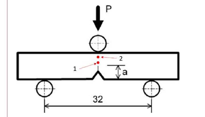
Consider a single-edge notch bending specimen loaded as shown in the attached image.
What is the relationship between the stress intensity at location 1 and location 2?
a. K1 = K2
b. K1 > K2
c. K1 < K2
a. K1 = K2
Recall that the power of K is that it is constant across the specimen for a given crack length,
applied stress, and geometry. This is why the stress intensity approach for fracture mechanics is
so much more powerful than a simple stress-based approach; the stress is shown to clearly vary
with angle and radius from the crack tip. As such, the answer is A
T/F: The localized stresses in front of a crack tip are calculated using the radius and
angle from the crack tip as well as the applied stress intensity. These are plastic stresses.
a. True
b. False
b. False
Remember that this approach is based on elasticity, therefore the stresses described by the
formula presented in slides are elastic stresses and not plastic stresses. Therefore, the answer is
false.
Fill in the blank: The fracture toughness of a material will _____ with increasing
thickness or yield strength due to an ______ in ______.
a. Decrease, increase, constraint.
b. Increase, decrease, constraint.
c. Decrease, increase, yielding.
d. Decrease, increase, plane strain fracture toughness.
a. Decrease, increase, constraint
Recall that increasing thickness or yield strength will modify the fraction of the specimen
experiencing a plane strain stress state (increases), resulting in additional constraint. As we
discussed repeatedly in class, this increase in constraint will increase the localized hydrostatic
stress, thereby causing a decrease in fracture toughness. Therefore, the correct response is A.
What are the three regions of the plastic zone around a crack tip
Farthest away, stress and strain are elastic, stress is equal to applied stress
closer, stress and strain are elastic, but stress is amplified by stress intensity factor
Directly at crack tip, significant plastic deformation as elastic stress approaches infinity
What are the assumptions used to calculate the plastic zone diameter
plane stress (sigma z = 0), tresca yield criteria
what factors affect the diameter of the plastic zone
Increase: stress intensity factor K
Decrease: Yield stress
Why is the plastic zone for plane stress bigger than for plane strain, and how do these stress conditions affect fracture
Plane strain has greater constraint as it cannot deform in the z direction. This constrain causes higher hydrostatic stresses which cause fracture, making plane strain conditions prone to brittle fracture and low fracture toughness
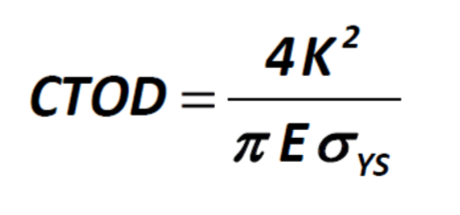
What factors affect the CTOD or crack tip opening displacement for blunted tip cracks
Increases: K
Decreases: E, yield strength
The size of the plastic zone changes depending on the through
thickness location. WHY? What is the significance?
Because the outside surface of the cracked body cannot experience a normal stress on that face making sigma z = 0 and causing plane stress conditions while the center of the body is under plane strain due to constraint from the elastic region in the z direction. Depending on the thickness of the sample the majority of the sample could either be in plane strain or plane stress which affects the fracture toughness and ductility of the sample.
What factors increase the constraint on a sample and how does this affect toughness?
Increasing yield strength and body thickness, and lowering stress intensity increases constraint and lowers toughness
Why does increasing yield strength and decreasing temperature lower toughness
These two factors decrease the work of plasticity and therefore the critical driving for fracture
What four factors are used in a Charpy test to cause fracture instead of yielding
Notch, low temperature, high strain rate, geometric constraint
What are the advantages and disadvantages of using Charpy and plane strain toughness tests
Charpy: very cheap and easy to perform, but not quantitative
Plane strain: quantitative, but expensive and difficult
What is microvoid fracture
This is ductile fracture where microvoids nucleate, grow, and coalesce due to increasing plastic strain, often beginning at the interface between second phase particles and the matrix
What are the three stages of microvoid fracture and what happens during each
Nucleation: cracks form from second phase particle cracking or particle decohesion from the interface
Growth: cracks grow under continued strain
Coalescence: microvoids join together due to flow localization and local necking
At what strains do microvoids begin to nucleate
at one tenth of fracture strain
How can precipitates be designed to prevent cracking and decohesion? And what should be avoided?
Keep them at relatively small size (20-200nm) and lower volume fraction
Avoid large particles (1-50 microns) and clusters or stringers of precipitates
Alloy toughness (increases/decreases) as growth stage is prolonged
Increases
What factors increase growth rate/decrease length growth stage?
Large inclusions, high yield strength, high mean stress
What are the two mechanisms for void coalescence
Internal Necking: area between voids thins and causes higher stresses in those areas
Void Sheeting: voids align at 45 degree angle with the loading direction and coalesce along this shear plane
At what point in a tensile test do most voids nucleate
During the onset of necking when triaxiality develops
Why does cup and cone fracture occur
Because there is greater constraint at the center of the sample, so hydrostatic stress is greater and failure occurs by coalescence. At the edges, there is less constrain and shear stress dominates which reaches its maximum at 45 degrees to the loading direction
How does increasing triaxiality affect microvoid behavior
Microvoid nucleation strain decreases
• Microvoid growth rate is increased
• Void coalescence promoted at lower strain, leading to lower failure strain
Why does increasing sulfur content in steel decrease toughness and how to fix?
Forms MnS particles that tend to align in stringers and do not dissolve during thermo-mechanical processing.
To fix:
• Reduce MnS size or modify shape
• Reduce volume fraction of MnS
• Increase MnS spacing
• Homogenize MnS distribution
This can be done by purifying the melt to remove S, N, H, and O, or by adding Ca and Ce which preferentially form particles with S that bond better to the matrix, are spherical instead of elongated, and have more similar deformation behavior to the matrix
Why are Fe and Si undesirable in Al alloys
Because they form large inclusions
Why does the plane strain fracture toughness of Al alloys depend on orientation? and is crack formation from TMP parallel or perpendicular to weakened planes
Particles become aligned during TMP forming stringers, crack formation in parallel to weakened planes
What factors promote cleavage and why
High strain rate, low temperature, stress state constraint because they all increase the yield strength, so fracture happens before yielding
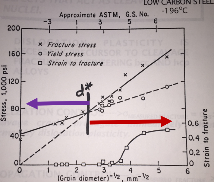
How does grain size affect fracture
Larger grains are more prone to brittle fracture and have lower fracture stress. In large grained materials fracture stress is less than yield strength, but does not fracture due to lack of crack nucleation, but at yielding dislocations allow for easy crack nucleation and fracture happens immediately as the conditions for fracture are already met. In small grained materials fracture stress is greater than yield stress so when crack nucleate during yielding they must first propagate until fracture causing ductile behavior
How do precipitates interact with dislocations to produce cleavage cracks and how can this effect be controlled
Upon yielding dislocations pile up at the grain boundary and apply pressure to grain boundary precipitates (carbides) until the precipitate cracks under the stress. The carbide size can be limited by decreasing the size of the grain boundary
How can steels be engineered to resist cleavage
Decrease plasticity induced effects by decreasing oxygen, carbon, and sulfur content
Add Nickel to increase intrinsic lattice resistance to cleavage and increase stacking fault energy to promote cross slip
Reduce grain size
Why are ceramics brittle
Complex crystal structures resist plasticity and slip
Why is ceramic fracture probabilistic
Because of a lack of plasticity, cracks tips do not get blunted and stress concentrations increase
What factors increase the probability of ceramic fracture and which decrease it
Increase: Volume, weibull modulus, applied tress
Decrease: sigma0 and V0
What is fatigue
Fracture based on the repeated cycling of stresses above or below the yield stress
What are the four stages of fatigue damage
Cyclic plastic deformation: plastic deformation occurs from cyclic loading
Microcrack nucleation: local stress concentrations cause microcracks to form
Small crack linkup and early growth: cracks grow and coalesce
Macrocrack propagation: large crack propagates and eventually causes failure
What is cyclic strain softening/hardening?
As plastic deformation accumulates over cyclic softening it forms a hysteresis loop that eventually becomes saturated and maintains a constant path as cycles continue. Cyclic strain hardening is when a material becomes stronger as cycles continue while softening is when it becomes weaker with more cycles
What determines whether a material will experience cyclic hardening or cyclic softening,how does SFE affect this
Soft metal will generally get harder as deformation density increases with plasticity forming LEDS structures
Hard metal will get softer as LEDS structures reform with more dislocations which are less resistant to dislocation propagation
High SFE materials tend towards one saturation state whether they began as hard and got softer or if they began as soft and got harder. This is because cross slip is easier and so organizing into an optimal LEDS structure is easier
Low SFE materials will tend towards two different saturation states depending on whether they started as hard or soft due to the difficulty of cross-slip
What is the difference between low cycle fatigue and high cycle fatigue
Low cycle fatigue has stresses that exceed the yield strength and fracture sooner, high cycle fatigue stays below the yield stress
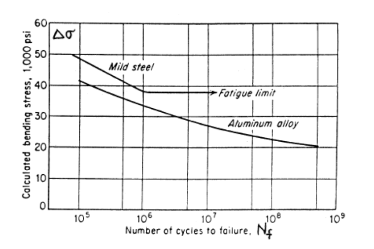
What is the endurance limit of a material and which materials have defined endurance limits
The endurance limit is the stress at which fatigue fracture does not occur, or occurs at a very large number of cycles. This behavior is more common in low strength materials and materials that exhibit work hardening
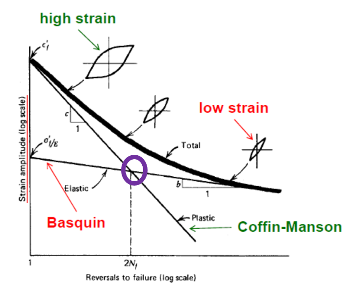
What is transition fatigue life
The amount of cycles it takes to transition from plastic strain dominated LCF to elastic strain dominated HCF
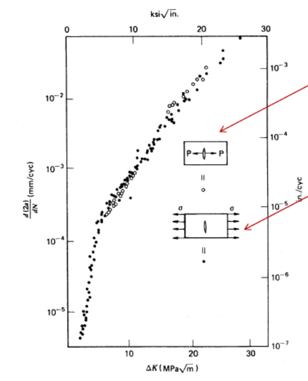
How does this image prove dependence of da/dN on ΔK and not Δsigma
A center cracked sample was loaded in two different ways that have the same Δsigma but different ΔK values, when the loading changed, the slope of the graph also changed
Why does Paris law not hold for high and low ΔK
At low ΔK may be below ΔKth which is the threshold below which crack growth is unlikely. At high ΔK Kmax approaches KIC and crack propagates at the speed of sound
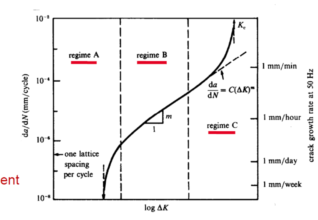
Explain the factors that impact each of the three regimes
Microstructure (precipitates, grain boundaries), Load ratio, environment (corrosion)
Paris regime, predictable growth, little influence of microstructure, R, thickness, environment
Large influence of Microstructure, R, thickness, minor influence of environment
How can da/dN be less than one lattice spacing per cycle?
The crack grows by a lattice spacing or more only every several cycles
T/F: Fatigue does not occur when the remotely applied stresses are elastic.
False
T/F: During cyclic plastic deformation, dislocation structure changes mechanistically govern why hard metals soften and soft metals harden.
True
Which of the following is not a common characteristic of a high cycle fatigue S-N curve?
Cyclic life increases as stress range decreases.
Increasing mean stress during testing leads to a longer fatigue life.
An endurance limit can exist where below which fatigue failure does not occur.
Notches and defects reduce fatigue life.
Increasing mean stress during testing leads to a longer fatigue life.
What does the transition fatigue life represent numerically?
The fatigue life produced by equal elastic and plastic strain ranges
The onset of the endurance limit
The transition from crack nucleation to crack propagation
The first datapoint measured on the S-N curve
The fatigue life produced by equal elastic and plastic strain ranges
T/F: Final fracture from fatigue is physically due to the applied maximum K exceeding the fracture toughness of the material.
True
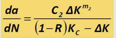
Why does compressive stress (R<0) cause minimal fatigue damage
Because crack surfaces touch and the crack closes which does not add to the deformation at the crack tip and instead transfers the stress normally to the rest of the material. This causes a decrease in the effective stress intensity lowering crack growth
What is the Forman equation useful for
For predicting crack growth behavior at high Kmax values as K approach KIC
How is the Paris equation modified when R<0
ΔKeff is used instead of ΔK where ΔKeff = Kmax - Kop
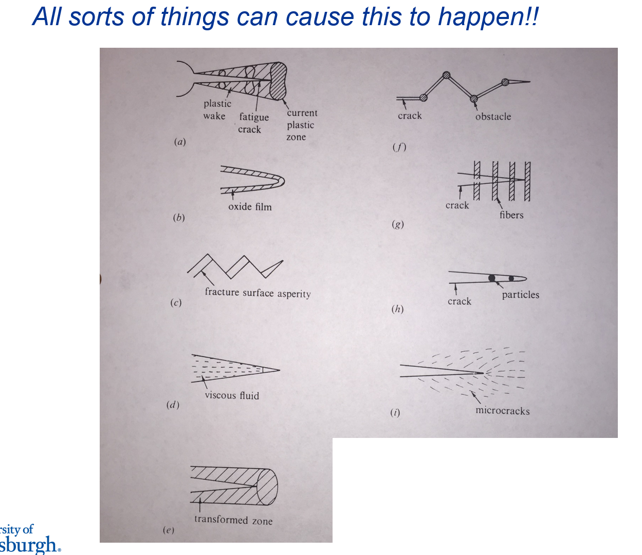
What factors can prevent crack opening
a. plasticity induced closure: Deformation leaves behind plastic region around the crack that bulges and keeps surfaces in contact
b. oxide induced closure: oxide film builds up in the crack surface and partially closes it
c. Surface roughness induced closure: fracture surface is jagged from interactions with the microstructure and varying slip planes. This roughness can cause the surfaces to interlock and require additional stress to open
d. Fluid induced closure: when fluid enters the crack it may cause pressure within the crack to keep it closed
e. Transformation induced closure: Strain at crack tip causes phase transformation and volume expansion closing the crack
i. Microcrack shielding: Microcracks around the crack absorb energy and redistribute stress
How does the plastic zone change when in tension and compression
It grows in tension and shrinks in compression
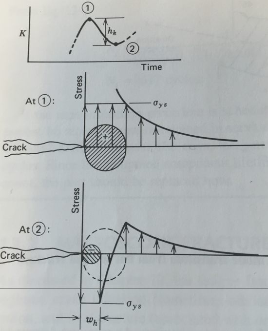
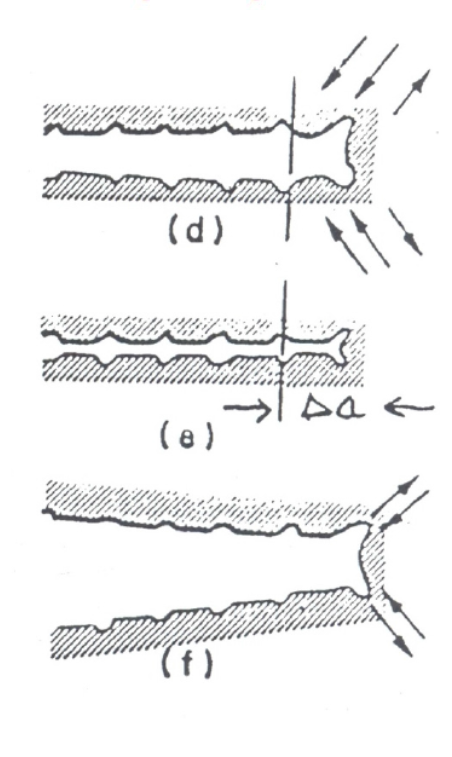
What causes striations in fatigue fracture surfaces
Laird and Smith blunting and buckling hypothesis: Tensile loading causes slip at 40 and 60 degree angles and blunts the crack tip at Kmax. During unloading crack tip folds and buckles to create notches (striations). These represent crack growth per cycle.
What are the four design practices used to predict fatigue failure
Static strength: Based solely on yield strength and satety factor
Safe life: Calculate cycles to failure using Basquin and Coffin-Manson and divide by four
Fail Safe: Design based on Paris law that ensures crack growth is slow enough to be detetcted before failure
Damage Tolerance: Builds off fail safe, ensure that subcritical cracking is found, periodically inspect and ensure that small defects will not cause failure before next inspection
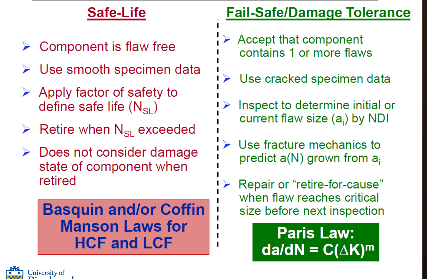
What are the limitations to safe life design
Retires functional components
Does not quantitatively account for flaws and geometry size effects
Inaccurate if test specimen has different flaw distribution than large component (Weibull)
What is the practical limitation to testing ΔK vs da/dN?
Environment and time can have a large impact on the graph. Testing occurs in a totally inert environment to baseline considering plastic deformation only. Any other environment will increase da/dN, decrease ΔKth, lead to multi-slope power law behavior, and cause time dependence
T/F: The cyclic plastic zone is larger than the monotonic plastic zone for the same applied
K and material.
False
Fill in the blanks: A _____ metal would have the best fatigue resistance in the Coffin-
Manson regime, while a ______ metal would have the best fatigue resistance in the
Basquin regime.
a. Ductile, strong.
b. Tough, strong.
c. Strong, tough.
d. Tough, ductile.
a. Ductile, strong.
As is shown in the notes, strong metals will perform well in the Basquin regime because the
loading is elastic. On the other hand, ductile materials should be expected to perform well in the
Coffin-Manson regime due to the dependence on plastic strain, which ductile materials can more
easily accommodate.
T/F: The safe life approach for managing fatigue in structural components typically leads
to a lower usable life than damage tolerance approaches because the component must
be retired upon reaching a predetermined lifetime in service.
True
T/F: Stress intensity similitude in the context of fatigue means that, for a single geometry,
two different materials (nickel and steel) will exhibit fatigue cracks that grow at equal
rates if subjected to the same ΔK.
False
When crack closure occurs, does the applied stress intensity range increase, decrease, or
stay the same?
a. Decrease
b. Increase
c. Stay the same.
Decrease