LMECA2220 - Theory Questions
1/60
There's no tags or description
Looks like no tags are added yet.
Name | Mastery | Learn | Test | Matching | Spaced | Call with Kai |
|---|
No analytics yet
Send a link to your students to track their progress
61 Terms
What is the Sabathé (limited pressure) cycle? How does it compare to the Beau de Rochas (Otto) and Diesel cycles, and what is its specific interest? - [slide 21 CM1]
The Sabathé cycle, combines the features of the Otto (constant volume heat add) and Diesel cycles (constant pressure heat addition).
Heat is added sequentially: first at a constant volume (like an Otto; premix burn), and then at a constant pressure (like a Diesel cycle).
Its specific interest is that it more accurately models the actual pressure-volume evolution of a real internal combustion engine.
While the Otto cycle is theoretically the most efficient for a fixed compression ratio, real engines are structurally limited by their maximum peak pressure. If peak pressure is the limiting constraint, the Sabathé or Diesel cycle actually offers the best efficiency.
What is the interest and functioning principle of an Argon engine? Why do we want to increase the gamma value, and why does this require a low compression ratio?
- An Argon engine replaces the nitrogen (γ = 1.4) found in standard air with argon gas (γ = 1.65).
- Increasing the specific heat ratio γ → less internal energy stored/absorbed per unit pressure rise → stronger pressure response to heat release → more of the combustion energy is converted into useful work ⇒ increases the efficiency.
- However, it requires a low compression ratio because the lower c_p heat capacity of argon causes temperatures to rise much faster during compression. A lower compression ratio is necessary to prevent the gas from reaching extreme temperatures that would cause premature auto-ignition (CI), or engine knock (SI).
Why do the compression ratio and the specific heat ratio (gamma) increase the thermodynamic efficiency? Provide a physical explanation. - [slide 13-14-15 CM1]
Higher compression ratio
higher pressure at the start of combustion -> higher peak combustion temperature T_max -> Carnot principle :a larger temperature gradient across the cycle = a higher theoretical conversion of heat to work
expansion stroke starts at this much higher pressure and a smaller volume -> hot gases have a much longer physical distance to push down on the piston
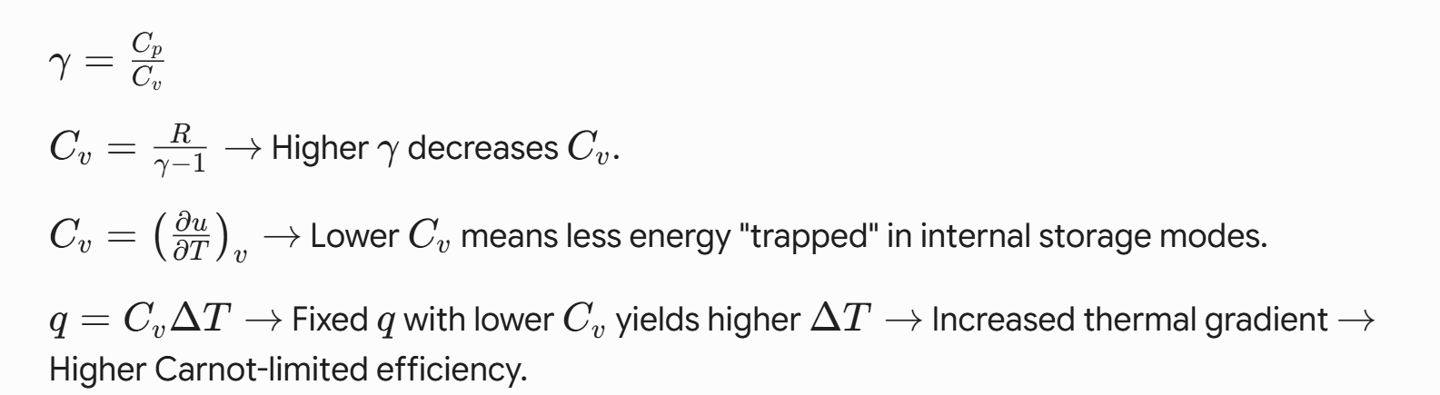
Higher specific heat ratio
Lower C_v means physically less energy is trapped as internal energy -> Higher ΔT during combustion leads to higher peak pressures, which allows the gas to do more work during expansion for the same amount of fuel energy.
How does the equivalence ratio (and thus the temperature) influence the thermodynamic efficiency of an engine?
The thermodynamic efficiency n_th = W / Q_in of an engine is governed by two primary factors: the intrinsic behavior and the extrinsic management of heat.
1. Intrinsic: Specific Heat Ratio γ
- Lower ϕ (leaner) results in a higher concentration of air
- and air has higher γ (compared to combustion products)
- Higher γ -> lower C_v -> higher ΔT for a given heat input -> higher expansion pressure -> higher conversion of heat to work.
2. Extrinsic: Heat Loss
- Heat transfer from the gas to the cylinder walls
- Lower ϕ (leaner) -> lower average combustion temperature -> smaller ΔT heat loss gradient = less leakage through walls (more fraction Q_in for work)
3. Peak Pressure
- Lower T also means lower pressure, weaker explasion force, and thus less work per cycle
Conclusion: Efficiency increases as ϕ decreases because the cycle benefits from a more favorable working fluid γ and lower external heat loss Q_loss
=> trade-off in engine design: running lean gives you great efficiency, but terrible peak power (IMEP)
How does the equivalence ratio mathematically and physically influence the Indicated Mean Effective Pressure (IMEP)? [CM4 slide 6 + extra]
What does the Indicated Mean Effective Pressure (IMEP) represent, is it a "true" physically measurable pressure, and what parameters influence it? [slide 29 CM2]
- A large engine automatically produces more work. So to compare two engines of different sizes we go from asking ourselves “how much work produced?” to “how effectivly does each unit of cilinder volume produce work?”
- not physically measurable = fictive constant pressure that would produce the same work as the actual cylinder cycle
- main parameters :
- equivalence ratio (ϕ) : directly fixes how much fuel mass can be burned given the available air (indirect effect on imep)
- volumetric efficiency (ϵ_v) : determines how much air mass enters the cylinder : More trapped air → more oxygen → more fuel can burn → higher total energy release → higher IMEP
- fuel's Lower Heating Value (LHV) : more chemical energy for same mass of fuel → higher imep
- combustion efficiency (η_c) : fraction of fuel energy actually released : higher η_c → more usable energy → higher imep
- internal thermodynamic efficiency (η_ti) : fraction of released heat converted into work : Higher η_ti = more heat becomes pressure work (less in heat losses) → higher IMEP
What are the origins, orders of magnitude, and influencing parameters of wall heat losses? - [page 7 CM3]
- Wall heat losses originate from the extreme temperature difference (ΔT) between the hot combustion gases and the cooler cylinder walls
- They typically consume between 10% and 20% of the total heat released by combustion
- heat loss is heavily influenced by engine geometry and operation:
- larger engine size (larger bore B) → less wall surface per unit of hot gas volume (most gas is far from wall) → fraction of gases affected by wall is smaller
- higher piston speed u → less time for heat transfers into wall
- increased volumetric efficiency e_v → more air intake, so more fuel can be injected (for same equivalence ratio) → more fuel, so more heat release (wall stays same) → wall losses represent smaller fraction of total energy
- decrease compression ratio → lower compression = lower peak T_max
What is the origin of radiation in a diesel engine? What would be the effect on the engine's efficiency if we assumed the walls were perfectly adiabatic? - [ ?? ]
- Origin: Diesel engines rely on a diffusion flame, which physically creates fuel-rich pockets that form heavy, carbon-rich soot particles. These soot particles glow intensely, making the flame highly emissive and causing up to 25% of the total wall heat loss to occur via radiation.
- Adiabatic Effect: (zero heat loss)
- More heat energy into usefull work : Engine’s (thermodynamic) efficiency would directly increase because the energy remains trapped to do expansion work.
- More combustion : Combustion efficiency would also increase. The trapped radiation would heat the boundary layers of gas right next to the walls, triggering auto-ignition in these normally "cold" zones and burning off fuel that would otherwise become unburned emissions
Is it physically possible to completely insulate a cylinder to eliminate wall heat losses, and what are the material challenges involved? [page 11 CM3]
- not physically possible to completely eliminate wall heat losses
- can significantly reduce them by adding insulation layers or building the cylinder walls out of low-thermal-conductivity ceramics
- material and mechanical challenges:
- The ideal material must have a very low thermal diffusivity (α) + low mass density (so that it doesn't simply absorb the heat itself) = very difficult to manufacture
- insulate the walls = they stay extremely hot → cause conventional engine oils/ lubricants to break down and fail
- insulate the walls = they stay extremely hot → heat the incoming fresh air → air expands = cannot pack as much oxygen into cylinder ⇒ kills volumetric efficiency
- insulate the walls = they stay extremely hot → can cause severe engine knock in SI engines
What is the physical meaning of the exhaust temperature (T5) compared to the end-of-expansion temperature (T4)? How do you calculate T5 from T4? - [slide 9 CM4 + extra]
- T_4 (End of Expansion) = This is the theoretical temperature of the gas trapped inside the cylinder at the exact end of the expansion stroke, right before the exhaust valve opens.
- T_5 (Exhaust Temperature) = This is the actual mixed temperature of the exhaust gases once they have escaped into the exhaust manifold (after blowdown / scanvenging T_5* + heat losses thourgh exhaust ~20%)
- end of expansion (T_4) → exhaust valve opens, high-pressure gas rushes out violently (= blowdown; free expansion work) T_b (<< T_4)→ piston moves up, gases pushed out (~isenthalpic; scavenging) T_s (< T_b) → mixed blowdown and scanvenged gases T_5* transfers heat to engine exhaust pipes → T_5 (<< T_4)
- Calculation :
- Adiabatic Exhaust Temperature (T_5) : from the overall energy balance of the exhaust event (H5-H1 = U4 - U1) (energy left in the exhaust stream = energy at the end of compression) → T_5*
- Actual exhaust temperature (T_5) : we account for the heat lost to the exhaust valve and port walls using a heat loss coefficient ϵ_LE ≈0.2)
What is a turbocharger, and what is its utility in an engine? - [slide 21 / page 6 CM4]
Turbocharger
A turbocharger consists of a compressor and a turbine coupled together on a single shaft.
Instead of letting the hot, high-pressure exhaust gases escape and waste their energy, the exhaust gases go through a turbine to spin it. This spins the compressor, which forces fresh air into the intake manifold.
Utility :
primary goal = increase the mass and density of air trapped in the cylinde (more air = more work)
packing more air in same volume (same engine size) = you can inject more fuel (for same ϕ) = increases the engine's power (IMEP)
What are the specific advantages of supercharging? Explain how Variable Turbine Geometry (VTG) and electric assistance improve this process. - [slide 21 / page 7 CM4]
Turbocharger and Supercharger both pack more air into cylinder via compressor. Turbocharger via exhaust gases in turbine that spins a compressor, Supercharger directly via crankshaft that spins a compressor.
physical advantage = no "turbo lag" (response time due to inertia of turbo for large turbos / at low rpm). Supercharger mechanically linked to the engine speed, so it provides an immediate boost (even at low rpm)
it’s important to mention that we design oversized turbochargers and use regulation (like VTG) to provide safe boost at lower rpm and bypasses exhaust gas around the turbine at higher rpm (with wastegate).
Variable Turbine Geometry (VTG) :
at low rpm (exhaust flow to weak), VTG adapts the incoming air flow (by narrowing the valve, exhaust flow accelerates and hits turbine blades with high velocity)
at high rpm (turbo can’t spin past it’s rpm limit / chocking risk) : the vane opens
engine computer physically changes the angle of these vanes to optimize the velocity and angle of the exhaust gases hitting the turbine blades
Electric Assistance:
At low RPMs or light loads = not enough exhaust energy spin a large turbocharger, so we add an electric motor directly to the compressor shaft (no more turbo lag / instant boost)
Which system is better for cylinder filling: a turbocharger or a mechanically driven supercharger?
A turbocharger is better for thermodynamic efficiency because it reuses normally wasted exhaust gas energy to compress the intake air and increase cylinder filling
but turbolag (response time due to inertia of turbo for large turbos / at low rpm)
systems like Variable Turbine Geometry (VTG) or Electric Assistance solve turbolag (but cost)
A supercharger uses mechanical power directly from the engine's crankshaft to increase cylinder filling (
= steals a part of usefull work → penalizes engine's overall efficiency
more reactive and provides high torque instantly (no turbo lag, even at low rpm)
What are the main sources and types of mechanical friction in an engine? - [slide 6-7 + graph on 10 CM5 + extra]
mechanical friction sources :
up to 75% : (majority) comes from the piston assembly (the rings scraping the cylinder and the skirt slapping the walls)
journal bearings (crankshaft and camshaft)
valve train (open/close engine valves) : only limited fraction of mechanical friction
auiliarie frictions (oil pump, water pump; scanvenge pumps,…)
different friction regimes :
- Boundary lubrification :
- metal-to-metal contact occurs (oil film too thin)
- happens at BDC/TDC for piston rings, where the piston physically stops and reverses direction (no oil film draged)
- generally constant and independent of engine speed
- Mixed lubrification : partial oli film
- Hydrodynamic lubrification :
thick film of pressurized oil completely separates the moving metal parts
occurs in the journal bearings and the piston skirt during the middle of the stroke
lineraly dependant on engin speed : the faster the engin speed = the more fluid shears
fmep (friction mean effective pressure) ~100…200 kPa
In terms of engine parts :
fmep_s : Piston ring friction (boundary friction, +-contant) ~50…100 kPa
fmep_p : Piston skirt friction (hydrodynamic friction, speed + B dependant) ~ 10…30 kPa
fmep_n : Journal bearing friction (speed + aspect design S/B dependant) ~ 10…30 kPa
in terms of physical contributions :
fmep_0 : constant elastic ring pre-tension, valve-train, …
load dependant term = proportional to gas pressure
speed dependant term = mean piston speed ( u/B)
Why do the Friction Mean Effective Pressure (FMEP) curves have a slight squared component as a function of engine speed, rather than being purely linear? - [slide 25 CM5]
Pure mechanical friction (rings, bearings) relies heavily on hydrodynamic oil shear, which increases mostly linearly with engine speed u
in some experimental settings (as it is difficult to isolate every individual loss) : FMEP_tot = FMEP + PMEP + AMEP (accessories).
the work required to pump gas into and out of the cylinder ("pumping of gas above the piston") is fundamentally excluded from pure mechanical FMEP (??)
PMEP = work required to pump air into and out of the engine → forcing gases past narrow valves = pressure drop (∝v² fluid velocity) → piston speed u∝ v ⇒ pressure drop ∝u² (Pumping work increases quadratically with rpm)
mechanically driven accessories like the water pump require torque that scales quadratically with rpm
windage = aerodynamic drag inside the crankcase (crankshaft generates turbulent flow that resists motion) → ∝v² fluid velocity ⇒ ∝u² piston speed
Why is it preferable to operate an engine at high load rather than part load, and how do downsizing and supercharging help achieve this? - [slide 30 CM5]
Downsizing = replace a large engine with a smaller one to drastically reduce mechanical friction and pumping losses
rappel - fmep physical contributions :
fmep_0 : constant elastic ring pre-tension, valve-train, …
load dependant term = proportional to gas pressure
speed dependant term = mean piston speed ( u/B)
running smaller engine at higher relative load (α = current power / max power) = reduces relativly the punitive effect of fmep_0
BUT !! maller displacement naturally = less power, so supercharging (or turbocharging) becomes indispensable → more air = allows to burn more fuel = higher IMEP
also reduces puming losses : the turbocharged engine operates closer to ambient intake pressure → for SI running at a higher load = throttle valve is kept wider open = eliminates wasteful pumping losses
combination maintains the vehicle's high power output while significantly cutting fuel consumption and CO2 emissions
What are the origins of the mechanical loads in a single-cylinder engine? - [slide 5 + extra CM6]
Gas Pressure (The Engine Cycle) :
during combustion, expanding gases exert a massive force pushing down on the piston and simultaneously pushing up on the cylinder head (naturally cancel each other out = internally balanced)
force is transmitted to bearing → crankshaft
pressure = generates the useful torque on the crankshaft
Inertia (Acceleration of Parts):
piston and connecting rod violently change direction and speed at the top and bottom of every stroke = inertia
inertial loads = vertical (oscillating) + rotational components
inertial loads ∝ rpm
not internally balanced → forces are transmitted directly to the engine mounts ⇒ cause the engine to vibrate
these sources change throughout engine cycle (time dependant) and introduce pitch / roll / yaw on engine block and crankshaft
How can you avoid or balance these mechanical loads in a multi-cylinder engine? - [slide 38 CM6]
- we take advantage of “multi-cylinder” to balance mechanical loads primarily through the physical architecture of the engine and the phasing of the cylinders.
- Balancing up-and-down (oscillating) forces of the piston :
- H1 (first order vibrations) : can be easily canceled out by phase-shifting the cylinders. ex : using an even number of cylinders phased by π
- H2 (second order vibrations) :
- Certain engines, like in-line 6- and 8-cylinder engines, are inherently balanced and naturally neutralize both H1 and H2!
- if engine architecture cannot naturally balance H2 → Lanchester method (= adding external balancing shafts that rotate at twice the engine speed (2ω) to physically cancel out the remaining vibrations)
- Balance centrifugal forces created by the rotational loads
- Integrated counterweights on the crankshaft physically cancel out the centrifugal (rotational) inertia forces created by the rotating mass of the connecting rod head, preventing them from transmitting to the main bearings
Why is the Lanchester balancer used to compensate for second-order forces and not first-order forces? - [extra slide 26 + 38 CM6]
- first-order (H1) forces can already naturally canceled out by the engine's physical geometry (easily canceled out by phase-shifting the cylinders)
- second-order (H2) forces cycle twice per engine revolution ∝ cos(2θ ) → so a phase shift actually make them sync and add up
- so we add two external balancing shafts that spin at exactly twice the engine (rpm) speed to physically counteract it
- 2 shafts = “you cancel vibration cleanly without introducing new motion”
- F_H2 ∝ cos(2θ) and external rotating shaft generates a force F∼cos(ωt), so to balance F_H2 we need 2ω
How do you justify the firing order of cylinders in a multi-cylinder engine, and is a perfectly regular firing order always possible?
- We want to keep the power delivery as smooth as possible. BUT torque fluctuates due to the combustion “cycles” and heavy inertial forces ⇒ we evenly distribute the firing events across the entire engine cycle
- firing order = designed to smooth out the engine's torque delivery + neutralize first-order mechanical vibrations
- a perfectly regular firing order :
- theroretically yes: if the crankpins are properly positioned and phased on the crankshaft ! (perfectly even firing intervals = 720°/n-cylinders)
- in reality : firing order must satisfy several incompatible constraints at once ⇒ trad-offs (compromise between smooth torque delivery, mechanical balance, and gas-dynamic efficiency, constrained by the fixed crank architecture)
What aerodynamic and geometric parameters dictate the dimensions of the intake and exhaust valves? - [slide 19 CM7]
at high rpm, if the flow accelerates past the speed of sound c, it chockes = cilinder cannot be filled, backward flow, vibrations,…
dimensionless number Mach index (Z ) is the ratio = (engine’s piston speed) / (speed of sound of air though valve)
To maintain good volumetric efficiency, we aim to keep the Mach index below Z < 0.6
Aerodynamic Parameters (c and T)
The local speed of sound c in a gas is dependant on its temperature
the speed of sound in cold intake air << speed on sound in hot exhaust gases (= cold intake air is much closer to chocking) ⇒ intake flow area must be larger than the exhaust flow area
the exhaust-to-intake area ratio is typically 70% to 80%
Geometric Parameters (u and B)
Because the piston speed u increases with rpm, to keep Z < 0.6 → need to increase valve “average opening area A” at higher rpm
this is why high performance engine cylinders use 4+ valves!
we also angle valves in a "pent-roof" shape to maximize the available surface area
Because the volume of gas that must be moved in and out of the engine ∝ B², the required valve area must also scale up proportionally ↔ the physical space available to fit these valves is strictly limited by the exact same bore diameter
When is it useful to open and close the different valves during the cycle, and what are the advantages and disadvantages of valve timing advances and delays? - [slide 31 + extra CM7]
Valve timing is highly dependent on engine speed (RPM) and load. We advance or delay valve openings and closings to balance volumetric efficiency, expansion work, and internal exhaust gas recirculation (EGR).
Intake
Opening
Early : air has longer time window to mix homogeneously
Late : at high rpm = more work to cleat out cylinder ; at low rpm = reduces internal EGR (stable combustion)
Closing = Has the largest impact on volumetric efficiency
Early : for low rpm = traps air perfectly ; at partial loads = replaces needs for throttle valve to regulate engine power (cuts pumping losses)
Late : at high rpm = packs extra air into cylinder ; at low rpm = fresh mixture flows backwards out
Exhaust
Opening
Early : at low rpm = waist high pressure energy (expansion work) ; at high rpm = MUST open early or huge back-pressure en puming losses
Late : at low rpm = extract maximum to expansion stroke ; at high rpm = puming losses
Closing
Early : at low rpm = imporved heating and evaporation of fresh mixture (high EGR) ; at high rpm = requieres more puming work to push exhaust out
Late : at high rpm = improved suction of fresh intake air (vacuum effet) ; at low rpm = sucks exhaust gas back into cylinder (EGR)
modern engines physically adapt these timings on the fly (Variable Valve Timing (VVT) )
What is the interest and principle of Variable Valve Timing (VVT) or a 3D variable camshaft? - [slide 33 CM7]
- Variable Valve Timing (VVT) = engine computer adjusts the exact moments when the intake and exhaust valves open and close during the engine cycle, reacting instantly to the current engine speed and load
- 3D variable camshaft = application of VVT, system physically twists camshaft from advance to late relative to engine’s rpm
- Interest : optimize engine’s "breathing" across all operating conditions to maximize thermodynamic efficiency, torque, and power
- At low rpm (camshaft set to early) : closes the intake valve early to prevent the fresh mixture from being pushed back out into the manifold
- At mid rpm : minimizes valve overlap to prevent exhaust backflow and ensure stable combustion
- At high rpm (camshaft set to late): It closes the intake valve late to take advantage of the incoming air's high inertia, packing more air into the cylinder to maximize volumetric efficiency
What parameters directly influence the volumetric efficiency (cylinder filling) in a 4-stroke engine? - [slide 35 CM7]
- Operating Temperatures (an thus rpm & load) : at low rpm, slow moving air absorbes heat → air expands = takes more space → less air can be packed in cylinder = kills volumetric efficiency r
- Engine Speed (RPM) & Load: At high rpm at moves fast → chocked flow at valve = air flow restricted + pressure losses. At low rpm : backflow of intake air back out in manifold
- Engine geometry: intake/exhaust manifold shape, valve area, and piston/head design determine flow resistance and pressure-wave behavior, which directly control how easily fresh air can fill the cylinder.
- Fuel & injection system: indirect injection or fuel vaporization in the intake displaces part of the air volume, reducing trapped air mass; direct injection leaves more room for air and improves volumetric efficiency.
- (Higher compression ratio → residual gases are hotter and expand more → occupy more volume during gas exchange → displace part of the fresh incoming air → volumetric efficiency decreases)
How does the scavenging/filling process work in a 2-stroke engine, and what are the specific problems linked to it?- [slide 45 + extra CM7]
- In a 2-stroke engine, the intake and exhaust phases occur simultaneously while the piston (acts as sliding door) is near BDC
- Process:
- Exhaust port opens → burnt gases start leaving due to cylinder pressure (blowdown)
- Intake ports open → pressurized fresh charge enters the cylinder
- Fresh charge flows through the cylinder, pushing/"scavenges" residual exhaust gas toward the exhaust port (designed to ptimally guide this air through the cylinder)
- Simultaneous flow: fresh charge + exhaust mix partially in the cylinder
- Exhaust port remains open → mixed gases exit while fresh charge continues entering
- Exhaust closes → remaining fresh charge is trapped
- Intake closes → compression starts with the remaining charge
- Problems:
- Waste : incoming mixture flows directly out the open exhaust port → wastes roughly 20% of the unburned fuel + creates massive hydrocarbon pollution
- Mixing : fresh charge inevitably mixes with the exiting exhaust gases (imperfect combustion)
- performance : to prevent an huge amount of fuel from escaping during scavenging, we must limit the cylinder filling (bmep onlt 75% of a comparable 4-stroke engine)
Why is there a critical auto-ignition temperature for fuels, does pressure influence it, and what are its physical limits? - [slide 24-25 + extra + 15 CM8]
- The combustion chain reaction is as follows :
- Initiation : heat cracks fuel molecules appart creating instable fragments
- Propagation : a radical steels an atom from a stable molecule creating → a new stable product +leaving behind a new radical
- Ramification : 1 radical creates multiplenew radicals (reaction explosion)
- Termination : Radicals collide with each other / with cilinder wall = form stable products
For the reaction to cause auto-ignition, the rate of creation (ramification) must exceed the rate of destruction (termination)
As the piston compresses and heats the mixture, the rates k change non-linearly until threshold and triggers the explosion
At this exact critical temperature, the reactions that create new radicals and the reactions that consume them are perfectly balanced
temperature provides kinetic energy to break bonds and pass activation barrier E_a more easily
Pressure does influence this critical temperature, but only slightly and mostly at very low values (no impact after 10 bars = easily reached during an engine's compression stroke). More pressure = packs molecules together and increases collison frequency A
physical limits of this critical temperature
Heavy fuels (diesel) : long carbon chains easliy break and form reactive radicals = easily auto-ignite (~ 250°C)
Light fuels (gasoline) : highly stable short molecular chains = resist auto-ignition (~ 400°C - 500°C)
What are the different types of radical reactions during combustion (initiation, propagation, branching, termination), and what is the interest of studying them separately? - [slide 24 + extra CM8]
- The combustion chain reaction is as follows :
- Initiation : heat cracks fuel molecules appart creating instable fragments (highly reactive radicals)
- Propagation : a radical steels an atom from a stable molecule creating → a new stable product +leaving behind a new radical
- Ramification : 1 radical creates multiplenew radicals (reaction explosion)
- Termination : Radicals collide with each other / with cilinder wall = form stable products
- each specific reaction responds differently to temperature and pressure changes using the Arrhenius equation
- must isolate these competing reaction rates (k_i) to mathematically determine a fuel's exact critical auto-ignition temperature
- For the reaction to cause auto-ignition, the rate of creation (ramification) must exceed the rate of destruction (termination)
Explain the Octane and Cetane numbers, the link between them, and what chemical structures make a "good" fuel for each? - [slide 18 - CM7 + slide 45 CM9 (SI) + ]
Octane Number (SI Engines) = Measures a fuel's resistance to auto-ignition (to prevent engine knock)
from 0 (n-heptane) → 100 (iso-octane) (standard min ~50)
Good Chemical Structures: Short carbon chains, branched (ramified) chains, unsaturated compounds (double bonds), and cyclic/aromatic compounds
Cetane Number (CI Diesel Engines) = fuel’s readiness to auto-ignite (= minimizes the ignition delay)
from 0 (alpha-methylnaphthalene) → 100 (n-cetane/hexadecane)
Good Chemical Structures: Long, straight, saturated, and non-cyclic carbon chains
Link Octane/Cetane Number : Because spark-ignition engines want to prevent auto-ignition while compression-ignition engines rely on it, a high Octane number inherently dictates a low Cetane number, and vice versa (!not the same scale!)
Explain the overall combustion process and flame propagation in an SI engine. - [slide 12 CM9]
Spark Ignition process :
takes place in a +- homogeneous mixture air-fuel (≠ diesel : combustion happens AS fuel is injected)
relies on a propagating flame front that travels across the entire combustion chamber
Main phases :
Initiation (Flame Genesis) ~ 5-10% of mixture burns :
A spark (electrical discharge across the spark plug electrodes) transfers electrical energy to the fuel-air mixture
a tiny, spherical volume of hot burned gas, surrounded by unburned gases, is created = flame kernel (very vulnerable!)
the kernel survives if it reaches a critical diameter and a sufficiently high temperature (the heat flux released by combustion must = heat demanded by surrounding unburned gas to initiate flame propagation process ↔ or else the cold unburned gas absorbes heat faster than the flame can generate it, and kerne dies)
Flame Propagation ~ 5-90% of mixture burns
- the established flame kerne propagates outwards into unburned mixture (as a thin, wrinkled sheet)
- at standard conditions the laminar flame speed is too slow ~0.4 m/s → accelerated by air intake turbulance (eddies distort flame front = increase total surface area = consume the unburned gas faster + higher apparent fmale speed BUT increase heat losses to wall!)
- the burned gases (between cylinder head and flame front) heat up and expand → act as a solid piston and compress remaining unburned gases ahead → temperature/pressure of those gases rise ⇒ burn faster (faster flame speed) BUT also increased knock tendency (auto-ignition arrives earlier)
- 3. Termination and Quenching ~90-9X% of mixture burns
- propagating flame front reach cool metal walls → violent heat loss → cooling slows down combustion reaction → flame dies (“quenches”)
- flame “quenches” before it can burn the final fuel molecules ⇒ unburned fuel (pollutants)
What parameters influence the laminar flame speed, and what is its typical value compared to actual turbulent flame speeds? - [slide 22 CM9]
- at standard conditions the laminar flame speed is ~0.4 m/s (slow)
- → accelerated by air intake turbulance (eddies distort flame front = increase total surface area = consume the unburned gas faster + higher apparent flame speed BUT increase heat losses to wall!)
- the actual turbulent flame speed= 3…30x laminar flame speed
- turbulance drives the apparant flame speed physically, but thermodynamically these parameters influence LAMINAR flame speed:
- Temperature of unburned gas : hotter unburned gas = burns faster (faster flame speed)
- Cylinder pressure : higher pressure = slightly reduces laminar speed
- Equivalence ratio : controls flame speed because it changes how strong and how hot the flame is (⇒ radical production+ adiabatic flame temp + reaction rate k)
- Residual gases : trapped exhaust gases or deliberate Exhaust Gas Recirculation (EGR) = dilute mixture → lower oxygen concentration → less radical production → less efficient heat release → slower reaction rates + reduced flame speed
Why do we usually operate SI engines at a stoichiometric equivalence ratio (ϕ = 1)? - [slide 23 CM9 + CM11]
Equivalence ratio : controls flame speed because it changes how strong and how hot the flame is (⇒ radical production+ adiabatic flame temp + reaction rate k)
Rich mixtures (ϕ>>1): too much fuel, insufficient oxygen → less radical production → less efficient heat release → slower reaction rates + reduced flame speed
Lean mixtures (ϕ << 1): too much air, insufficient fuel → lower fuel concentration and reduced radical pool → lower heat release rate and flame temperature → slower reaction rates + reduced flame speed
(SI) engines operate at a stoichiometric equivalence ratio (ϕ=1) primarily to meet strict environmental regulations :
At ϕ=1 ⇒ delicate chemical balance of a three-way catalyst is met → simultaneously neutralize the three major engine pollutants: carbon monoxide (CO), unburned hydrocarbons (HC), and nitrogen oxides (NOx)
Operating slightly lean (ϕ≈0.85) =
highest thermal efficiency + lowest fuel consumption
catalyst cannot effectively reduce toxic NOx in N2
Operating slightly rich (ϕ≈1.1) =
maximum engine power
not enough oxygen ⇒ surplus of unburned (unoxidized) CO and HC in the exhaust
What is engine knock, what causes it, and how can it be avoided through engine design and operating parameters? - [slide 42 CM9]
During flame propagation : the burned gases (between cylinder head and flame front) heat up and expand → act as a solid piston and compress remaining unburned gases ahead → temperature/pressure of those gases rise ⇒ burn faster (faster flame speed) BUT also increased knock tendency (auto-ignition arrives earlier)
knock = spontaneous auto-ignition of the unburned "end gas" ahead of the propagating flame front (creates violent, high-frequency pressure waves ⇒ damage the cylinder walls)
If this end gas stays above its critical auto-ignition temperature long enough before the flame reaches it, it explodes (so auto-ignition depends on temp AND on duration above that temp)
How to avoid knock :
Avoidance through Engine Design:
Chamber Geometry : small-diameter combustion chambers= small physical distance the flame must travel
Spark Placement: spark plug near the hot exhaust valves ⇒ unburned end gas is pushed into the cooler parts of the cylinder = preventing it from overheating
Turbulence: Maximizing in-cylinder turbulence (via geometries) = accelerates the flame speed
Compression Ratio: Lowering compression ratio = reduces peak cylinder temperatures and pressures = keeping the end gas cooler
Avoidance through Operating Parameters:
Spark Timing: Retarding the spark ignition timing shifts combustion slightly later into the expansion stroke, which naturally lowers the peak pressures and temperatures
EGR : exhaust gases reinjected act as a thermal sink → lowers the peak pressures and temperatures
Limiting turbocharger boost : lowers the peak pressures and temperatures
Fuel : high-octane fuels = better resistance to auto-ignition
Why are SI engines typically designed to be compact (small cylinder diameters)? - [slide 50 CM9]
- Small Chamber Geometry = prevents knock : small-diameter combustion chambers= small physical distance the flame must travel
- If this end gas stays above its critical auto-ignition temperature long enough before the flame reaches it, it explodes (so auto-ignition depends on temp AND on duration above that temp)
- Cylinder bore B >> → flame takes time to cross cylinder → delay gives the unburned "end gas" enough time to overheat → auto-ignition (damaging engine knock)
What are the main differences, advantages, and disadvantages of Port Fuel Injection (PFI) versus Direct Injection Spark Ignition (DISI)? - [slide 65- CM9]
In SI engines, the way fuel is introduced controls : mixture formation, combustion quality, and efficiency → different injection strategies exist
PFI (Port Fuel Injection):
= fuel is sprayed into the intake port (just before intake valve), and there it mixes with incoming fresh air
DISI (Direct Injection Spark Ignition):
= fuel is sprayed directly into the combustion chamber
Advantages
injecting liq fuel on metal cylinder → fuel vaporizes by absorbing heat = cooling effect ⇒ lower peak temperatures = improves knock resistance + (at high loads) intake air less heated, more dense, more air can be packed, so better volumetric efficiency
at low loads, SI engine with DI can operate “unthrottled” = cuts pumping losses (engine output is controlled by fuel (late) injection instead of a throttle valve = “stratified charge”, ignitable cloud concentrated at sparkplug)
heat losses : concentrating the combustion in the center of the chamber limits heat transfer losses to the cylinder walls
Disadvantages
Increased Pollution: fuel has less time to mix with the air → increased emissions (production of ultra-fine particulate matter (soot), + higher levels of unburned hydrocarbons and NOx)
What is the specific interest of using a stratified charge in an SI engine? - [slide 67-69 CM9]
- normally : throttle valve is used to restrict air intake and so controle engine output on SI engines
- with direct-injection, at low load, fuel is injected late and concentrated near the spark plug (= spatial separation of mixture strength) →
- Advantages :
- enables unthrottled operation and reducing pumping losses (even with lean mixtures, which also leads to highest thermal efficiency + lowest fuel consumption) - no wasted work to suck air in
- spatial separation between rich region near spark
and excess air → air acts as insulation from cylinder walls = reduces heat losses
What is the utility and functioning principle of a pre-chamber, particularly in stationary gas engines? - [slide 78 CM9]
- pre-chamber = seperate cavity above main cylinder, where a locally rich mixture is ignited first
- During the compression stroke, the piston pushes a portion of the unburned gas mixture into this pre-chamber
- in the small, concentrated volume, the spark easily initiates combustion
- high-pressure explosion inside the pre-chamber that shoots powerful "flame torches" out into the main cylinder
- allow the engine to run on very lean fuel-air mixtures (ϕ≈0.6) ⇒ highest thermal efficiency + lowest fuel consumption
Explain the chemical and physical evaporation process of a fuel droplet in a CI engine. - [slide 15 CM10]
- In a (direct injection) CI engine, fuel is blasted into compressed air at extreme pressures to shatter liquid fuel into microscopic droplets. But liquid fuel can’t burn, it must vaporize and mix with oxygen
- Physical Process (Heating and Evaporation)
- Atomization: Fuel is injected under extremely high pressure, instantly breaking the liquid jet into a fine microscopic droplets
- Heating Phase: The droplets absorb heat from the hot compressed air, until it reaches evaporation temperature.
- Evaporation Phase:
The liquid droplet turns into vapor (phase change = temperature remains constant).
As the fuel vaporizes,vapor expands away from drolet and mixes with the surrounding air.
After evaporation is complete, the fuel vapor temperature continues to rise.
Chemical Process (Diffusion and Radical Proliferation)
once temperature is high enough (exceeds the fuel's auto-ignition temperature) → fuel molecules start breaking down
- Radical Formation: vaporized fuel (reminder : heavy fuel = instable and highly reactive) breaks down into highly reactive radicals
- Auto-Ignition: radicals multiply and when critial concentration is reached → triggers self-sustaining combustion (= auto-ignition)
!! not strictly sequential → The chemical delay begins the moment the first fuel vapors appear, meaning it actively overlaps with the ongoing physical evaporation of the liquid droplet
chemical delay = time it takes for these radicals to multiply and reach a critical concentration necessary to trigger self-sustaining combustion.
physical delay = time required for jet penetration, droplet formation, heating, and evaporation
What is the interest of inducing swirl or tumble flows in the cylinder? - [slide 16 CM10 + slide 22 CM9]
to speed up evaporation and mixing, we force air intake into a swirl (rotation around the cylinder axis) + tumble (rotation perpendicular to the axis)
Diesel (CI) engines:
Swirl = strips vapor away from liq fuel droplets as they evaporate, and mix it with air
improves mixing and prevents the liquid fuel from wetting (= liquid fuel doesn’t evaporate) cylinder walls (especially critical in small-bore engines)
Spark Ignition (SI) engines:
To avoid knock we use turbulence: Maximizing in-cylinder turbulence (via geometries) = accelerates the flame speed (eddies distort flame front = increase total surface area = consume the unburned gas faster + higher apparent flame speed)
BUT generating these flow patterns comes at the cost of : reducing vol. efficiency + convective heat losses to cylinder walls
Why do CI engines typically produce more torque than SI engines? - [slide 30 + 32 CM10]
- By comparing the curves we notice the power curves are scale-comparable, but the CI engine torque curves sits a magnitude higher !
- CI engines have a slow combustion process (injection, evaporation, mixing,…) = limits engine to lower maximum rpm’s (= for full evaporate and mix before combustion) → CI engine must generate more torque per cycle to achieve a comparable power output at these lower speeds (P = Tω)
- This high torque need is achieved via heavy turbocharging (CI engines are not limited by engine knock) → packing in more air to burn more fuel → generates a larger downward force on the piston
- CI engines do not use an intake throttle valve, which eliminates energy-wasting pumping losses at partial loads
What specific pollutants are emitted by gasoline and diesel engines, and what are their respective formation mechanisms? - [slide 16 + 25 - CM11]
Carbone Monoxide (CO) :
operating at a rich equivalence ratio = lack of oxygen to fully oxidize CO into CO2
SI engines operate near a stoichiometric ratio (ϕ≈1; for 3 way catalyst) → they produce high levels of CO (~70 % pollutant emissions for SI) + CO formation at peak combustion temperatures (dissociation of CO2)
CI engines run lean and naturally produce much less CO (can still form during full-load operation or if the flame is quenched at partial loads)
Nitrogen Oxides (NOx):
NOx forms at high temperatures (>1800K) + and needs available oxygen to force atmospheric nitrogen to react (N2 + O → NO + N)
SI engines (NOx ~10% pollutants) : when the mixture is slightly lean (ϕ≈0.9) → high heat + spare oxygen ⇒ NOx production peaks
CI engines (NOx ~50% pollutants) : NOx forms heavily in the high-temperature diffusion flame = higher engine load → more fuel injected and burned per cycle → higher local flame temperatures → higher NOx production
Unburned Hydrocarbons (HC) :
occure when fuel doesn’t burn
SI engines (HC ~20% pollutants) : HC espaces engine because of physical imperfections in combustion chamber :
if the air-fuel mixture is forced into tight cylinder crevices where the flame cannot reach
oil layers / deposits aborbe/disolve flame
HC escapes straight out the exhaust during valve overlap
CI engines :
fuel that mixes is too lean to auto-ignite → unburned fuel
fuel too rich to burn completely before the exhaust valve opens
Particulate Matter (PM / Soot) :
Soot forms in fuel-rich zones where there isn't enough oxygen to convert carbon into CO2
CI Engines (PM ~40% pollutants) : major problem ! Core of the injected diesel jet is extremely rich (ϕ≈2…4 !)→ soot forms and are not completely oxydized→ leave through exhaust
SI engines — in modern direct injection (DISI) → liquid fuel injection reaches cylinder walls (wall wetting) → formation of liquid fuel films = locally rich zones during combustion → incomplete oxidation→ soot formation
Explain the principle of Exhaust Gas Recirculation (EGR). Under what conditions is it used, and what is the main difference between its application in SI and CI engines? - [slide 59 CM11]
Exhaust Gas Recirculation (EGR) = replace a part of intake charge with exhaust gas, to mix with the fresh fuel-air charge. Because the exhaust gases injected have a high heat capacity, it aborbs heat (thermal sink) → lowers the peak combustion temperatures → NO doesn’t form (NOx ↔ T>1800K)
In general : used during operating conditions where combustion temperatures are high (to control NOx)
In SI Engines
at partial load : introducing exhaust gas into the intake → lowers the peak combustion temperatures → dilutes mixture = reduces oxygen concentration (regulates engine output) → throttle valve not needed to regulate → reduces work-wasting pumping losses
adding too much inert exhaust gas → reduced oxygen concentration + lowers temp → reduces radical formation → reduces flame speed (so EGR max ~15% !)
In CI Engines :
CI do not rely on propagating flame → can tolerate much higher EGR rates (up to 50%)
CI run lean (operate with excess air) → this allows significant dilution (EGR) before flame stability and ignition delay limits are reached → and EGR prevents NOx formation
What is the difference in engine performance and emissions between diluting the intake charge with air versus diluting it with EGR? - [slide 15 + 16 CM11]
Dilution of the intake charge (either by excess air or by EGR) reduces combustion temperature ⇒ reduce pollutants + lower pumping losses ⇒ improves engine efficiency (at part load)
ERG = rreplaces part of the fresh air with inert exhaust gases, reducing oxygen concentration
Air dilution = increasing oxygen excess
Comparasion
Performance (Efficiency) In-Cylinder Emissions Aftertreatment Constraints Air dilution +9% pure air increases γ of mixture → more heat usefull for work (not absorbed) -40% HC and NOx air has a lower heat capacity rate than EGR (cools temp less → some NOx forms) Diluting with air inherently creates a lean exhaust mixture ϕ<1 → 3-way catalytic converter doesn’t brake down NOx EGR dilution +4% exhaust gases have has a higher heat capacity → lower peak combustion temps (SI : → no throttle) more effective at suppressing raw pollutants (-50% HC and NOx) emissions regulations are strict → forced to choose the EGR route to keep the catalytic converter working, sacrificing that extra 5% of potential efficiency they could have had with air dilution !
What parameters can be modified to decrease NOx emissions in both gasoline and diesel engines?
NOx forms at high temperatures (>1800K) + and needs available oxygen to force atmospheric nitrogen to react (N2 + O → NO + N)
SI Engines :
Equivalence Ratio (ϕ): Operate exactly at stoichiometry (ϕ=1) = the three-way catalytic converter can successfully neutralize the NOx.
!! avoid slightly lean mixtures (ϕ≈0.9) = worst case NOx production!!
EGR: Recirculate exhaust gas into the intake → absorbs heat → lower peak combustion temperatures. BUT in SI engines : limited to roughly 15% (flame instability)
Spark Timing: Retard the ignition timing → combustion happens later into the expansion stroke → lowers the peak pressure and temperature
For CI Engines :
EGR: (=primary control method). CI engines can tolerate massive EGR rates (up to 50% - do not rely on a fragile propagating flame front
SI) → act as a thermal sink → lower peak temperatures
- Injection Timing: Retard the start of fuel injection → combustion happens later into the expansion stroke → peak temperatures down
- Chamber Design: Indirect Injection (IDI) with a pre-chamber = better mixing + lowers peak temperatures
compared to Direct Injection.
- Advanced Combustion: Implementing Low-Temperature Combustion (LTC) strategies, such as HCCI = highly dilute mixtures to keep the entire combustion event below the NOx formation temperature threshold
Explain the "trade-off" principle between maximizing engine efficiency and reducing pollutant emissions. - [slide 17 CM11]
trade-off : conditions required to maximize an engine's thermal efficiency are the exact same conditions that favor the rapid formation of pollutants (especially NOx)
Temperature Conflict :
max theoretical efficiency = need highest peak combustion temperatures → extremely hot environments = NOx formation
limit NOx = lower the compression ratio /retard the spark to cool the cylinder → decreases the engine's efficiency
Mixture Conflict :
best specific fuel consumption (highest efficiency) = operating an engine around ϕ≈0.9 → worst-case combination of high combustion temperatures and excess oxygen = NOx peak production !
Catalyst Conflict:
SI = legally has to use a three-way catalytic converter to neutralize pollutants → needs to operate at ϕ=1 ⇒ sacrifice the peak efficiency by running lean (would’ve cut pumping losses - torque is controlled by mixture, not air restriction)
How does an HCCI engine function, and how is the combustion controlled without a spark or direct injection timing? - [slide 15 CM12]
- HCCI = homogeneous charge compression ignition.
- compresses a well-mixed, highly diluted fuel-air charge until it spontaneously auto-ignites at multiple locations simultaneously throughout the entire cylinder volume
- homogeneous mixing (
SI) : no fuel rich zones → which prevents soot
- compression ignition (
CI) : runs unthrottled → no pumping losses
- compression ignition (
CI) : no spark → lower peak combustion temperatures → low NOx
- compression ignition (
CI) : high-compression auto-ignition → high efficiency
- No direct control on combustion triggering (SI with spark ; CI with injection - but here injection has to happen early so mixture becomes homogeneous…) → control is indirect :
- Intake Temperature & Pressure: Pre-heating or boosting the intake air to help the mixture reach its auto-ignition threshold faster.
- Exhaust Gas Recirculation (EGR): Altering the amount and temperature of recirculated exhaust gas to adjust the thermal capacity and reactivity of the charge.
- Variable Valve Timing (VVT): Adjusting valve closures to trap specific amounts of hot residual exhaust gases inside the cylinder from the previous cycle → pre-heats incoming charge if engine to cold
- Variable Compression Ratio: Mechanically changing compression ratio changes pressures and temp at TDC (complex!)
- Equivalence Ratio (ϕ): Adjusting the fuel-air mixture concentration (via fuel quantity)
In what specific operating region (in terms of equivalence ratio and load) does an HCCI engine work, and what limits its operation at very high or very low loads? - [slide 13 CM12]
HCCI engines operate in a narrow window :
low to medium loads
extremely lean fuel-air mixtures (ϕ = 0.28 … 0.31)
HCCI requiers specific conditions, can’t opperate at :
At high loads: more fuel must be added → raises peak cylinder temperatures → causes the mixture to auto-ignite earlier in the cycle. In HCCI the entire homogeneous mixture auto-ignites simultaneously ⇒ massive energy release = severe "volumetric knock"
At low loads: mixture too lean and cold → doesn’t auto-ignite (= engine misfires, partial combustion → unburned HC and CO emissions)
Where do the unburned hydrocarbons and CO emissions come from in an HCCI engine? - [slide 12 CM12]
- HCCI operates using a highly diluted, lean mixture to keep peak bulk combustion temperatures low (around 1300 K)
- chemical reactions that oxidize CO into CO2 require high temperatures and generally "freeze" when the gas temperature drops below 1500 K
- Cold zones : compression, unburned fuel and air are forced into tiny spaces → Even in a homogeneous mixture, the temperature is not perfectly uniform → fail to auto-ignite → partial combustion = HC emissions
- Even in a homogeneous mixture mixing is not perfect → localized pocket of air and fuel that mixes even slightly leaner than the rest → fail to auto-ignite → partial combustion = HC emissions
Which combustion modes (SI, CI, HCCI, SPCCI, RCCI) are actually influenced by the flame propagation speed?
- Only Spark Ignition (SI) combustion modes are actually influenced by flame propagation speed
- SI Engines (including DISI and Pre-chamber): Yes. The spark plug ignites a localized kernel, and the overall combustion rate is entirely dependent on how fast that flame front can physically travel across the unburned mixture in the cylinder.
- CI Engines (Diesel): No. Diesel combustion is governed by the physical rate at which the injected liquid fuel evaporates and mixes with the hot air to auto-ignite and burn in a diffusion flame, not by a traveling flame front.
- HCCI, RCCI (Reacticity Controlled): No. In these Low-Temperature Combustion cycles, the highly diluted mixture is compressed until it reaches its critical auto-ignition temperature. It then spontaneously combusts at multiple points simultaneously throughout the cylinder volume (no propagating flame)
- SPCCI (Spark Controlled Compression Ignition): Yes, partially.
- engine compresses lean mixture (at huge compression ratio) just under auto-ignition limit
- spark fires just before TDC → small fireball (governed by standard flame propagation)
- this fireball compresses remaining unburned mixture enough to auto-ignite
- ⇒ The speed of this initial flame determines how quickly the cylinder pressure rises to force the remaining unburned mixture into bulk auto-ignition.
What is the concept and functioning principle of a double compression/double expansion (split-cycle) engine? - [slide 39 CM12]
- The idea is to split the cold process (intake/compression) from the hot process (exhaust/expansion) into 2 types of cylinders
- Each type can then be optimized (gemetry,…)
- Process :
- intake air is initially compressed in a large, low-pressure cylinder
- compressed air is transferred into a smaller, high-pressure cylinder for a second compression stage and combustion
- After ignition, the hot gases expand first in the high-pressure cylinder
- Then they are transferred to a large cylinder for a secondary expansion stage (⇒ extract as much work as possible before the exhaust stroke)
- achieve an extremely high effective compression and expansion ratio (up to 60:1) → extract much more energy from the fuel (~Atkinson cycle) → 0.56 n_b brake efficency
Draw and explain the torque/speed curves for both SI and CI engines, both with and without a turbocharger.
Naturally Aspirated Engines (SI and CI)
The High-Speed Drop-Off (Right Side): As engine speed increases, the physical time to draw air into the cylinder decreases, causing a severe drop in volumetric efficiency. Simultaneously, mechanical friction and pumping losses increase quadratically with speed. These combined effects cause the torque to plummet at high RPMs for both SI and CI engines.
The Low-Speed Drop-Off (Left Side): At very low RPMs, the engine cycle takes longer to complete. This provides more time for the hot combustion gases to lose heat to the cooler cylinder walls, which lowers the indicated thermal efficiency and reduces torque.
SI vs. CI Difference: This low-speed torque drop caused by heat loss is much more pronounced in CI engines. Diesel engines operate at significantly higher compression ratios and temperatures, which drives a much steeper thermal gradient and forces more heat out through the cylinder walls compared to an SI engine.
Turbocharged Engines
Massive Torque Increase: Adding a turbocharger forces a much higher mass of fresh air into the cylinder, which drastically increases the mean effective pressure. This shifts the entire torque curve significantly higher on the graph compared to a naturally aspirated engine.
The "Steep Left Edge": If you look at a turbocharged torque curve (especially for a CI engine), the left side does not gradually curve up; it has a very steep, nearly vertical slope. This represents "turbo lag." At very low engine speeds, the exhaust gases do not have enough enthalpy to spool the turbine. Once the engine hits a critical RPM, the turbine wakes up, boost pressure builds rapidly, and the torque skyrockets
How do you justify the specific shapes and distribution of the specific fuel consumption (SFC) maps for engine load vs. speed?
SFC maps form a "bullseye" shape because fuel efficiency is optimal only in a specific middle range of engine speed and load.
- Speed Effects: At very low engine speeds, the cycle takes longer, allowing more heat to escape through the cylinder walls per cycle, which increases fuel consumption. At high engine speeds, mechanical friction increases quadratically, which heavily penalizes efficiency.
- Load Effects: At low loads, mechanical friction and pumping work (especially from the closed throttle in SI engines) consume a massive percentage of the generated power, driving SFC up. At maximum loads, SI engines deliberately run fuel-rich to maximize power and cool the cylinder, while CI engines approach their "smoke limit" where excess fuel is poorly oxidized; both scenarios waste fuel
Explain the spark advance map (Ignition timing vs. engine speed/load) and why spark advance must be reduced at high loads.
Spark advance maps adjust the ignition timing based on how fast the mixture is expected to burn to achieve Minimum advance for Best Torque (MBT).
- Speed/Load Effects: As engine speed increases, there is less physical time for combustion, so the spark must be fired earlier (more advance). Conversely, at low loads, cylinder temperatures are cooler and combustion is slower, which also requires more spark advance.
- Why advance is reduced at high loads: At high loads, the cylinder is packed with air and fuel, resulting in massive peak pressures and temperatures. This creates a severe risk of engine knock (autoignition of the unburned gas). To prevent engine damage from knock at high loads, the spark must be deliberately retarded (reduced advance) to force combustion later into the expansion stroke, which safely lowers the peak temperatures and pressures
How do you justify the specific shapes of the pollutant emission maps for both SI and CI engines?
- SI Engines: The shape of SI emission maps is almost entirely driven by the equivalence ratio (ϕ). Carbon Monoxide (CO) spikes under rich conditions due to a lack of oxygen. Unburned Hydrocarbons (HC) spike when rich, but also spike when extremely lean due to engine misfires. Nitrogen Oxides (NOx) peak tightly at slightly lean mixtures (ϕ≈0.9) because this specific ratio provides the perfect environment of extreme peak temperatures and leftover free oxygen.
- CI Engines: Diesel maps are driven by the local conditions of the fuel spray. Particulate Matter (Soot) forms in the extremely fuel-rich, hot core of the injected fuel jet. NOx forms at the slightly lean, high-temperature edges of that same flame. As engine load increases, more fuel is injected, which raises peak temperatures and creates larger rich zones, meaning both NOx and Soot generally increase together under high loads
Why does the maximum torque curve drop at high RPMs and at low RPMs? - [slide 32 CM10]
At low rpm / load :
SI Engine : air intake is restricted by throttle valve → pumping losses (work wasted) → less torque
CI Engine :
engine output depends on the amount of induced air (turbo has huge impact → not limited by engine knock) + high compression ratio permitted = high torque
engine power is the product of torque and speed → slower combustion process limits them to lower maximum engine speeds → CI engine must generate more torque per cycle to achieve a comparable power output at these lower speeds
At high rpm / load :
SI Engine :
mid rpm : fuel and air are already pre-mixed into a homogeneous charge, the combustion flame can propagate very quickly across the cylinder → efficiently burn fuel at much higher engine speeds = peak torque and peak power higher at higher RPM range
high rpm : maximum SI torque drops : reduced time available for cylinder filling → lowers volumetric efficiency / combustion effectiveness + friction and flow losses increase
Power (P = Tω) so even if torque begins to decrease at high RPM, the engine speed may still increase fast enough that the power continues to rise !
CI Engine : slower combustion process → liquid fuel can’t mix fast enough → if try to force more fuel in to maintain torque at high speeds = incomplete mixing, lost power, and heavy soot