Topic 5: IIR Filter Design
 Call Kai
 Learn
Learn Practice Test
 Spaced Repetition
 Match
Match Flashcards
 Knowt Play
1/7

There's no tags or description
Looks like no tags are added yet.
Name | Mastery | Learn | Test | Matching | Spaced | Call with Kai |
|---|
No analytics yet
Send a link to your students to track their progress
8 Terms
Main Methods for IIR Filter Design
Filter design using pole placement
IIR filter design by impulse invariance
IIR filter design by bilinear transform
IIR Filter design by pole placement
Given the angle (w) and distance (r) of each pole / zero:
Calculate the value as z = rejw
Define the transfer function H(z) using the poles and zeros
Filter design by impulse invariance
An analogue filter is designed to a given specification (given by a Laplace transfer function)
The analogue design is translated into a discrete filter with the same impulse response
Ha(s) → ha(t) → h[n] → H(z)
Perform the inverse Laplace transform
Sample the sequence
Perform the Z Transform
Given Ha(s) with specific poles
Expand with partial fractions
Each pole is converted with esT , where s is the pole value and T is the sampling period
Change the denominator from (s + s0) to (1 - esTz-1)
Bilinear Transform
Converts a continuous time system into a discrete time system by mapping the s-domain to the z-domain
Steps:
Start with analogue transfer function Ha(s)
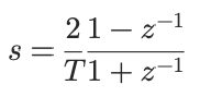
Substitute the transformation formula
Simplify to obtain H(z)
Properties:
No aliasing (provides one-to-one mapping)
Stable systems remain stable
Widely used in digital filter design
Bilinear Transform Formula
FIR vs IIR stability
FIR filters are always stable
Stability can be difficult to judge for IIR filters - quantisation error can cause instability
FIR vs IIR order
FIR filters need to a higher order for a given filter specification (higher order for a steeper roll off)
FIR vs IIR phase response
FIR filters can be designed with a perfectly linear (non-distorting) phase response