medical imaging exam
1/67
There's no tags or description
Looks like no tags are added yet.
Name | Mastery | Learn | Test | Matching | Spaced | Call with Kai |
|---|
No analytics yet
Send a link to your students to track their progress
68 Terms
function of xray table and bucky
supports patient and permit xray transmission
robust
radiolucent
easily cleaned
hard to damage - ie scratch
height adjustable and floating
include time for detector, grid and aec (automatic exposure control)
tube supports
mechanical framework which holds the xray tube in
permits easy manipulation flexibility and stability of position
ceiling/overhead - allows longitudinal, transverse and vertical movement
floor to ceilding (or wall) - allows longitudinal and vertical movement
exposure chart details are specific
name of projection
kVp
mAs or mA and s
SID - source to image distance
grid or non grid
what happens when you press the xray exposure button - first pressure
anode begins to rotate
cathode heats to release electrons
what happens when you press the xray exposure button - second exposure
electrons bombard anode
xrays produced
timer circuit “breaks”
cephalad
towards head
caudad
towards feet
what is the issue with the image
low density
what is the issue with the image
high density
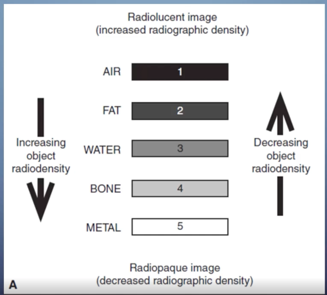
higher object density leads to high radiographic density on an image
this is because if the object is more dense it attenuates the beam more - then we say that something that appears whiter on a film has a lower radiographic density
air and fat is radiolucent and less dense - attenuates the xray beam less so comes up on the xray as black and is radiographically dense
contrast
the difference in density on adjacent areas of a radiographic image
high contrast (short scale)
greater difference between adjacent densities = more black and white
low contrast (longer scale)
lesser difference between adjacent densities = more shades of gray (not beneficial)
spatial resolution
the ability of an imaging system to differentiate between two near-by objects
sharpness, detail, definition
differences between DR and CR system
DR is sharper and has improved spatial resolution
kVp
kVp controls the penetrating strength or the quality
the higher the kVp, the more likely the xray beam will be able to penetrate through thicker or more dense material
a good kVp results in sufficient penetration and contrast
to high kVp = loss of contrast
too low kVp = lack of penetration
mAs
controls the amount of xray photons or the quantity
the product of tube current, mA, and exposure time, s
the control pannel provides the highest safe mA for the shortest exposure time
too low mAs = insufficient detail and too bright (low density)
too high mAs = increased dose and too dark (high density
lattitude
the range of an xray exposure that delivers a density in the useful range for diagnostic radiography
wider range allows for errors, but leads to does creep
50% below ideal exposure = quantum mottle
for CR 200% above ideal exposure = contrast lost or burnout
for DR 400% above ideal exposure = contrast loss or burnout
with DR even if you are incorrect with the kVp and the mAs the image is still quite good - more room for error
new machines also have post image abilities to fix an image if it is bad
this can sometimes be a disadvantage as once you take an image, realise it is faulty, you cannot figure out if you over exposed the patient or under exposed them as the image seems normal
quantum mottle
if we double the exposure we get contrast loss and burnout
digital exposure manipulation
the computer algorythm will undergo automatic rescaling to produce the best possible image
however, once again
quantum mottle/noise if exposure is too low ~ 50%
loss of contrast/burn out if exposure too high ~ 200-400%
15% rule for contrast
ncrease kVp by 15% and halve mAs
lower contrast
same exposure
lower dose
decrease kVp by 15% and double mAs
higher contrast
same exposure
higher dose
15% rule for penetration
a 15 percent increase in kVp will result in doubling the exposure
grids
transmit direct xrays, absorb scattered xrays
increase resolution and contrast
require an increase in mAs
body habitus
thicker tissue requires greater exposure
muscle requires greater exposure than fat
need a higher exposure in kVp and mAs for xraying people with more fat or muscle over the bone
paediatric exposure
lower mAs to reduce exposure and motion - kids move around so lower the time of exposure
check exposure chart
consider non-grid technique
adult AP abdomen 81/10
baby AP abdomen 65/2
casts
if you are imaging someone wearing a cast increased exposure is needed
fibreglass
increase mAs by 20-30 mAs
medium plaster
increase mAs by 50%
larger plaster
increase mAs by 100%
additive diseases
increase the attenuation of the beam
anatomically radiodense
atelectasis
pneumonia
metastases
destructive diseases
decrease attenuation of the beam
more xrays getting through to the detector
osteoporosis
emphysema
multiple myeloma
post processing
manipulation of the radiograph after aquisition
windowing - brightness and contrast
image annotation
image orientation
magnification
post processing collimation
image stitching
measurement
printing
usually DR and CR can do alot of these
however we should do them to make sure
post processing collimation - masking or shuttering
eliminate the ambient light around the image improving resolution and contrast
does not change dose
edge enhancement or high pass filtering
increases contrast, enhances edges
smoothing or low pass filtering
averages out neighbouring pixels, reduces noise and contrast
finger series
PA
oblique
Lateral
PA finger critique
no rotation of the digit
fingernail centered over distal phalanx
no soft tissue overlap
soft tissue and boney trabeculation
open IP and MCP joint spaces
distal phalanx distal MC
oblique finger critique
45 degree digit rotation
no soft tissue overlap
distal phalanx to distal MC
open IP and MCP joint spaces
soft tissue and boney trabeculation
lateral finger critique
distal phalanx to distal MC
condyles superimposed
clear of other fingers
soft tissue and boney trabeculae
lateral second digit we turn the hand around to reduce magnification from the plate
thumb series
AP/PA
oblique
Lateral
AP thumb critique
no rotation
equal soft tissue each side
from distal phalanx to trapezium
open joint spaces
no overlap
soft tissue and boney trabeculae
lateral thumb critique
condyles of phalanx super imposed
from distal phalanx to trapezium
open joint spaces
no overlap
soft tissue and boney trabeculae
hand series
PA
oblique
lateral
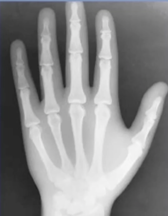
PA hand critique
no rotation
open joints
slightly separated digits
all anatomy distal to radius and ulna
soft tissue and boney trabeculation
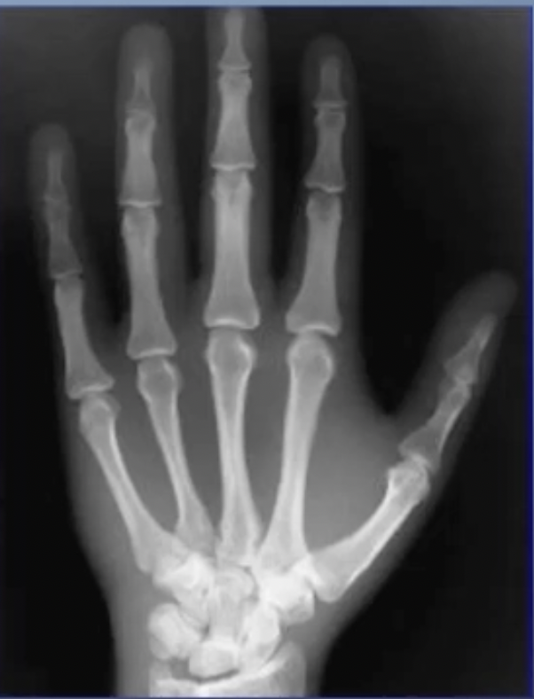
oblique hand critique
minimal overlap of metacarpals 3, 4, and 5
separation of metacarpals 2 and 3
open interphalangeal and MCP joints
digits separate
whole hand
distal radius and ulna
soft tissue and boney trabeculation
lateral hand critique
true lateral position
superimposed metacarpals, phalanges, radius and ulna
phalanges extended
thumb slightly abducted from hand
ball catchers critique
both hands to carpal region
metacarpal heads to separate
MCPs JTs demonstrated
critique vs interpretation
critique
refers to radiographic quality
ie. positioning exposure marker on or off
interpretation
refers to pathology and abnormal appearances
critique 3 step process
classify the image - is it diagnostic or not
determine the cause - is it technical equipment related pathological
recommend corrective action
paceman acronym - positioning, anatomy, collimation, exposures, markers aesthetics, and names
structure of a long bone
most long bones have a diaphasis in the shaft
also an epiphysis at the bottom and a metaphysis
fibrous membrane covering its surface
there is trabeculae in the middle which is quite hollow - in medullary cavity
open fractures
penetrated the skin surface
complete fractures
all the way through the bone
incomplete fractures
not all the way through the bone
complete fractures may include
transverse = straight across the bone
oblique = an oblique line across the bone
spiral = looks like a corkscrew
comminuted = more than two parts to the fracture
incomplete fractures may include
greenstick and fissure
where is the fracture on the bone
proximal, distal, midshaft, etc
diaphysis, metaphysis, epiphysis
intraarticular, extra-articular
land marks? surgical neck of femur, medial malleolus, etc
is the fracture displaced
re the fragments displaced, ie out of alignment
if they are, describe the displacement
the displacement of the distal component in relation to the proximal component
rheumatoid arthritis
subluxations, dislocations, joint space narrowing, cysts, erosions
osteoarthritis
joint space narrowing
sclerotic margins
osteophytes
bony cysts
Scatter radiation
Radiation that has changed direction due to interaction with material
Detrimental to the contrast of an image
Increases the patient dose
Factors effecting the rate of scatter
KVp
Irradiated material
Other sources of scatter include materials beyond the image receptor
Table
Floor
walls
Effects of kVp increased
Increased penetration
Decreased attenuation
Increased scatter
Decreased contrast
with a bigger attenuation material
there is more scatter
Beam restriction
Aperture diaphragms
Cones/cyliners
Collimators
All limit the final beam to a more refined focal point
Adjustable lead shutters - on collimator
The mirror reflects a light to represent the intended irradiated area
The edges of the shutters are bevelled to prevent leakage
Air gap technique
A gap between part and detector
Atleast 15cm
Increased SID to decrease magnification - have to do this
Means we have to use a higher exposure
Useful for horizontal ray hips
Some of the scatter is detoured away from hitting that detector
Good for horizontal ray views of the hip
Post processing collimation
Performed after image acquisition
No patient dose reduction
Why a grid?
To decrease scatter and increase image contrast/quality
better contrast and resolution
Radiographic grids
Transmit direct xrays, absorb scattered xrays
Thin strips of lead (grid strips) attenuate the beam, separated by:
An interspace material - aluminium - which do not
Parallel grids
Linear or crossed
Lead and interspace run parallel
focussed grids
Linear or crossed
Lead and interspace angled from centre