PSAD Merged
1/166
There's no tags or description
Looks like no tags are added yet.
Name | Mastery | Learn | Test | Matching | Spaced | Call with Kai |
|---|
No analytics yet
Send a link to your students to track their progress
167 Terms
Resultant of a Force System: Magnitude and Direction
R = √(Rx2 + Ry2)
Θ = tan-1(Ry / Rx)
α is angle wrt x-axis
Moment about a Point
M = Fd
Squared Property of Parabola (Parabolic Cable)
d12 / h1 = d22 / h2
d = distance from lowest point to support
h = height of supports from lowest point
Parabolic Cable: Minimum and Maximum Tension
Tmin = (w dmax2 / 2 hmax)
Tmax = √((Tmin)2 + (w dmax)2)
Length of Catenary Cable
S = (T0 / W0) sinh(W0 x / T0)
Catenary Cable: Tension at any Point
T = T0 cosh(W0 x / T0)
Catenary Cable: Vertical Distance of Lowest Point to any Point of the Cable
y = (T0 / W0) [cosh(W0 x / T0) - 1]
Friction Force
Ff = µs N (static friction)
Ff = µk N (dynamic friction)
Angle of Friction
tanΘ = F / N
when Θ = α, tanα = µ = F / N
Belt Friction
T2 / T1 = eµß
T2 > T1
ß = subtended angle in radians
Rectangle: Area, Centroid, Moment of Inertia
A = bh
Centroid = (b/2, h/2)
Ix = bh3 / 12
Iy = hb3 / 12
Triangle: Area, Centroid, Moment of Inertia
A = bh / 2
Centroid = (b/3, h/3)
Ix = bh3 / 36
Iy = hb3 / 36
Circle: Area, Centroid, Moment of Inertia
A = πr2 = πd2 / 4
Centroid = (d/2, d/2)
Ix = πd4 / 64
Iy = πd4 / 64
Quarter Circle / Spandrel
A = πr2 / 4
Centroid = (4r/3π, 4r/3π)
Ix = 0.055r4
Iy = 0.055r4
Rectilinear Motion: Uniform Motion
s = vt
a = 0
Rectilinear Motion: Uniformly Accelerated Motion
a = constant
v = v0 ± at
s = v0 t ± at² / 2
v² = v0² ± 2a (x - x0)
Rectilinear Motion: Instantaneous vs. Average
Instantaneous Velocity: v = dx / dt
Instantaneous Acceleration: a = dv / dt = d2x / dt2
Average Velocity: vave = (x - x0) / (t - t0)
Average Acceleration: aave = (v - v0) / (t - t0)
Rectilinear Motion: Free Fall
v2 = v1 ± gt
v22 = v12 ± 2gy
y = v1t ± gt2 / 2
t = √(2y / g)
ymax = v12 / 2g
(+) - upwards
(-) - downwards
Projectile Motion
v0x = v0 cosΘ
v0y = v0 sinΘ
x = v0x t
t = v0 sinΘ / g + √(2hmax / g)
hmax = ymax + h
ymax = v02sin2Θ / 2g
Projectile Motion: General Formula for height of projectile
y = xtanΘ - gx2 / (2v02cos2Θ)
Rotational Motion
ω = dΘ / dt
α = dω / dt
s = rΘ
v = rω
Rotational Motion: Acceleration Components
aT = αr
aN = ω2r = v2 / r
a = √(aT2 + aN2)
Work
W = F d
Power
P = W / t
Gravitational Potential Energy
PE = m g h
Spring Potential Energy
PE = kx2 / 2
Kinetic Energy
KE = mv2 / 2
Linear Momentum and Impulse
p = m × v
Conservation: mv1 = mv2
J = F × t
Coefficient of Resitution
e = - (vB2 - vA2) / (vB1 - vA1)
Particle Kinetics: Centripetal Force
Fcf = mv2 / r
Particle Kinetics: Banked Curves
Friction is Considered: tan (Θ + Φ) = v2 / gR
Car is Slipping: tan (Θ - Φ) = v2 / gR
Design Angle of Banking: tan (Θ) = v2 / gR
Axial Stress
σ = P / A
(P = axial load, A = cross-sectional area where axial load is applied)
Axial Strain
ε = δ / L = σ / E
(δ = deflection/change in length, L = original length, E = modulus of elasticity)
Modulus of Elasticity
E = σ / ε
Axial Deformation/Deflection
δ = PL / AE = σL / E
Thermal Deformation
δT = αLΔT
(α = Coefficient of Thermal Expansion)
Shear Stress (General)
τ = V / As
(V = Shear Force, As = sheared area)
Shear Strain
γ = δs / L
Modulus of Rigidity
G = δs / γ
Shear Deformation
δs = VL / AsG
Bearing Stress
σb = Pb / Ab
Cylindrical Thin-Walled Pressure Vessels
Tangential/Hoop: σT = pD / 2t
Longitudinal/Axial: σL = pD / 4t
(p = internal pressure, D = diameter of vessel, t = thickness)
Spherical Thin-Walled Pressure Vessels
σ = pD / 4t
(p = internal pressure, D = diameter of vessel, t = thickness)
Torsional Shear Stress
τ = Tr / J
(T = torque, r = radius of curvature, J = polar moment of inertia)
Torsion: Angle of Twist
θ = TL / JG
(T = torque, L = length, J = polar moment of inertia, G = modulus of rigidity)
Polar Moment of Inertia
J = Ix + Iy
For circular solid shafts: J = πD4 / 32
For circular hollow shafts: J = π(Do4 - Di4)
Helical Springs: Approximate Maximum Shear Stress
Ss = 16PR/πd3 * (1 + d/4R)
(P = load applied, R = spring radius, d = diameter)
Helical Springs: Deformation
δ = 64PR3n / Gd4
(n = number of turns, G = modulus of rigidity, R = spring radius, P = load applied, d = diameter of wire)
Flexure: Bending Stress
fb = My / I
(M = maximum moment, y = distance of point from NA, I = moment of inertia)
Flexural Shear Stress
fv = VQ / Ib
(V = maximum shear force, Q = A’y’, I = moment of inertia, b = width at section)
Note: A’ = area above/below NA, y’ = distance from centroid of A’ to NA
Shear Flow
q = VQ / I = fv b
(V = maximum shear force, Q = A’y’, I = moment of inertia)
Shear Connector
s = RI / VQ = R/q
(s = pitch of shear connector, R = total resistance of connectors within pitch length)
Flexure for Curved Beams
fb = Ey / ρ
(E = modulus of elasticity, y = point from NA, ρ = radius of curvature)
Flexure: Non-homogeneous beams
n = Es / Eb
b → nb
ftransformed = nMc / I
Combined Stresses
σ = ± P/A ± Mc/I
τ = V/A
τ = VQ/Ib + Tr/J
Mohr’s Circle: Sign Convention
Normal Stress: (+) Tension, (-) Compression
Shear Stress: (+) Clockwise, (-) Counterclockwise
Static Determinacy of Beams (Planar)
DI = R - 3 - C
R - external reactions, C - releases
Static Determinacy of Beams (3D)
DI = R - 6 - C
R - external reactions, C - releases
Static Determinacy of Frames (Planar)
DI = R + 3M - 3J - C
R - external reactions, M - members, J - joints, C - releases
Static Determinacy of Frames (3D)
DI = R + 6M - 6J - C
R - external reactions, M - members, J - joints, C - releases
Static Determinacy of Trusses (Planar)
DI = R + M - 3J
R - external reactions, M - members, J - joints
Static Determinacy of Trusses (3D)
DI = R + M - 2J
R - external reactions, M - members, J - joints
Equations of Conditions (C) for Internal Hinge
M = 0; 2 internal reactions (Fx, Fy)
Equations of Conditions (C) for Internal Roller
Fx = 0, M = 0; 1 internal reaction (Fy)
Equations of Conditions (C) for Internal Fixed
3 internal reactions (Fx, Fy, M)
Equations of Conditions (C) for Internal Slider
Fy = 0; 2 internal reactions (Fx, M)
DIM: Moment Equation
EI y” = M
E = modulus of elasticity, I = moment of inertia
DIM: Slope Equation
EI y’ = ∫ M dx + C1
E = modulus of elasticity, I = moment of inertia
DIM: Beam Deflection Equation
EI y’ = ∫ ∫ (M dx) dx + C1x + C2
E = modulus of elasticity, I = moment of inertia
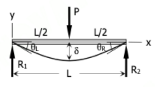
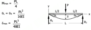
Superposition Method - Simply Supported Beam: Concentrated Load at Midspan
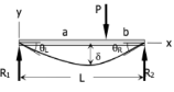
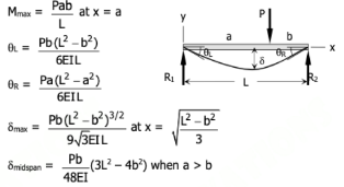
Superposition Method - Simply Supported Beam: Concentrated Load, General
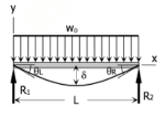
Superposition Method - Simple Beam: Uniform Load over Entire Span
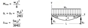
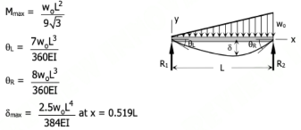
Superposition Method - Simple Beam: Uniformly Varying Load over Entire Span with Zero load at one end
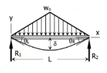
Superposition Method - Simple Beam: Symmetrical Triangular Load over Entire Span
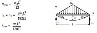
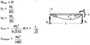
Superposition Method - Simple Beam: Moment Load at Right End
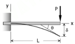
Superposition Method - Cantilever Beam: Point Load at Free End

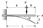
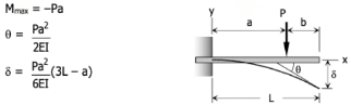
Superposition Method - Cantilever Beam: Point Load, General
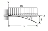
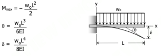
Superposition Method - Cantilever Beam: Uniform Load over Entire Span
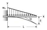
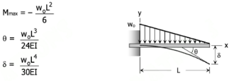
Superposition Method - Cantilever Beam: Uniformly Varying Load over Entire Span with Zero Load at Free End
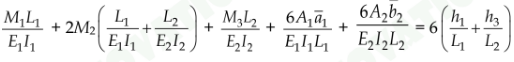
Three-Moment Equation: General
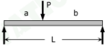
Values of 6Aa/L and 6Ab/L for Point Load, General
6Aa/L = Pa (L2 - a2) / L
6Ab/L = Pb (L2 - b2) / L


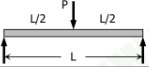
Values of 6Aa/L and 6Ab/L for Point Load at Midspan
6Aa/L = 3PL2 / 8
6Ab/L = 3PL2 / 8
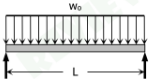
Values of 6Aa/L and 6Ab/L for Uniform Load
6Aa/L = w0L3 / 4
6Ab/L = w0L3 / 4

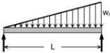
Values of 6Aa/L and 6Ab/L for Triangular Load, 0 at left end
6Aa/L = 8w0L3 / 60
6Ab/L = 7w0L3 / 60

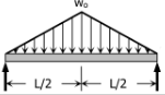
Values of 6Aa/L and 6Ab/L for Symmetric Triangular Load
6Aa/L = 5w0L3 / 32
6Ab/L = 5w0L3 / 32

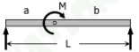
Values of 6Aa/L and 6Ab/L for Moment
6Aa/L = -M/L × (3a2 - L2)
6Ab/L = M/L × (3b2 - L2)

Single Moving Load
Mmax = PL / 4; P loaded at midspan
Vmax = P; P loaded at support
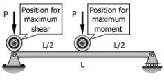
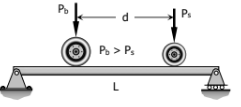
Two Moving Loads
Mmax = (PL - Psd)2 / (4PL)
Ps - smaller load, Pb - bigger load, P - total load
Effective Length Factor, Nomogram Method
Ψ = Σ(EI/L)columns / Σ(EI/L)beams
Moment Distribution Method: Member Stiffness
K = 4EI / L
Moment Distribution Method: Modified Member Stiffness
K = 3EI / L
Moment Distribution Method: Distribution Factor
DF = K / ΣK
Moment Distribution Method: Carry-Over Moment
Fixed: MBA = M / 2
Hinged: MBA = 0
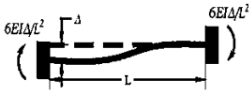
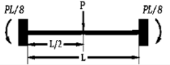
Fixed-End Moment: Concentrated load at Midspan
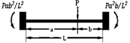
Fixed-End Moment: Concentrated load at any point
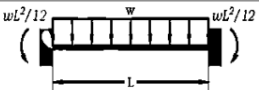
Fixed-End Moment: Uniformly Distributed Load
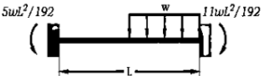
Fixed-End Moment: Uniform Load distributed on half span
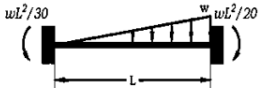
Fixed-End Moment: Load increasing uniformly to one end
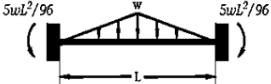
Fixed-End Moment: Load increasing uniformly to center
Fixed-End Moment: Displacement at one end