Radiation Power and Polarisation
 Call Kai
 Learn
Learn Practice Test
 Spaced Repetition
 Match
Match Flashcards
 Knowt Play
1/19

There's no tags or description
Looks like no tags are added yet.
Name | Mastery | Learn | Test | Matching | Spaced | Call with Kai |
|---|
No analytics yet
Send a link to your students to track their progress
20 Terms
Steradian Ω
Unit solid angle
SI unit for 3D angular measurement
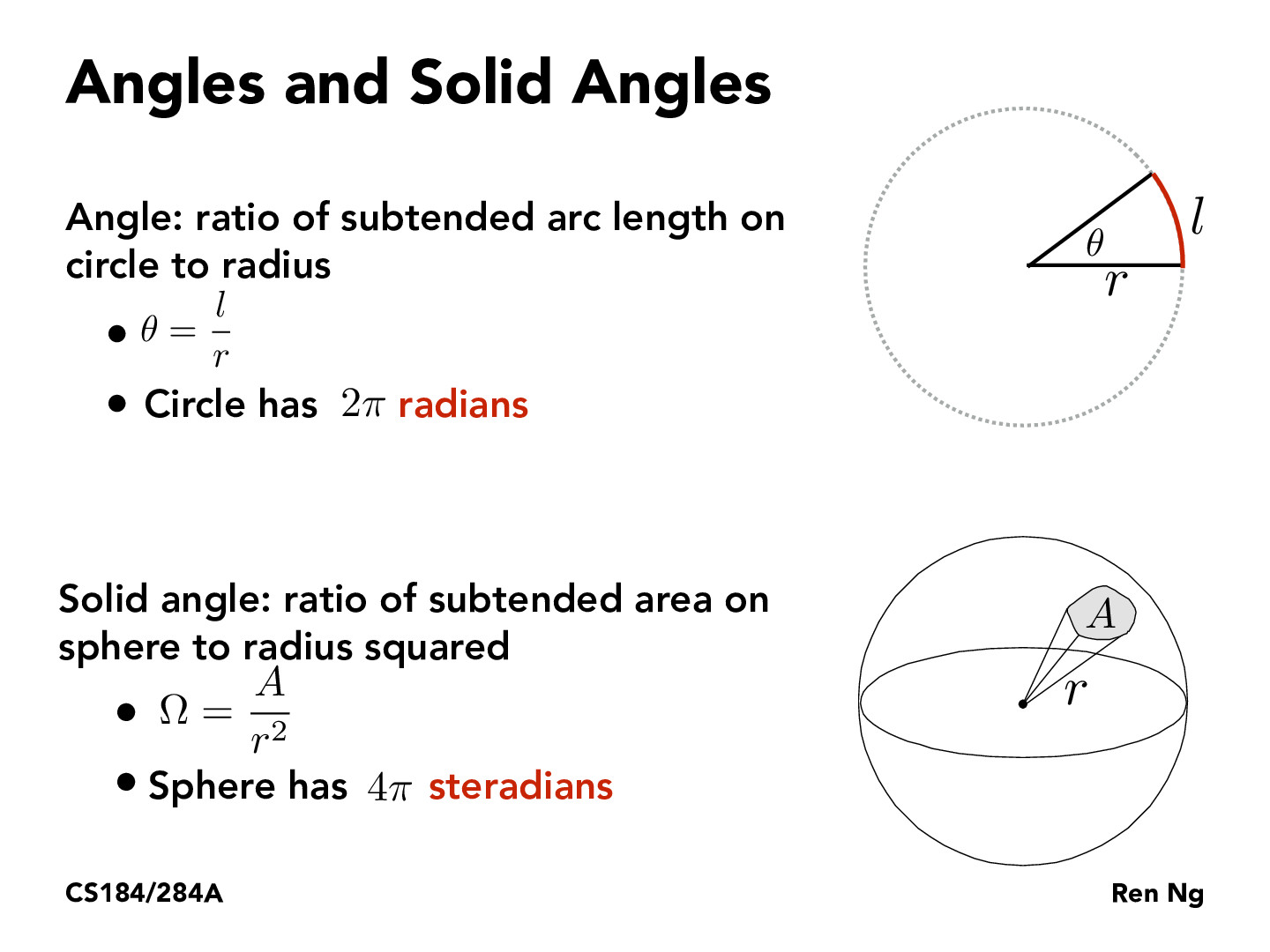
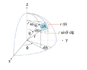
Spherical Coordinates - Area
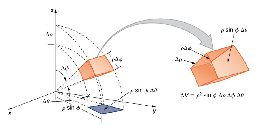
Spherical Coordinates - Volume
Radiation Density 𝑺(𝒓, 𝜽, 𝝓) [𝑾 / 𝒎𝟐]
Power radiated per unit area at distance r
Isotropic Source Example:
𝑺i(𝒓, 𝜽, 𝝓) = Prad / 4𝝅r²
Radiation Intensity 𝑼(𝜽, 𝝓) [𝑾/Ω]
Power radiated per unit solid angle
Independent of distance
Isotropic Source Example
𝑼i(𝜽, 𝝓) = 𝑷𝒓𝒂𝒅 / 4𝝅
D𝐢𝐫𝐞𝐜𝐭𝐢𝐯𝐢𝐭𝐲 𝑫(𝜽, 𝝓)
How well an antenna “beams” energy in a given direction
𝑫(𝜽, 𝝓) = 𝑼(𝜽, 𝝓) / 𝑼i(𝜽, 𝝓) = 4𝝅 𝑼(𝜽, 𝝓) / 𝑷𝒓𝒂𝒅
Maximum directivity usually quoted
𝑫𝒎𝒂𝒙 = 𝑺𝒎𝒂𝒙 /𝑺𝒊
Units in dBi
G𝐚𝐢𝐧 𝑮(𝜽, 𝝓)
Similar to directivity but includes losses
𝑮(𝜽, 𝝓) = 4𝝅 𝑼(𝜽, 𝝓) / 𝑷𝒊𝒏
Radiation Efficiency
𝑮 = 𝜼𝑫
𝜼 = radiation efficiency = 𝑷𝒓𝒂𝒅 / 𝑷𝒊𝒏
Typical values of 0.5 to 0.95
Effective Isotropic Radiated Power
EIRP = 𝑷𝒊𝒏 𝑮
Relative Gain
In many cases antenna radiation patterns are displayed using relative gain
Normalises peak gain to 0dB
𝑮′(𝜽, 𝝓) = 𝑮(𝜽, 𝝓) / 𝑮𝒎𝒂𝒙
Beamwidth Approximation
Approximate relationship between gain and beamwidth
Assuming a directional antenna with 3dB beamwidths given by βx and βy
If all power is assumed to be within 3dB beamwidth then at distance R
𝑃𝑟𝑎𝑑 ≈ 𝑆𝑚𝑎𝑥𝛽𝑥𝛽𝑦𝑅2
Since 𝑆𝑚𝑎𝑥 = 𝑃𝑟𝑎𝑑𝐺𝑚𝑎𝑥 / 4𝜋𝑅²
𝐺𝑚𝑎𝑥 = 4𝜋 / 𝛽𝑥𝛽𝑦
Polarisation
What direction the E field is in (Far Field parameter)
Linear / Circular / Elliptical
Instantaneous Field E(z,t)
Inclination angle of the electric field vector
Linear Polarisation
Tip of E(z,t) traces a straight line
Simplest case when ax or ay = 0
Can also happen when both x and y componenrs are non-zero but are in phsae
Circular Polarisation
Occurs when magnitudes of x and y components are equal and have a phase difference of δ =± 𝜋/2
Elliptical Polarisation
In practice it is difficult to generate perfect circular polarisation and so the tip of E vector traces an ellipse
To measure the ‘ellipticity’ the axial ratio is used:
AR = major axis / minor axis
1 ≤ AR ≤ ∞
Circular → Linear
Polarisation Diversity
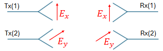
Allows us to transmit 2 separate signals using the same frequency - polarisation diversity
Tx(1) antenna is vertically polarised and Tx(2)
antenna is horizontally polarisedSignal from Tx(1) will be received by Rx(1) antenna
but not Rx(2)
Cross Polarisation
In practice, antennas do not have perfect polarisation
A measure of this is cross-polarisation (XPOL) level – usually in dBs.
Typical XPOL levels are -20 to -40dB below COPOL (co-polar = main polarisation direction)
Left Hand vs Right Hand Circular Polarisation
Transmitter system hardware can be designed to make the wave spin in either counter-clockwise (LHCP) or clockwise (RHCP)
The receiver antenna is built in a way to accept the correct polarisation and reject the other