PFF - Magnetic Materials for Biotechnological Use
1/122
Earn XP
Description and Tags
Yr 3 Chemical Engineering
Name | Mastery | Learn | Test | Matching | Spaced | Call with Kai |
|---|
No analytics yet
Send a link to your students to track their progress
123 Terms
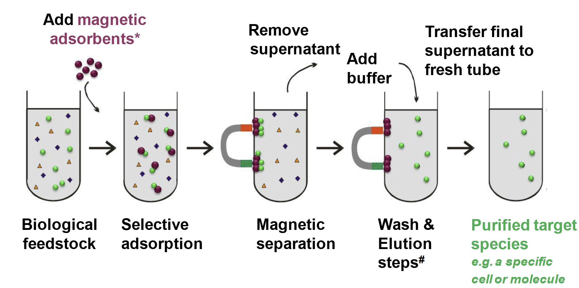
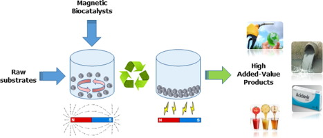
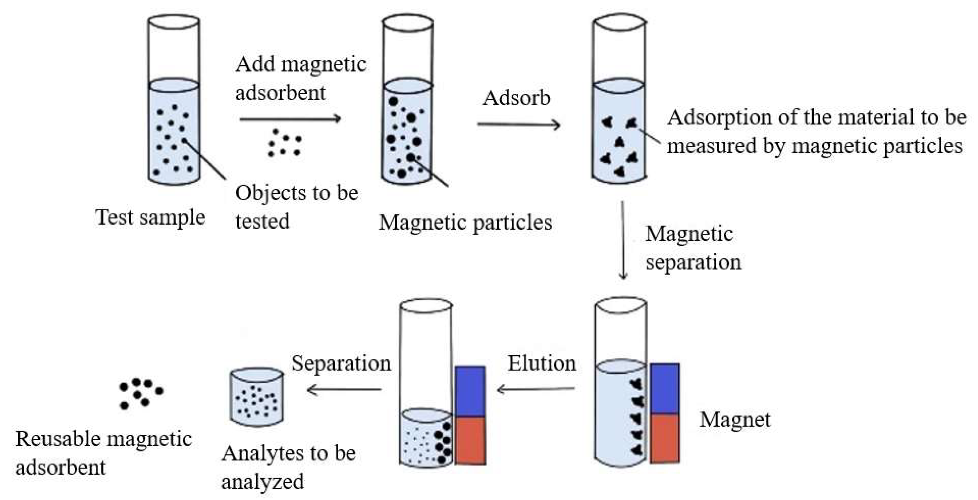
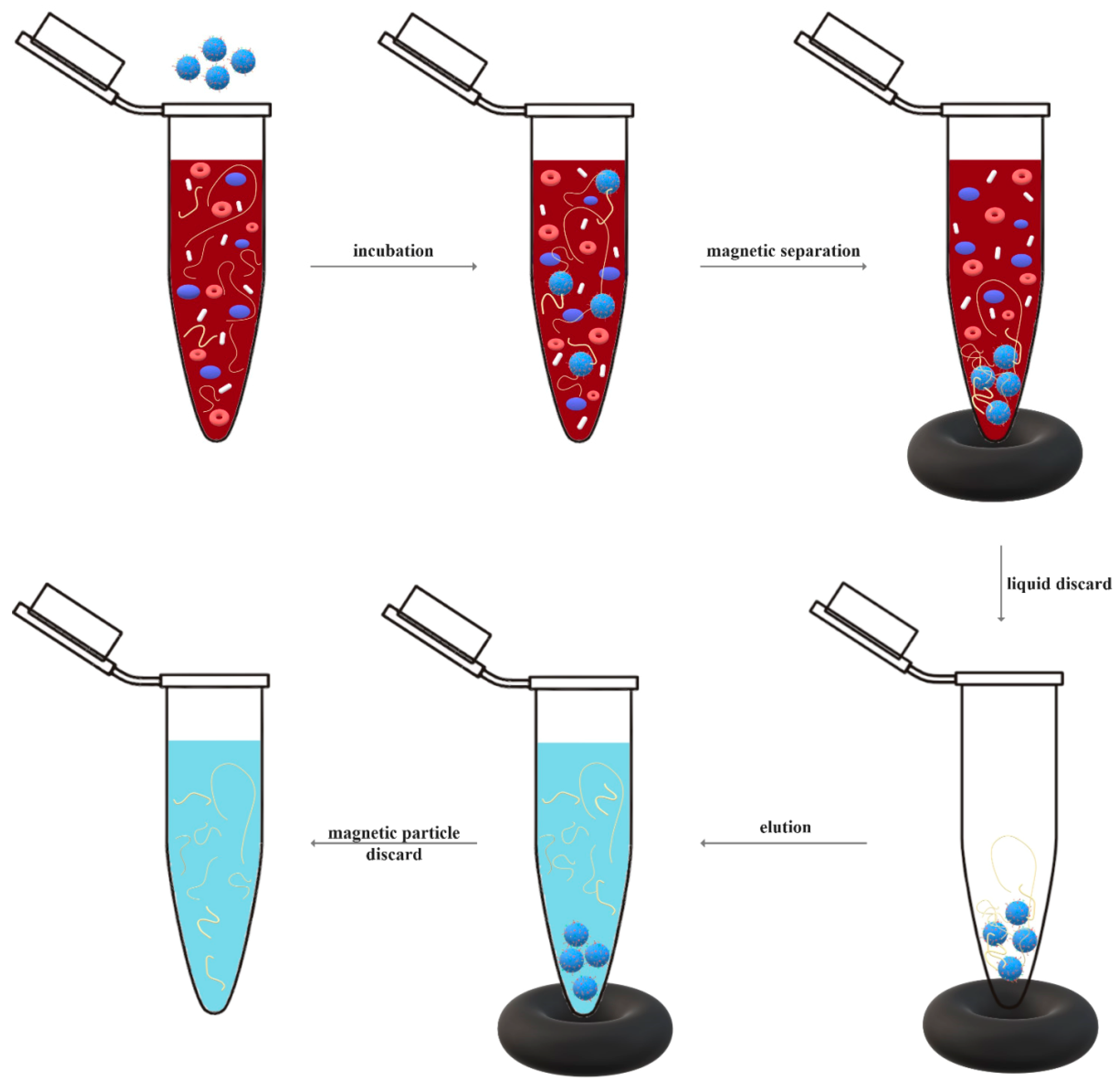
Principle of Bioseparation with Magnetic Supports: Labscale Applications
Biological feedstock
add magnetic adsorbents
Selective adsorption
Magnetic separation
add buffer
remove supernatant
Wash and elution steps
Transfer final supernatant to fresh tube
Purified target species, e.g. a specific cell or molecule
Principle of Bioseparation with Magnetic Supports: Labscale Applications
Magnetic Adsorbents
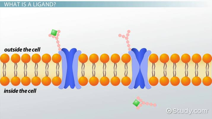
Magnetic particles or beads are functionalised with an appropriate ligand
Principle of Bioseparation with Magnetic Supports: Labscale Applications
Wash and Elution Steps
Numerous cycles of buffer addition
Magnetic separation and supernatant may be required here
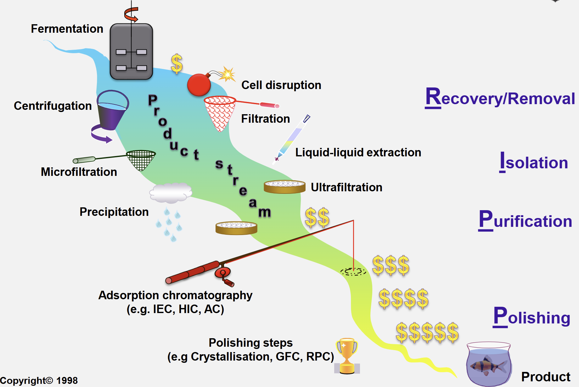
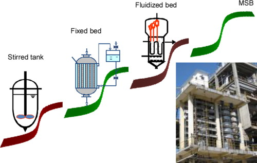
Traditional Approach to Downstream Processing (DSP)
4 Main Steps:
Recovery/removal
Isolation
Purification
Polishing
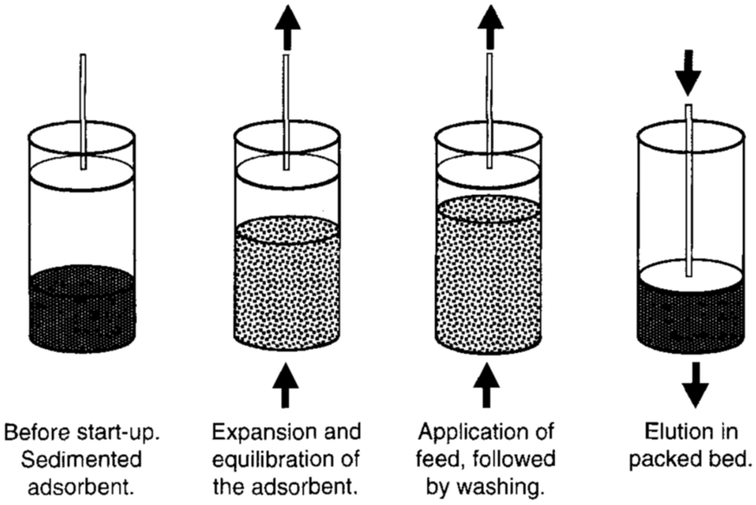
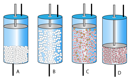
Expanded Bed Adsorption (EBA)
Hybrid of chromatography and fluidised bed
Relies on dense specialised media of defined size and density distribution
Applicable to direct product capture from crude particulate containing feedstocks
(Expanded beds = fluidised beds)
Expanded Bed Adsorption: 3 Gradients
Particle size
for fluidisation stability
biggest at base, smallest at top
Voidage
to allow particles to pass
lowest at base, highest at top
Linear velocity
highest at base, lowest at top
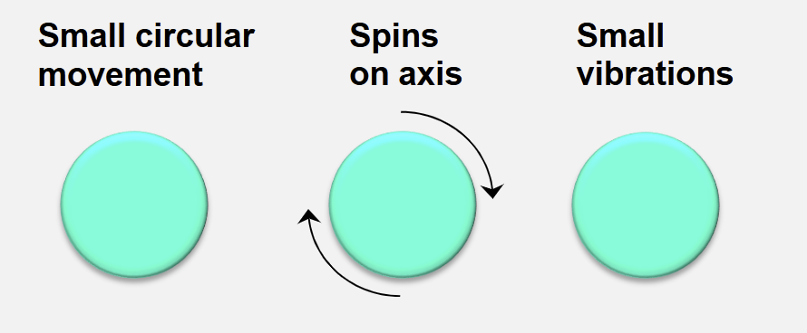
Expanded Bed Adsorption: Particle Movements at Stable Fluidisation
The size of each matrix particle defines its own unique axial position
the beads find their ideal position in the column and at stable fluidisation, small circular movements of adsorbent beads are seen
The bed is stable when only small circulatory movements of adsorbent are observed
the bed expands in a stable and uniform manner
When the bed is stable, no particle within it rises or falls
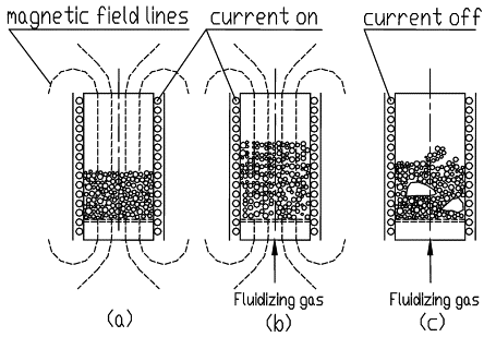
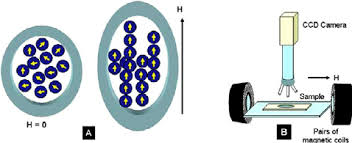
Magnetic Stabilised Fluidised Beds (MSFBs)
Magnetic dipoles induced in the support particles cause them to become spatially fixed, stabilising the bed to form a MSFB
The magnetic dipoles are induced along the field lines, so that particles have a tendency to align vertically and oriented parallel to the flow through the bed
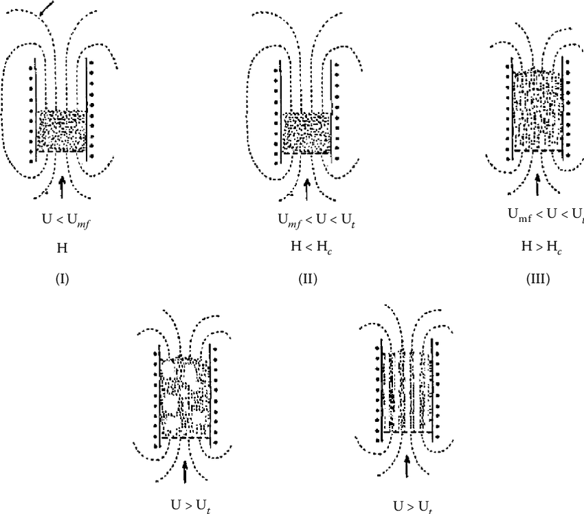
Magnetic Stabilised Fluidised Beds (MSFBs):
Complete Stabilisation
For complete stabilisation to occur, the magnetic interactions between particles must be of sufficient magnitude to counter the fluidising forces, which tend to mix the particles
As particles in the MSFB are essentially motionless, the stabilised condition can easily be determined by visual inspection
Advantages of MSFBs (x4)
Low pressure drop
Resistance to clogging from particulates and colloidal materials in crude feeds
The possibility for continuous counter current operation
Uncoupling bed expansion from fluidisation velocity by controlling the strength of the applied magnetic field
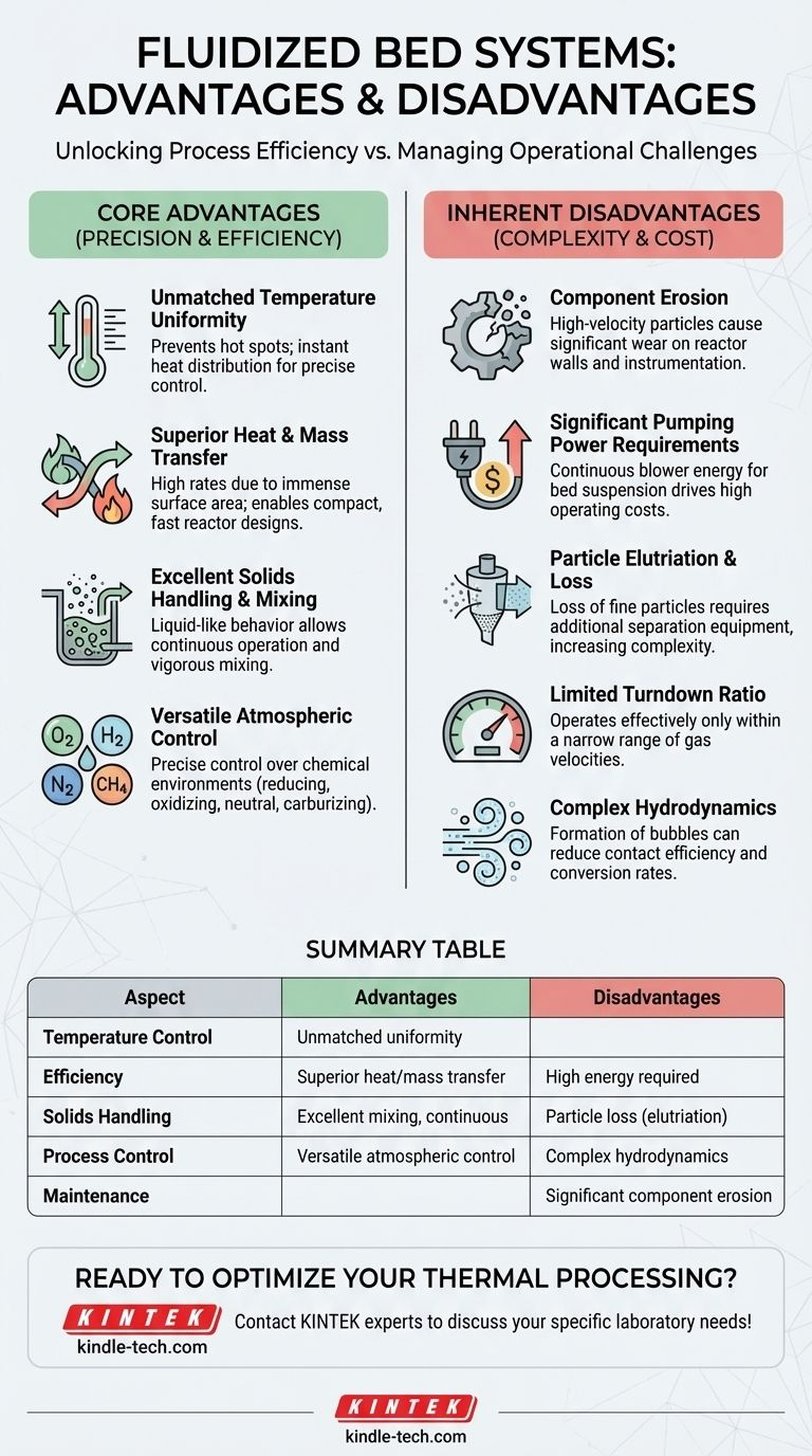
Disadvantages of MSFBs (x2)
Heavily outweighs the advantages:
Channelling between the particle chains resulting in lower mass transfer rates
Added complexity and costs of the magnetic system
Magnetic Separation in Biotechnology
Advantages (x4)
Gentle
Fast
Simple
Compatible with dirty suspensions
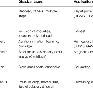
Magnetic Separation in Biotechnology
Disadvantages (x2)
Expensive adsorbents
Only available in small amounts
Applications of High-Gradient Magnetic Separation (HGMS) (x3)
Wastewater treatment
Purification of clays, glass sands and other minerals
Preconcentration/beneficiation of weakly magnetic ores

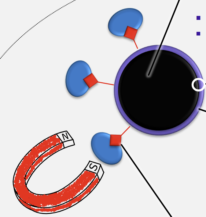
HGMS and Fishing Game Analogy Components (x4)
Rod = magnet
Line = magnetic field
Hook = magnetic support
Bait = immobilised ligand
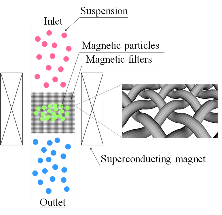
Magnetic Filters for HGMS (x3)
Steel wool
Knit mesh
Regular wire gauze
Blueprint for a Bioprocess Scale Magnetic Adsorbent:
4 Stages
Magnetic core material
Particle coatings
Small scale ligands
Finished product
Blueprint for a Bioprocess Scale Magnetic Adsorbent:
Stage 1 - Magnetic Core Material
Ideally monodisperse < 1 μm and composed of ~ 10 nm crystals
Superparamagnetic properties
Highly textured surface
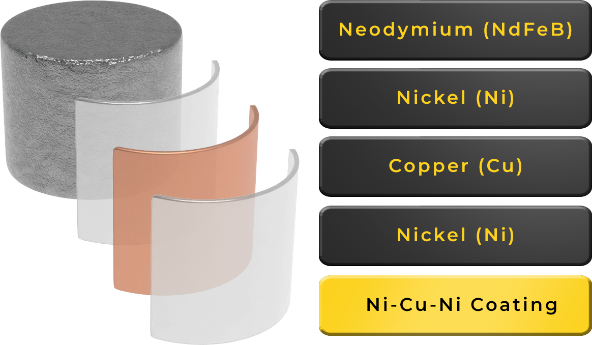
Blueprint for a Bioprocess Scale Magnetic Adsorbent:
Stage 2 - Particle Coatings
Must be very thin
Should not coalesce particles
Neutral hydrophilic exterior surfaces
Easy to derivatise
Protection against corrosion
Blueprint for a Bioprocess Scale Magnetic Adsorbent:
Stage 3 - Small Stable Ligands (Examples)
Ion exchangers
Mixed mode
Pseudoaffinity mimics
Synthetic inhibitors
Blueprint for a Bioprocess Scale Magnetic Adsorbent:
Stage 4 - Finished Product
Cheap
Scalable
Consistent quality
Fine-tuned for separation
Issues to Address for Optimal Use of the Magnetic Support Material
Particle properties
size distribution
density
porosity with respect to target molecule
Magnetic properties
Available surface area for binding
Material and surface chemistry
Ligand
selectivity
how much is required
expense
robustness (especially to cleaning reagants)
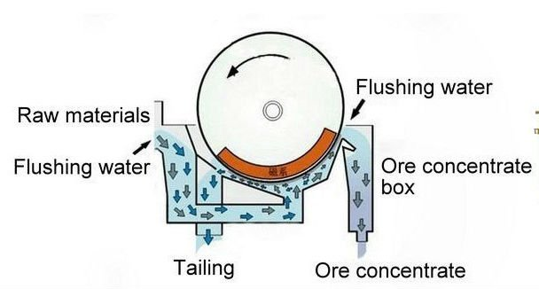
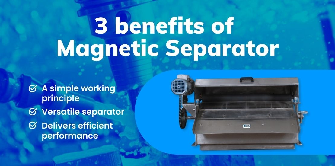
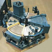
Wet Drum Magnetic Separators
Separates materials by subjecting them to a stationary magnetic field while they are in suspension
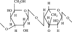
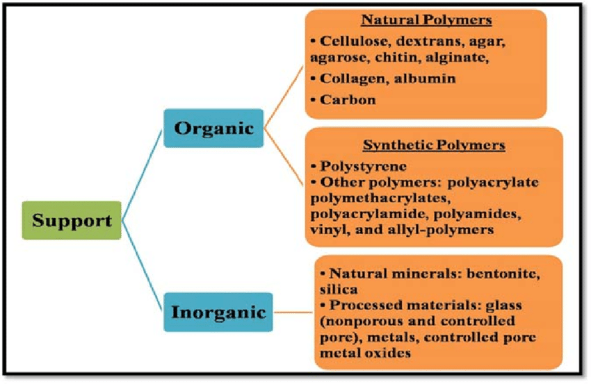
Common Natural Polymers: Agarose
An algal polysaccharide composed of alternating galactose and anhydrogalactose residues
Soluble in hot water and forms rigid meso-macroporous gels upon cooling
Micropores Diameter
< 2 nm
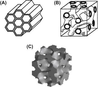
Mesopores Diameter
2 - 50 nm
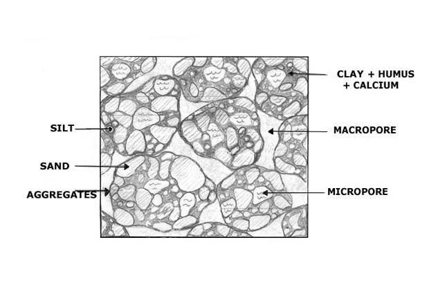
Macropores Diameter
> 50 nm
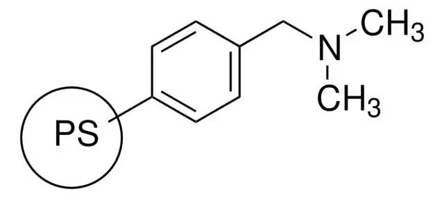
Most Common Matrix Synthetic Polymer:
Poly(styrene-co-divinylbenzene)
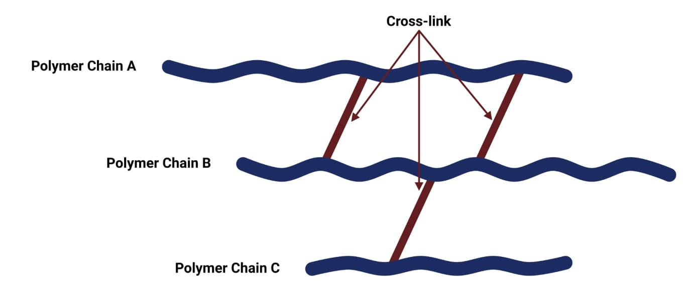
Highly crossed-linked
Cheap
Easy to make small uniformly sized cross-linked polymer particles from styrene and divinylbenzene
Very hydrophobic and unfriendly to proteins
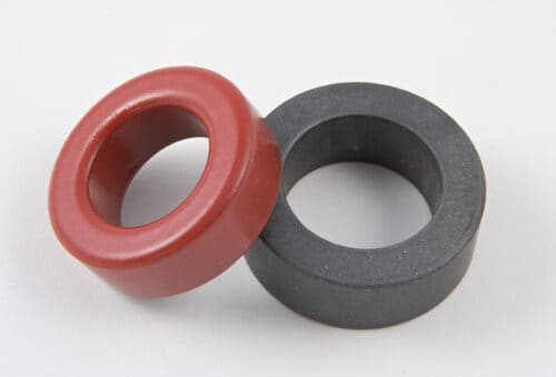
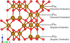
Magnetic Core Materials:
Ferrites
Readily available in large quantities and are characterised by the common chemical structure MO.Fe2O3 where M is typically Fe, Ni, Mn, MnZn or MgCu
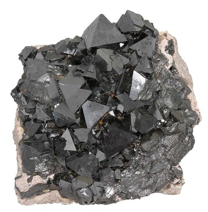
Magnetic Core Materials:
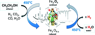
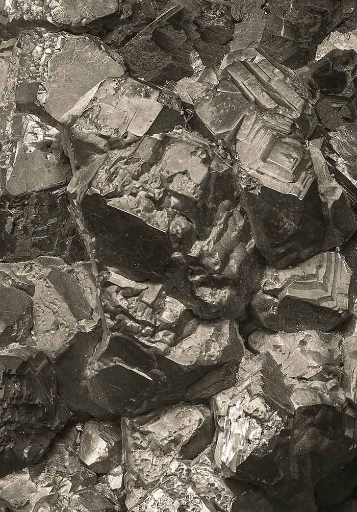
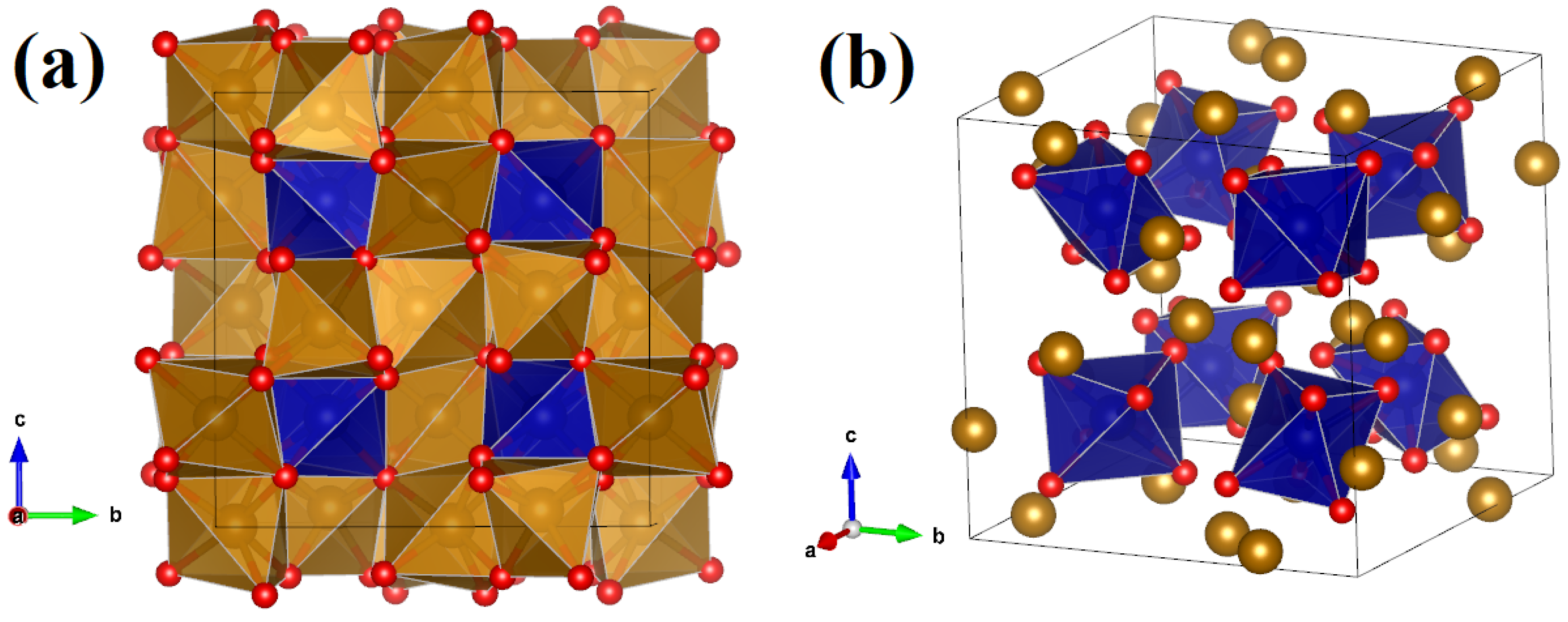
Magnetite (FeO.Fe2O3 or Fe3O2)
Most commonly used
Exhibits higher saturation magnetisation and magnetic susceptibility compared with the only other naturally occurring magnetic iron oxide, maghemite
Magnetic Core Materials:
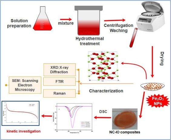
Magnetite Production
Magnetite crystals can be produced by adding alkali to a mixture of Fe2+ and Fe3+ salt solutions
Magnetite crystals rapidly grow and precipitate between pH 9-14
To obtain a pure magnetite requires that reactions are carried out in oxygen free environments to prevent runaway formation of paramagnetic ferroxyhyte δ-FeOOH
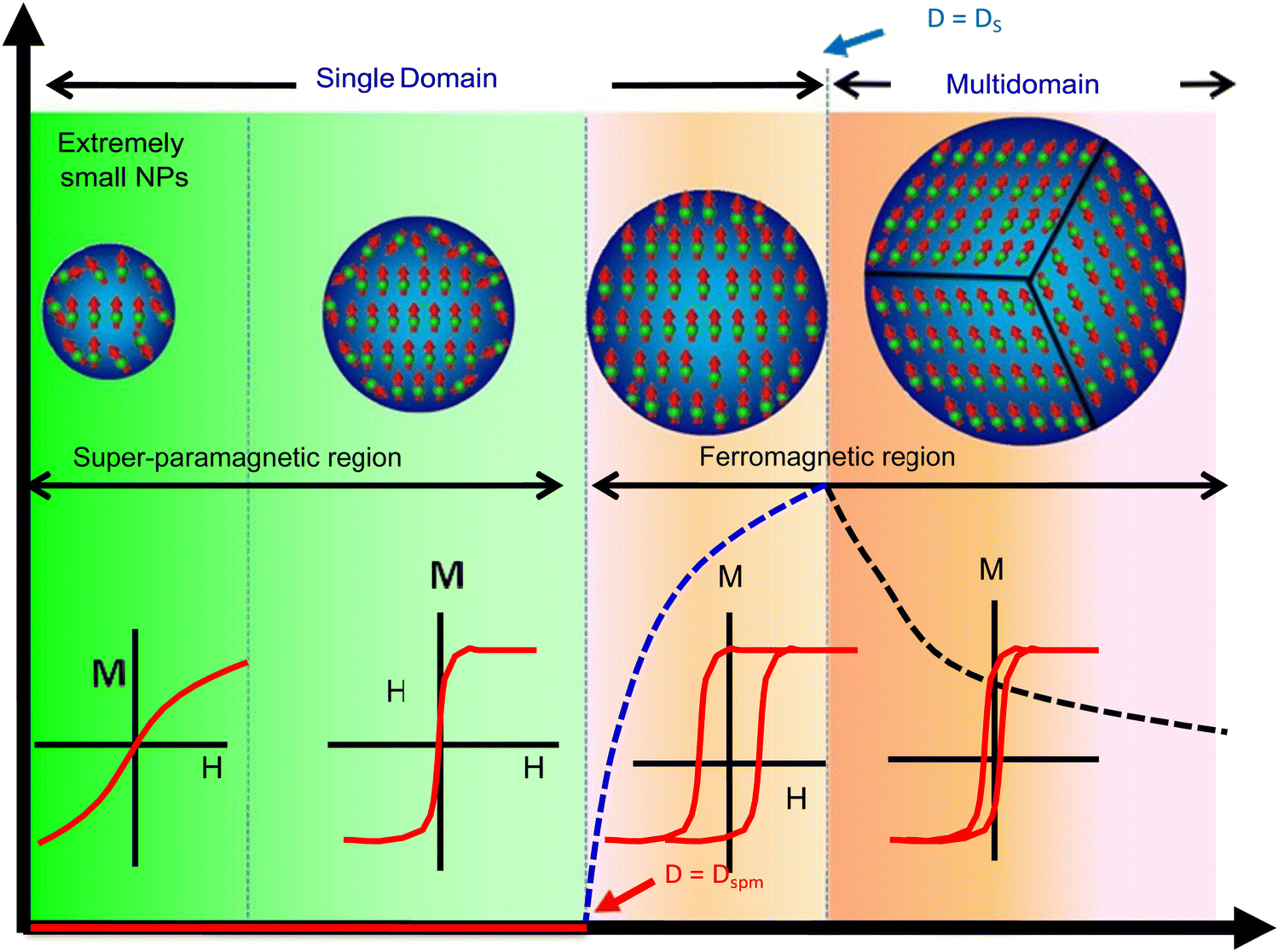
4 Types of Magnetism
Ferromagnetism
Paramagnetism
Diamagnetism
Superparamagnetism
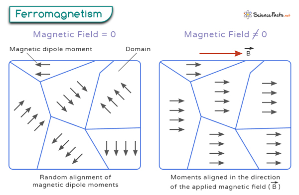
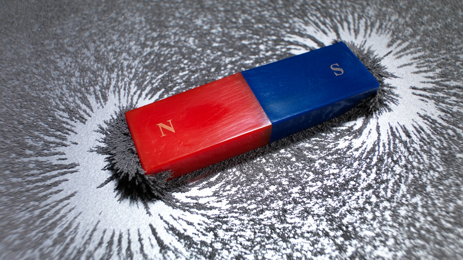
Ferromagnetism
Attracted towards the magnetic field lines when placed in a magnetic field, and the induced force experienced has a strong non-linear dependence on the strength of the magnetic field
As ferromagnetic (e.g. Fe, Co and magnetite) particles can become saturated with magnetic lines of force, a residual magnetism may remain when the applied field is reduced to 0
Ferromagnetic materials consist of microscopic domains, each magnetised in the same direction
Due to their residual magnetism, ferromagnetic materials tend to be unsuitable for repeated use, as they tend to aggregate and form clumps
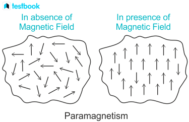
Paramagnetism
Have induced magnetic forces that respond linearly to the applied magnetic field
The magnetic properties are weaker than those of ferromagnetic substances (unless very high magnetic field strengths are applied)
Paramagnetic substances (e.g. Mn and haematite) do not experience any magnetic memory when the field is removed
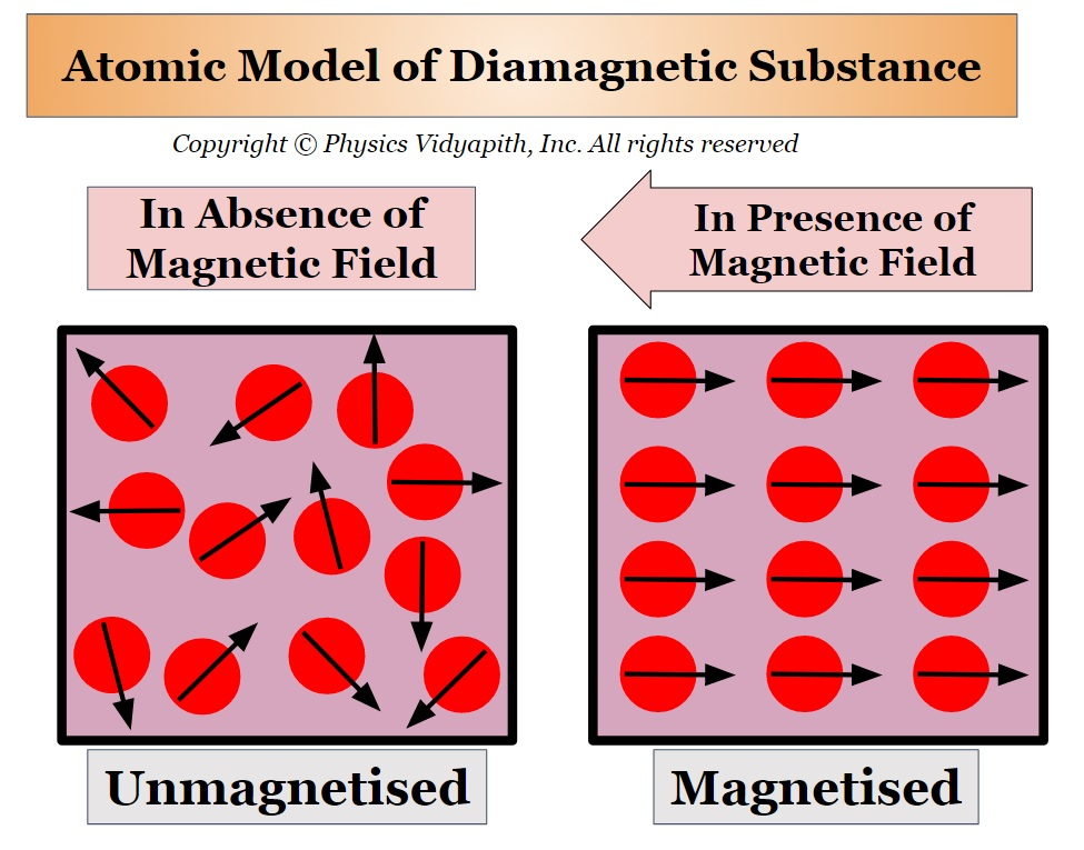
Diamagnetism
Materials that do not have a form of paramagnetism or ferromagnetism exhibit diamagnetic properties
These materials have no unpaired electrons and their magnetic response opposes the applied magnetic field
Examples: copper, silver, gold and bismuth
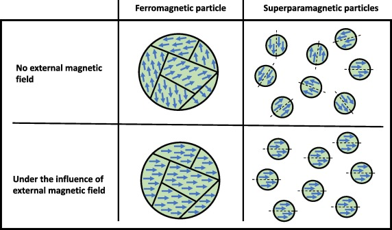
Superparamagnetism
A property of substances whose response to magnetic fields is stronger than normal paramagnetic fields, but still do not exhibit magnetic memory
Properties occur when the crystal size of ferromagnetic substances is sufficiently small to consist of only 1 magnetic domain
The transition point between ferromagnetic and superparamagnetic properties is reported to be ~ 30 nm, i.e. to produce particles with superparamagnetic properties, the crystal size must be < 30 nm
Examples: magnetic iron oxides
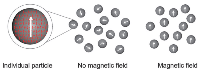
Advantages of Superparamagnetic Particles (x4)
Easy resuspension
Large surface area
Slow sedimentation
Uniform distribution of the particles in suspension media
Advantages of Ferroparamagnetic Particles (x1)
Very strong magnetic properties
Wüstite, FeO
Jet black powder
Feo adopts cubic ‘rock salt’ structure where Fe and O atoms are octahedrally coordinated to one another
Non-stoichiometric iron deficient compounds
Usually prepared by thermal decomposition of iron (II) oxide oxalate in inert atmosphere to avoid formation of ferric oxides

Iron Oxides and Oxyhydroxides:
Colours
Intense colours
Exact colour is very sensitive to partcile size, morphology and internal structure (especially cation substitutions), and a level of purity (presence of impurities)
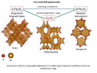
The Common α and γ Phase Iron (III) Oxides:
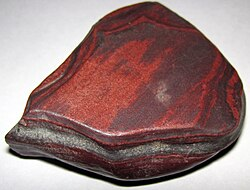
Hematite, α-Fe2O3
Blood red colour in powder form
HCP lattice (trigonal crystal system / hexagonal plate or rhombohedra crystal)
Most common form of Fe2O3
Most stable form of iron oxide in nature
Serves as main feedstock for production of iron, steel and many alloys
The Common α and γ Phase Iron (III) Oxides:
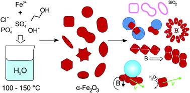
Hematite, α-Fe2O3 Preparation (x2)
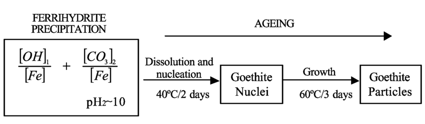
Nucleation and growth of nano-sized ferrihydrite aggregates
Thermal transformations from ferroxyhyte, maghemite and goethite
The Common α and γ Phase Iron (III) Oxides:
Maghemite, γ-Fe2O3
Brown colour
CCP lattice (cubic or tetragonal crystal system / cube shaped crystals)
Metastable
Ferrimagnetic ultrafine particles (<10 nm) are superparamagnetic
The Common α and γ Phase Iron (III) Oxides:
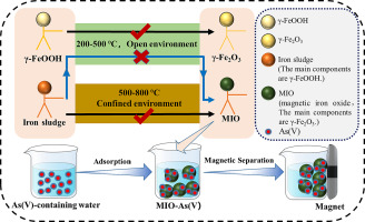
Maghemite, γ-Fe2O3 Preparation (x3)
Thermal Dehydroxylation of γ-FeOOH (lepidocrocite)
Careful oxidation of Fe3O4 (magnetite)
As ultrafine particles by thermal decomposition of iron (III) oxide
The Rare β and ε Phase Iron (III) Oxides:
β-Fe2O3
Mustard yellow colour
HCP lattice (cubic body centred crystal structure)
Metastable phase, converts to α-Fe2O3 at >770 K
The Rare β and ε Phase Iron (III) Oxides:
β-Fe2O3 Preparation (x3)
By reduction of hematite by carbon
Pyrolysis of FeCl2 solution
Thermal decomposition of FeSO4
The Rare β and ε Phase Iron (III) Oxides:
ε-Fe2O3
Metastable, converts to α-Fe2O3 between 770 and 1020 K
Structure and properties intermediate between α-Fe2O3 and γ-FeOOH
Magnetic properties employed in precision data storage electronics
Very challenging to prepare in pure form (contamination with α and γ)
The Rare β and ε Phase Iron (III) Oxides:
ε-Fe2O3 Preparation (x2)
Oxidation of iron in electric arc (very energy intensive for tiny quantities)
Sol-gel precipitation from Fe(NO3)3
Iron Oxyhydroxides
May occur in anhydrous FeOOH or hydrated FeOOH.nH2O forms monohydrate FeOOH.H2O
Also described as: iron (III) hydroxide, hydrated iron oxide, yellow iron oxide
Iron (III) oxyhydroxides occurs naturally as 4 mineral polymorphs denoted by the greek letters: α, β, γ, δ
Iron Oxyhydroxides:
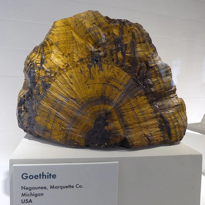
α-FeOOH (Goethite)
Yellow-brown colour used as pigment since prehistoric times
Hexagonal close packed, orthohombic crystal system, needle or lath shaped crystals
Iron Oxyhydroxides:
α-FeOOH (Goethite) Preparation (x2)
Via solution from dissolved partly hydrolysed Fe3+ ions, e.g. Fe(OH2)+, by nucleation and crystal growth
Form ‘green rusts’ by oxidation
Iron Oxyhydroxides:
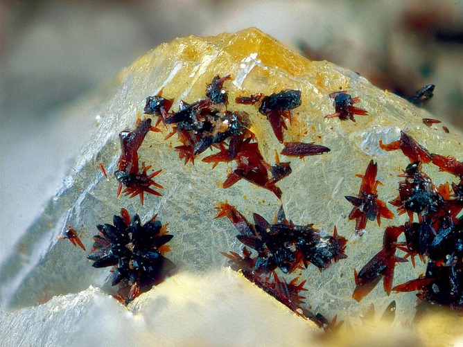
β-FeOOH (Akaganeite)
Rusty brown coloured (III) oxyhydroxide/chloride mineral, i.e. FeO (OH, Cl)
Hexagonal close packed, monoclinic crystal system, star shaped crystals
Iron Oxyhydroxides:
β-FeOOH (Akaganeite) Preparation (x1)
By hydrolysis of FeCl3

Iron Oxyhydroxides:
γ-FeOOH (Lepidocrocite)
Orange colour
Commonly seen as rust on inside of steel water pipes
Cubic close packed, orthorhombic crystal system, needle or lath crystals
Iron Oxyhydroxides:
γ-FeOOH (Lepidocrocite) Preparation (x1)
Oxidation of dissolved Fe2+ directly or via a ‘green-rust’ intermediate
Iron Oxyhydroxides:
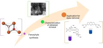
δ-FeOOH (Feroxyhyte)
Brown colour
Forms under high pressure conditions (ocean beds) but readily converts to hematite or goethite
Also found in poorly drained soils and sediments, formed by the rapid oxidation of iron (II) compounds
Hexagonal close packed, hexagonal crystal systems, lath shaped crystals
Iron Oxyhydroxides:
δ-FeOOH (Feroxyhyte) Preparation (x1)
Rapid oxidation of iron (II) salts
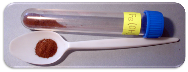
Ferrihydrite, FeOOH.4H2O
Red-brown colour
Widespread hydrated ferric oxyhydroxide mineral
Metastable pressure of more crystalline minerals such as hematite and goethite by aggregation-based crystal growth (transformation generally inhibited in natural systems by surface adsorbed silica)
Hexagonal close packed, hexagonal crystal system, but exhibits poor crystallinity
Only exists as a fine grained and highly defective nanomaterial composed of small sized (~ 3 nm) individual spherical nanocrystals yielding huge surface areas ( > 300 m2 g-1)
Ferrihydrite, FeOOH.4H2O:
Preparation (x1)
Direct precipitation from oxygenated aqueous iron rich solutions at pH > 2
‘Green Rusts’, FeIIx FeIIIy(OH)2
Green-blue coloured FeIIFeIII hydroxy compounds containing a certain amount of non-hydroxyl anion (e.g. Cl-, Br-, F-, I-, SO42-, CO32-)
Layered double hydroxide (LDH) mineral (fougerite) exists in iron containing hydromorphic environments
Exhibits very high sensitivity to oxidation comprises isolation and detection
‘Green Rusts’, FeIIx FeIIIy(OH)2:
Preparation (x3)
Oxidation of aqueous FeII solution
Oxidation/anodic electrolysis of Fe
‘Induced’ hydrolysis from ferrihydrite, goethite or hematite + FeCl2 solution under reducing oxygen depleted conditions
Order of reactivity to transform into green rust is:
ferrihydrite > goethite > hematite
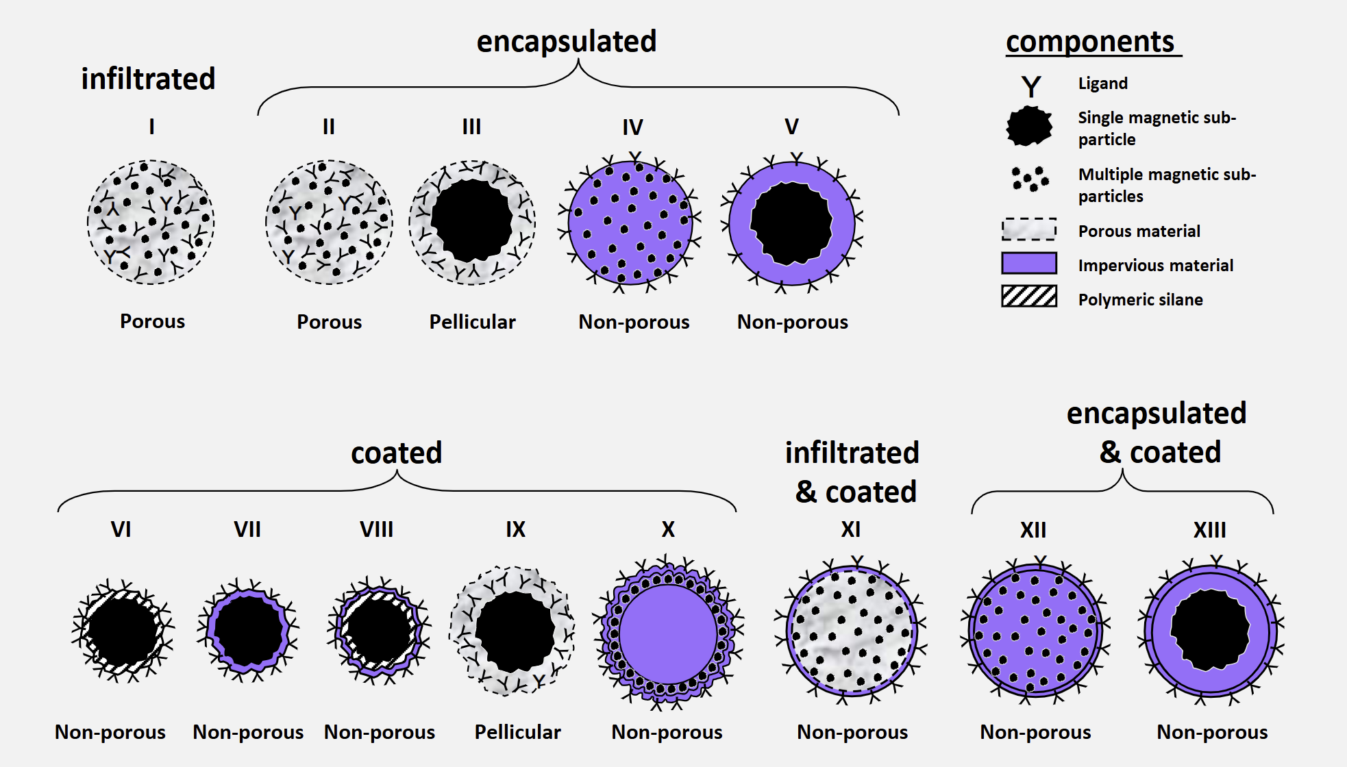
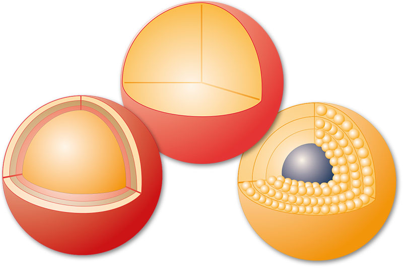
The 13 Magnetic Support Designs Afforded by Infiltration, Encapsulation and Coating Techniques
Infiltrated
porous I
Encapsulated
porous II
pellicular III
non-porous IV
non-porous V
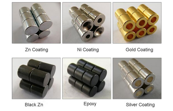
Coated
non-porous VI
non-porous VII
non-porous VIII
pellicular IX
non-porous X
Infiltrated and Coated
non-porous XI
Encapsulated and Coated
non-porous XII
non-porous XIII
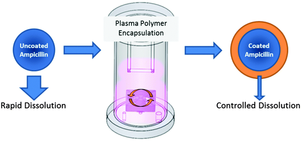
Useful Magnetic Support Materials can be Produced by (x4)
Encapsulation
Infiltration
Coating
Various combinations of ‘encapsulation and coating’ or ‘infiltration and coating’
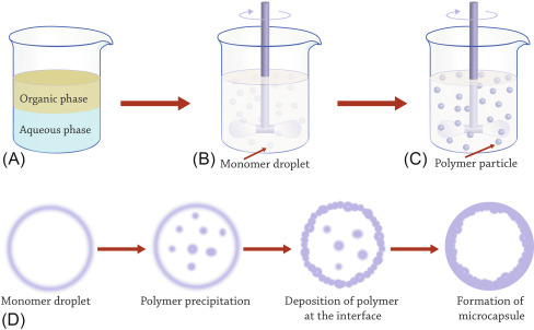
Useful Magnetic Support Materials can be Produced by:
Encapsulation
Encapsulation of solid magnetic elements within natural gels, synthetic resins, or liquid-filled microcapsules
Useful Magnetic Support Materials can be Produced by:
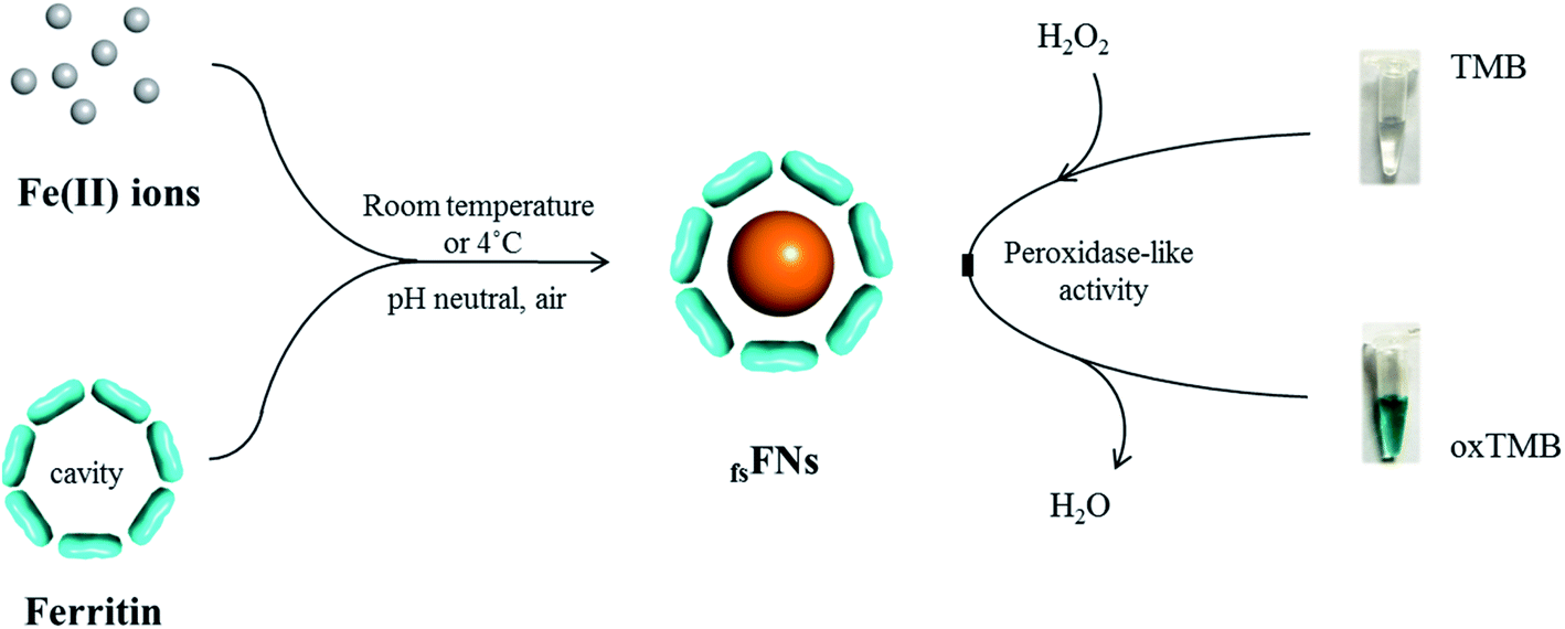
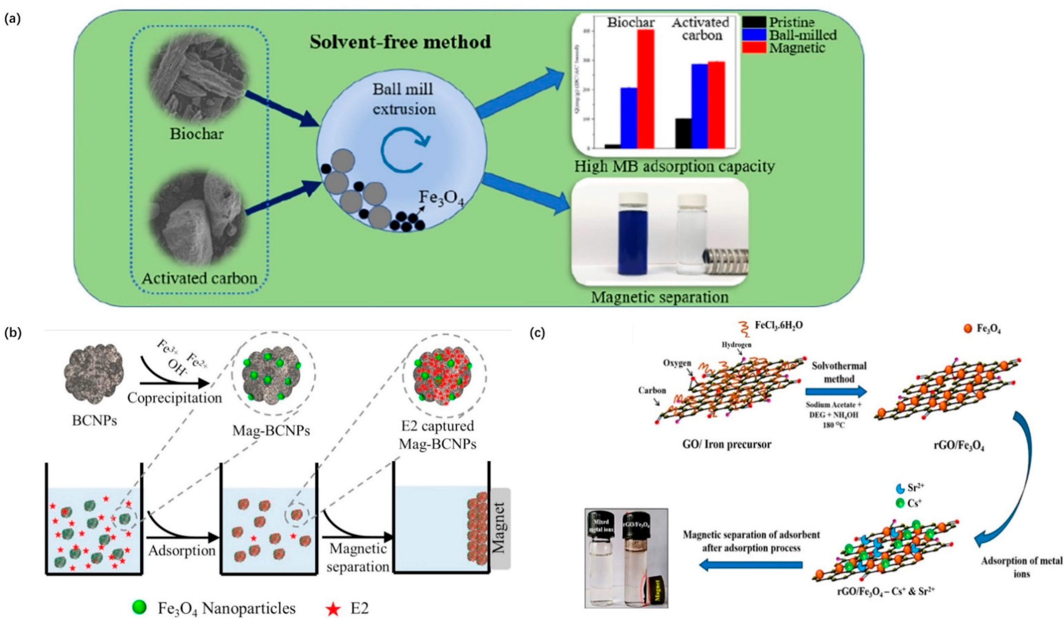
Infiltration
Infiltration of porous supports with fine magnetic sub-particles, or with aqueous mixtures of Fe2+ and other metal ions (e.g. Fe3+, Ni2+, Mn2+, Zn2+, Cu2+) capable of forming magnetic ferrrites when triggered to do so
Useful Magnetic Support Materials can be Produced by:
Coating
Coating magnetic core particles with natural or synthetic polymers or inorganic materials, such as silica
Encapsulation:
Commercial Type II Supports
3 commercially available supports based on encapsulation of magnetite in porous cross-linked agarose
Manufacturers have launched improved materials functionalised with metal chelating agents for immobilised metal affinity adsorption or Protein A for the purification of antibodies
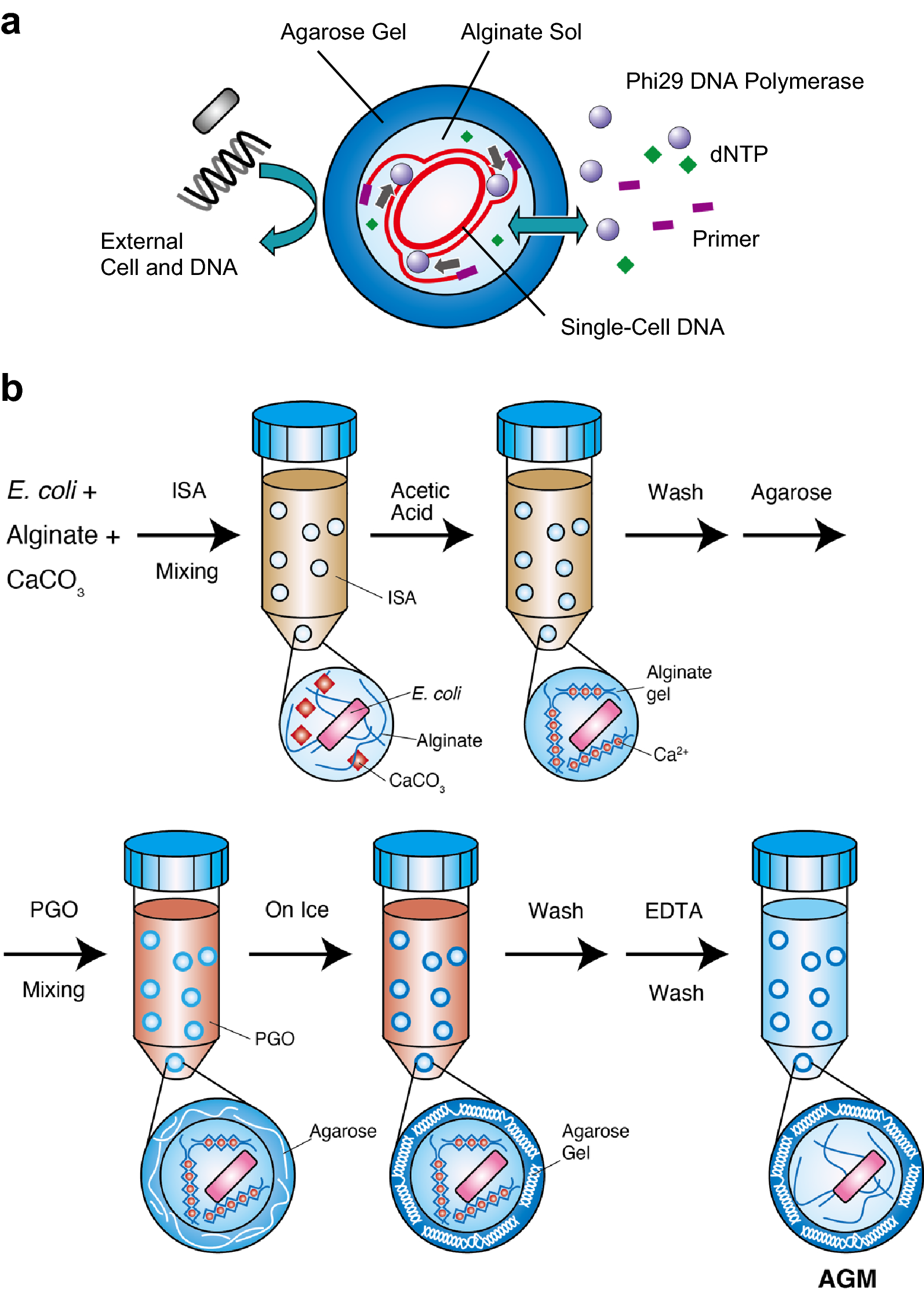
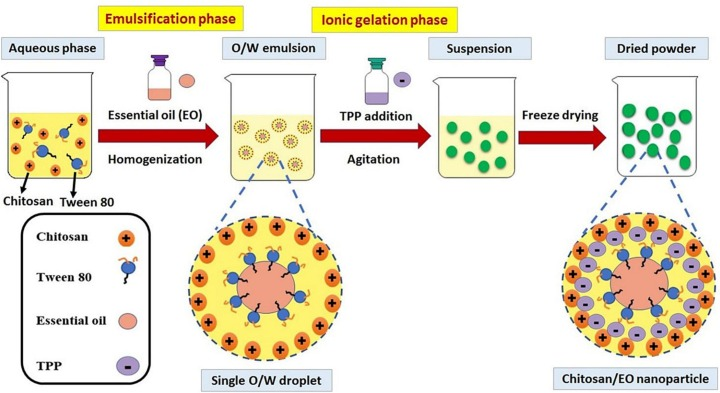
Encapsulation:
Preparation of Beaded Agarose Media
Agarose dissolves in boiling water and forms strong, highly macroporoud gels on cooling
Emulsification of aqueous molten agarose solution
for magnetic versions of beaded agarose media, magnetic particles are added to molten agarose
for expanded bed supports use larger quartz, glass, steel, alloy particles
Stirring conditions determine particle size distribution
Encapsulation:
Agitation
Agitation disprses the solution, forming beaded droplets, whose size is determined by the agitation conditions
Solidified adsorbents are subsequently formed by polymerisation
The porosity of the resulting supports is influenced by the choice of monomer, co-monomer and polymerisation conditions
Most commercial magnetic materials made in this way behave as non-porous supports (types IV and V)
Encapsulation:
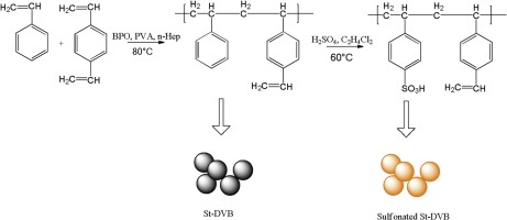
Types IV and V
Polystyrene based magnetic supports
e.g. styrene and divinylbenzene form a highly cross-linked polymer network
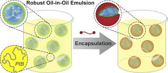
Encapsulation:
‘Water-in-Oil’ Emulsion
‘Water-in-oil’ emulsion techniques have been used to fabricate a great many micron and sub-micron sized magnetic supports encased in various synthetic, natural, and hybrid matrices
Techniques permit the rapid production of primary support particles of types II - V and many appear amenable to low-cost, large-scale manufacturing

Estapor:
IV, (M) V, (EM) V
Estapor IV
extensive range of microspheres based on the Estapor (M) bead
Estapor (M) V
superparamagnetic crystals uniformly distributed in impervious polystyrene bead
Estapor (EM) V
superparamagnetic core particle encased in impervious polystyrene
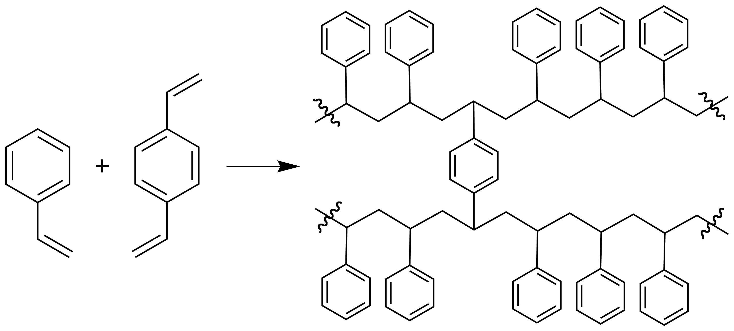
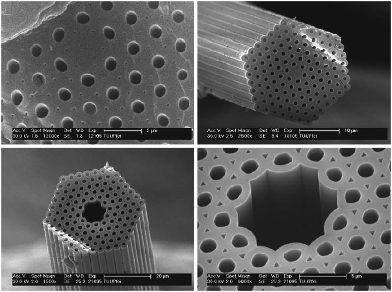
Poly(styrene-co-divinylbenzene) Media:
Based Architecture
Phase separation during polymerisation gives structure resembling a partially fused network of nanoparticles
In most cases, most magnetic versions of beaded polystyrene are made simply by incorporating fine magnetic particles in the pre-polymerisation mix
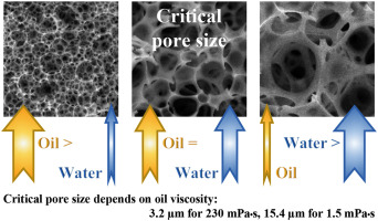
Poly(styrene-co-divinylbenzene) Media:
Effect of Porogenic Solvent on Pore Size
Low solvency porogen, e.g. higher alcohol
High solvency porogen, e.g. aromatic hydrocarbon
Poly(styrene-co-divinylbenzene) Media:
Agarose vs poly(styrene-co-divinylbenzene) Media
Agarose:
porosity 90-98%
medium rigidity
no brittleness
hydrophilic and neutral
10-200 μm
PS-DVB
porosity up to 70%
high rigidity
some brittleness
hydrophobic
needs surface modification
3-30 μm
Poly(styrene-co-divinylbenzene) Media:
General Surface Modification Strategy
Manufacturers modify the surfaces of synthetic hydrophobic polymer based beads in order to make them useful for bioseparation
Create reactive handle, e.g. hydroxyl groups
Covalently attch hydrophilic coating to ‘handles’
Derivatise with ligands usnig conventional coupling procedures
Poly(styrene-co-divinylbenzene) Media:
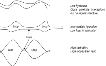
‘Loop and Train’ Surface Modification
The alternative strategy to covalent coupling
An amphilic coating consisting of alternating blocks of hydrophilic segments (loops) and strongly hydrophobic segments (trains) is applied to the polystyrene/divinyl benzene copolymer base matrix to generate a hydrophilic exterior coat which can be cross-linked in place (at its terminii) and functional with ligands
Encapsulation:
Inorganic Support Materials - Advantages (x3)
High mechanical strength
Thermal stability
Resistance to solvent and microbial attack
Encapsulation:
Inorganic Support Materials
Magnetic sub-particles can also be encapsulated within glass, glass ceramics and other inorganic materials
Encapsulation:
Magnetic Glass Particle (MGP) - Preparation (3 Steps)
Mixing a sol consisting of alkoxides of network-forming components (e.g. SiO2, B2O3, Al2O3, TiO2, ZrO2, GeO2) and oxides and salts of other components in an alcohol solution, with magnetic sub-particles
Spray-drying the mixture to gel the sol layers encasing the magnetic cores
Subsequent, high temperature heating in a nitrogen-purged atmosphere yields magnetic cores encased in a substantially pore-free glass
Encapsulation:
Magnetic Porous Glass (MPG) - Preparation
Prepared in a similar way to the manufacture of controlled-pore, glass chromatography adsorbents
Iron oxide-rich alkali metal borosilicate glass is melted at extreme temperatures, under oxidising conditions, triggering the formation and growth of minute crystals of magnetic iron oxides within the glassy matrix
On reducing the temperature, the glass separates to yield islands of iron-rich crystallites, within a continuous, iron-depleted phase of 2 connected, but chemically distinct vitreous phases phases (alkali metal borate and silicate)
After cooling, the glass is then crushed and ball-milled to yield small particles prior to treating with an appropriate mineral acid
Staged Templated Suspension Polymerisation
Small non-porous uniformly sized particles of linear polymers are readily obtained by emulsion polymerisation
The small spheres are used as ‘shape templates’ in processes that not only increase their size many fold, but also introduce pores
A stabilised aqueous disperion of micrometer-size uniform particles is swollen to the target size of the final macroporous product with a combination of solvent, monomers, and cross-linking agents
The swollen particles are then polymerised
The uniformity is retained, but their size is increased considerably, and the presence of solvent during polymerisation leads to desired macroporous structure
In practice, the equilibrium between interfacial energy and swelling forces considerably limits the extent of swelling of the original template
The size of the final bead is no longer determined by the stirring conditions, but by the swelling of the shape-template particles
Infiltration and Coating:
4 Steps
Step 1
small, smooth-surfaced, monodisperse, macroporous, spherical polymer particles (produced in a classical, multistage, ‘activated swelling’ process, employed in the manufacture of high resolution chromatography adsorbents) are covalently modified with oxidative groups, e.g. -NO2, -ONO2
Step 2
these particles are suspended in an aqueous solution of Fe2+ salts
under appropriate conditions (alkaline pH), Fe(OH)2 is continuously transported into the pores where it’s oxidised to form iron oxyhydroxide intermediate
Step 3
on subsequent heating, the iron oxyhydroxide intermediates develop into small crystals of magnetite and/or maghemite, uniformly dispersed throughout the particle
Step 4
the magnetised supports sre then treated with epoxy compounds or synthetic polymers, which fill most of the pores and coat the exterior bead surface to yield an essentially non-porous support (design XI) with low surface area
Infiltration and Coating:
Step 4 Important Features (x2)
Protecting the magnetic elements against possible corrosion, which would result in loss of magnetic properties and possible poisoning of biological molecules by the leakage of soluble Fe3+ ions
Affording convenient means for chemically attaching appropriate ligands to the exterior surface
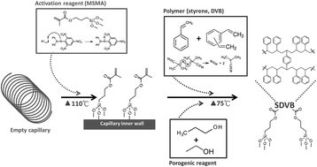
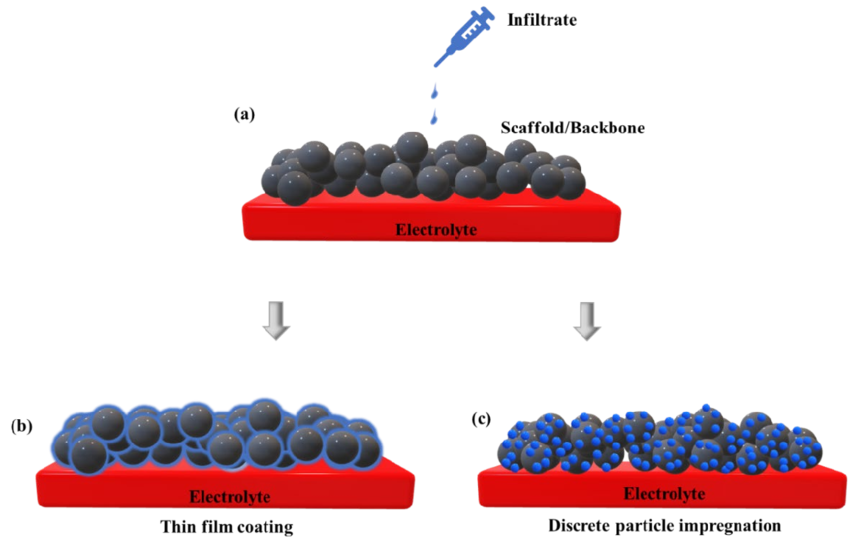
Coating:
4 Different Approaches
Polymer adsorption
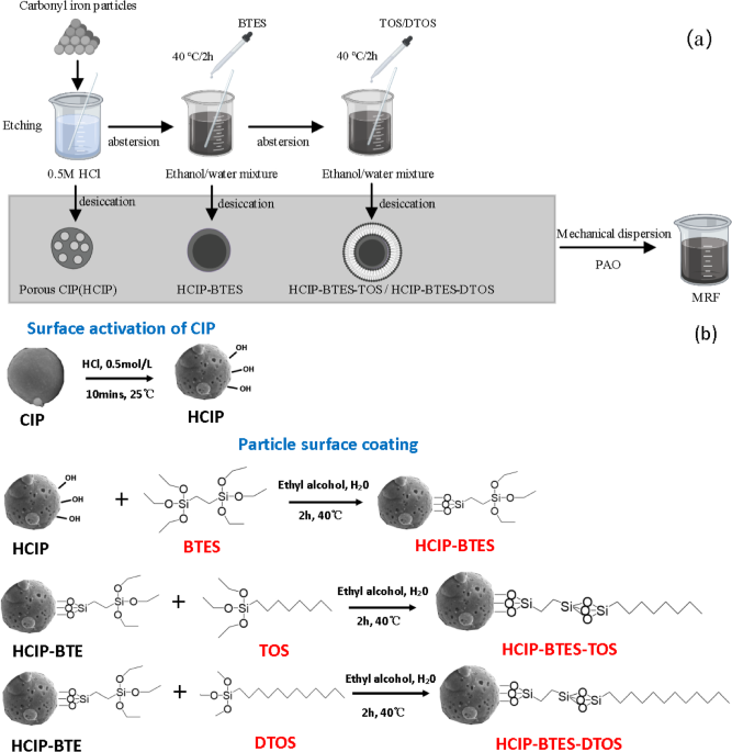
Silanisation
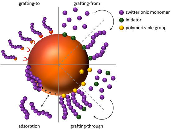
Graft polymerisation
Co-precipitation
Coating:
Polymer Adsorption
Cheap, water-soluble polysaccharide, or synthetic polymers, most often polyamines, such as polyethyleneimine or polyvinyl amine, can be electrostatically adsorbed onto the charged surface of magnetic crystals or particles (design VII) to provide coatings that are easily functionalised
Coating:
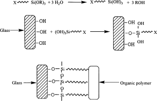
Silane Coupling Agents
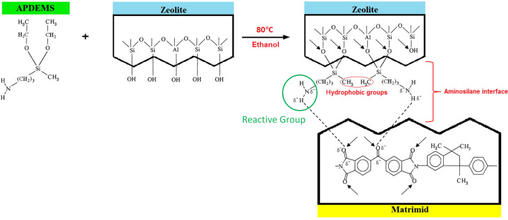
Silane coupling agents are frequently employed to introduce reactive organofunctionalities onto the surface of inorganic materials such as glass, glass ceramics, silica, metals and metal oxides and, when applied to magnetic supports, the desired ligand is then reacted with the introduced organofunctional moiety (most often a primary amine, epoxy or vinyl groups) by standard methods
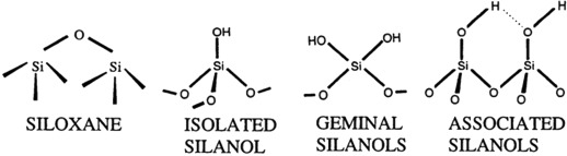
Silane Coupling Agents:
Coupling Mechanism
The coupling mechanism or organofunctional silanes depends on a stable link between the organofunctional group (Y) and hydrolysable groups (X) in compounds with the structure X3SiRY
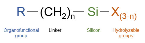
Silane Coupling Agents:
Organofunctional Groups, Y
The organofunctional groups (Y) are chosen for reactivity or compatibility with the organic species
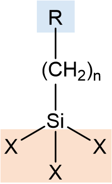
Silane Coupling Agents:
Hydrolysable Groups, X
The hydrolysable groups (X) are merely intermediates in formation of silanol groups for bonding to mineral surfaces
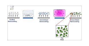
Coating:
Inducing a Polymer Graft (+ 2 steps)
Inducing a polymer graft to grow at the surface of a magnetic particles is an elegant and relatively inexpensive, 2-step approach to manufacturing stably-coated, non-porous magnetic supports:
silane coupling agents, bearing appropriate reactive groups (e.g. vinyl or primary amines) can be employed to prime the particle surface (type VI)
using suitable monomers, it is possible to grow thin, tightly-bound synthetic polymer coats at the primed particle surfaces resulting in type VIII supports
Manufacture of Type VIII Magnetic Base Supports:
Factors Affecting Crystal Size and Magnetic Properties (x4)
Rate of addition and mixing
Reactant concentrations
Temperature
Ratio of [Fe2+] to [Fe3+]
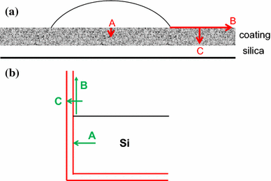
Holding Hydrolysed HOSi Groups at Interface:
Silane Coupling Agents Oxane Bonds
Though oxane bonds of silane coupling agents to some mineral surfaces are easily hydrolysed, it is possible to obtain water-resistant composites of equilibrium conditions can be maintained between a silane-modified polymer and the mineral surface
Holding Hydrolysed HOSi Groups at Interface:
Silane Coupling Agents Equilibrium
Equilibrium conditions are lost if silanol groups are physically removed from the interface
Retention of equilibrium conditions is favoured by proper control of the morphology of the silane-modified coat at the mineral interface
Holding Hydrolysed HOSi Groups at Interface:
Correlated Performance of a Composite with Material Structure at the Interface (x4)
Monomers and oils
Tarry polymers
Flexible or rubbery portions of a polymer
Silanols formed at a rigid interface
Holding Hydrolysed HOSi Groups at Interface:
Correlated Performance of a Composite with Material Structure at the Interface - Monomers and Oils
May be removed physically from the interface as individual links to the surface hydrolysis, thus they are lost for rebonding
Holding Hydrolysed HOSi Groups at Interface:
Correlated Performance of a Composite with Material Structure at the Interface - Tarry Polymers
With viscous flow are self-healing
As silanol bonds are formed at the interface, they flow to an active site and reform oxane bonds
Holding Hydrolysed HOSi Groups at Interface:
Correlated Performance of a Composite with Material Structure at the Interface - Flexible or Rubbery Portions of a Polymer
Retract from the interface as silanol bonds are released through hydrolysis
Water then intervenes and pushes the polymer farther from the surface until complete loss of adhesion results
Holding Hydrolysed HOSi Groups at Interface:
Correlated Performance of a Composite with Material Structure at the Interface - Silanols Formed at a Rigid Interface
Cannot move beyond the dimensions of molecule segments, and so are in a position to reform bonds with the original or adjacent active sites on the surface
Idealised Requirement of a Magnetic Adsorbent for Process Scale HGMF (x3)
Magnetic characteristics requirements
Size, shape, density, uniformity, and stability
Surface architecture and chemistry