CFD - Finals
1/51
There's no tags or description
Looks like no tags are added yet.
Name | Mastery | Learn | Test | Matching | Spaced | Call with Kai |
|---|
No analytics yet
Send a link to your students to track their progress
52 Terms
Flaps
are movable high-lift devices located on the trailing edge of an aircraft wing
Flaps
their primary function is to increase lift at low speeds, especially during takeoff and landing phases
Increasing the camber of the airfoil
Increassing the effective angle of attack
Sometimes increasing the wing area
Delaying or controlling flow
(4) From a CFD Standpoint, flaps work by
Wright Brothers
who achieved ethe first successful powered flight
1903
when was the first successful powered flight
Kitty Hawk
where was the first successful powered flight
Wright Brothers in 1903 at Kitty Hawk
marked the beginning of controlled aerodynamics in aviation
a decade later (after the first successful powered flight)
early aircraft had limited control at low speeds, when did engineers began developing high-lift devices, including early forms of wing flaps
Camber increases
Effective AOA increases
Boundary Layer effects
3 things that happen whenflaps are deployed
Camber increases
wing curvature increases
lift coefficient increases
Effective Angle of Attack Increase
airfoil behaves as if it is more “tilted” into the flow
Boundary Layer Effects
higher risk of separation if not controlled
slotted designs help re-energize airflow
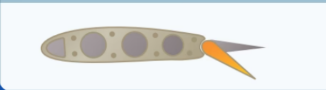
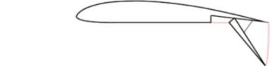
Plain Flap
a simple hinged flap that deflects downward from the trailing edge
Plain Flap
Plain Flap
Aerodynamic Effect:
Increases chamber
Moderate lift increase
High drag at larger deflections
CFD Behavior:
Early flow separation at high angles
Strong wake turbulence
Simple pressure distribution
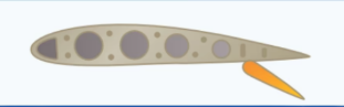
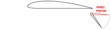
Split flap
only the lower surface deflectts downward
Split Flap
Splif Flap
Aerodynamic Effect:
High drag generation
Moderate lift increase
CFD Behavior:
Strong pressure discontinuity
Large separated flow regioon behind flap
High Turbulent wake
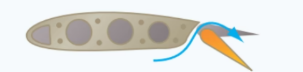
Slotted Flap
includes a slot between wing and flap
Slotted Flap
Slotted Flap
Aerodynamic Effect:
Delays flow separation
Increases lift significantly
CFD Behavior:
High-energy air from lower surface reattaches upper surface
Reduced separation zones
Improved lift-to-drag ratio compared to plain flaps
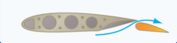
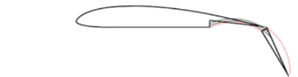
Fowler Flap
extends rearward and downward
Fowler Flap

Fowler Flap
Aerodynamic Effect:
Increases wing area AND camber
Very high lift increase
Moderate drag increase
CFD Behavior:
Larger effective lifting surface
Increased suction peak over extended chord
More complex wake but stable attached flow at moderate angles
Slotted Fowler Flap
Slotted Fowler Flap
Aerodynamic Effect:
Extremely high lift augmentation
Efficient takeoff/landing performance
CFD Behavior:
Multi-element flow interaction
Strong but controlled vortical structures
Delayed stall significantly
Gouge Flap
adjustable flap system with variable positioning
Gouge Flap
Gouge Flap
Aerodynamic Effect:
Flexible lift/drag control depending on setting
CFD Behavior:
Multiple stable operating points
Flow adapts based on flap configuration
Useful for optimization studies
Junkers Flap
mounted below trailing edge, separated from wing
Junkers Flap
Junkers Flap
Aerodynamic Effect:
Effective at high angles
Strong control authority
CFD Behavior:
Fully exposed flap generates independent airflow field
Strong vortex shedding
Reduced wing interference effects
Zap Flaps
complex multi-link mechanism increasing chord length
Zap Flaps
Zap Flaps
Aerodynamic Effect:
Very high lift coefficient
High drag when fully deployed
CFD Behavior:
Strong camber + chord extension effect
Highly nonlinear flow response
Large lift increase but complex wake
Krueger Flaps
deploys from the leading edge downward/forward
Krueger Flaps
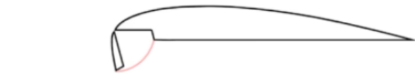
Krueger Flaps
Aerodynamic Effect:
Improves stall characteristics
Enhances low-speed lift
CFD Behavior:
Re-energizes leading-edge flow
Delays leading-edge separation bubble
Improves overall pressure recovery
Gurney Flaps
small vertical tab at trailing edge
Gurney Flaps
Gurney Flaps
Aerodynamic Effect:
Increases lift with minimal mechanical complexity
Slight drag penalty
CFD Behavior:
Generates strong trailing-edge vortex
Increases pressure difference between upper and lower surfaces
Improves circulation around airfoil
Drag
is the aerodynamic force that opposes an object’s motion as it moves through air, and it is a critical factor in aircraft performance because it directly affects fuel efficinecy, speed, and overall aerodynamic efficiency
Drag measurements
in aerodynamics, are typically obtained using wind tunnel testing or computational fluid dynamics (CFD), where the drag force is analyzed using coefficients such as the drag coefficient to compate the aerodynamic effciency of diffrent shapes and designs
Skin Friction Drag
Form Drag
Profile Drag
Interference Drag
Parasite Drag
Induced Drag
Zero-lift Drag
Wave Drag
8 Types of Drag
Induced drag
when an airfoil is flown at a positive AOA, a pressure differential exists between the upper and lower surfaces of the airfoil.
the pressure above the wing is less than atmospheric pressure and the pressure below the wing is equal of greater than atmospheric pressure
Vortex
air flows from high to low presure and tends to move outward tward the airfoil tips, causing spanwise flow from the fuselage to the tips. This results in air spilling over the tips and forming a swirling motion known as a ________
Size of lift
Aircraft speed
Aspect Ratio
3 Factors Affecting Induced Draf
Induced drag
is a component of the lift force;
the greater the lift, the greater it will be
weight
L=W in flight so, induced drag will depend on the _______ of the aircraft
Load Factor
relationship of lift to weight ratio is known as
Induced drag
decreases with increasing speed
Induced drag
decreases because as speed increases, the downwash caused by the tip vortices becomes less significant, the rearward inclination of the lift is less, and therefore induced drag is less